An end-launched rectangular waveguide adapter is used as an excitation element to transmit a modulated radio frequency (RF) signal to microwave devices such as a cavity filter and a horn antenna. The end-launched adapter consists of a rectangular waveguide and a coaxial loop shorted on the broad-wall of the waveguide. This adapter converts a coaxial mode to a waveguide dominant mode. This is known as a coaxial-to-waveguide transition and has been heavily researched. The basic theoretical procedure for the design of a coaxial-to-waveguide transition has been reported in [1-5]. However, these works could not obtain exact solutions because they applied approximation techniques to derive an expression of the input impedance.
This paper develops electromagnetic modeling of the input impedance to design an end-launched rectangular waveguide adapter by using the modal analysis method. This method gives a more accurate expression that does not use any approximation scheme for the input impedance, which is considered the dominant mode along with the higher-order modes inside a waveguide. Also, the result of the input impedance expression is analyzed and compared with the results of the previous work in [2, 4]. The validity of the proposed analytical model of input impedance is verified by an electromagnetic tool within High Frequency Structure Simulator (HFSS; ANSYS Inc, Canonsburg, PA, USA) based on a numerical method.
II. LOOP COUPLING GEOMETRY OF ENDLAUNCHED ADAPTER
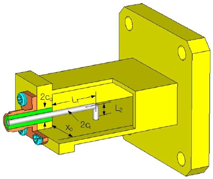
Fig. 1 shows the geometry of the end-launched rectangular waveguide adapter, where an inner conductor of the coaxial line is collinearly interconnected with the coupling loop shorted on the waveguide bottom. This type of a rectangular waveguide adapter converts the coaxial transverse electromagnetic (TEM) mode into the waveguide propagating mode. The radius of the inner conductor and the radius of the outer conductor of the coaxial line are ci and co, respectively, and the inside of the coaxial line is filled with a material with a dielectric constant of
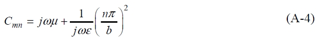
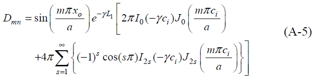
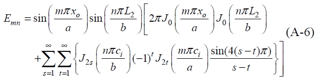
The modal analysis expression for the input impedance can be obtained as
where
The real component of the input impedance of the end-launched adapter is attributed to the dominant mode; the higher order modes only contribute to the reactive component because of evanescent modes. The shorted perpendicular arm correlates with the longitudinal arm of the loop as shown in Fig. 1, and from this, the real component of input impedance can be matched to the characteristic impedance of the coaxial line and the reactive component can be canceled out. The best performance of the end-launched adapter is achieved when the reactance cancellation occurs over the broadband operating frequency and the resistance is matched to the input impedance of the adapter connected by the coaxial line.
The input reflection coefficient and the input voltage standing wave ratio (VSWR) from (1) are defined as
where Z0 is the characteristic impedance of the input coaxial line. Re(Zin) and Im(Zin) are the real component and the imaginary component of the input impedance, respectively.
III. NUMERICAL ANALYSIS AND RESULTS
In order to analyze the adapter proposed in this paper, the physical dimensions of the rectangular waveguide are fixed on the specific waveguide WR90, but the lengths and radius of the coupling loop are controlled in order to achieve a resistance of 50 ohms through the computer simulation of (1). Therefore, the input impedance of the end-launched adapter has to be matched to the characteristic impedance of the coaxial line filled with a material with a dielectric constant of 2.1.
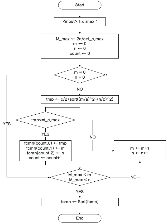
To find the behavior of the input impedance, a commercial WR90 waveguide is selected and the lengths and radius are chosen to be in the ranges of L1 = 11.4-15.4 mm, L2 = 4.0-4.4 mm, ci = 0.5-1.5 mm, and xo = 5.7-6.3 mm, respectively. According to procedure of Fig. 2 and Table 1, the number of modes is extended up to the 9th higher order mode to ensure the convergence rate of the input impedance.
From the perspective of the above physical parameters of the adapter, the input impedance of the end-launched adapter can be matched from the above physical parameters of the adapter by properly choosing the length of the loop (L1, L2), the radius of ci, and the input feeding point of xo. It is the ideal case that the resistive component of input impedance equals the characteristic impedance of the coaxial line and the reactive component equals zero to ensure the optimum design of the adapter. However, it is difficult in practice to ensure that the reactive component is zero over the whole waveguide band. Therefore, we have to have a trade-off in which the resistive component approaches the characteristic impedance of the coaxial line and also the reactive component approaches zero over the operating frequency band. This is done by controlling the physical parameters (L1, L2, ci, xo) of the coupling loop of the end-launched adapter.
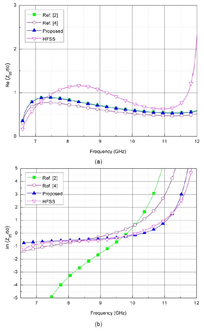
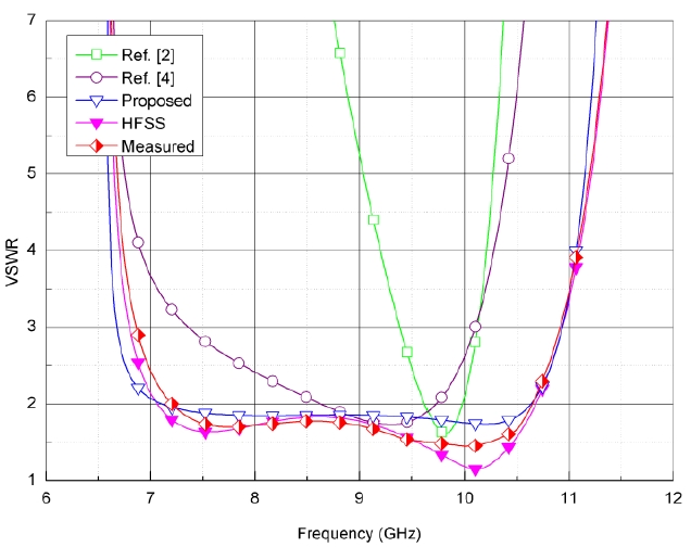
Figs. 3 and 4 show the evaluation of the input impedance and the input VSWR, respectively. The results of the proposed method, previous work, the HFSS, and the measured data have been compared with each other. The physical dimensions of the end-launched adapter have been determined to be L1 = 13.4 mm, L2 = 4.2 mm, ci = 1 mm and xo = 5.9 mm under the best-matched condition below the VSWR = 3. The comparison shows that the proposed result based on this letter for the input VSWR of the end-launched adapter agree well with the measured data and the HFSS (Δ
Fig. 5 shows the photograph of the end-fed waveguide adapter combined with the WR90 waveguide with a coupling loop. This adapter is implemented by the copper metal and coaxial feeder line with the physical parameter dimensions of Fig. 4.
[Table 1.] Higher order mode and cut-off frequency in waveguide
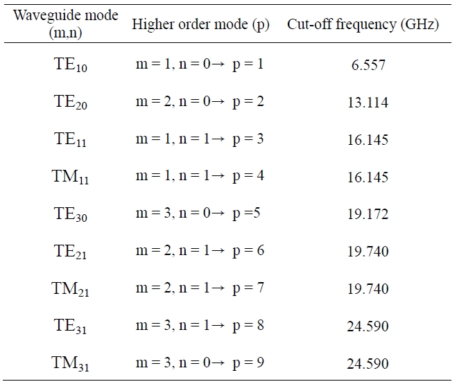
Higher order mode and cut-off frequency in waveguide
The accurate expression of the input impedance for an analysis of the end-launched rectangular waveguide adapter has been presented. It is a more accurate formula that does not use an approximation scheme considering the input impedance as the dominant mode together with the higher order modes inside a waveguide adapter. The variation of the input impedance according to the design parameters of the coupling loop has also been described. The results obtained from numerical calculation through the use of proposed method were compared with previous work, and the validity of these results is verified by a commercial electromagnetic tool in HFSS. There is a good agreement between the proposed analytical results and the results in HFSS for the input VSWR in the wideband frequency range of 7.5 GHz to 10.5 GHz. Therefore, the novel theoretical formula has more accuracy than the formulas derived in previous studies and allows the design to be based on a dependable quantitative criterion.
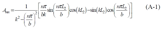
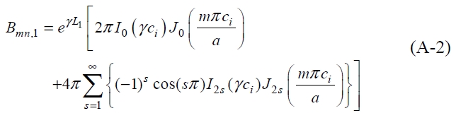
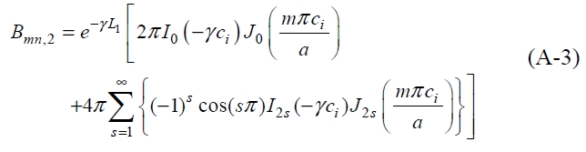
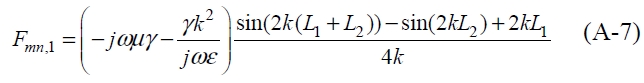
where