The oxyfluorination effects of activated carbon nanofibers (OFACFs) were investigated for CO2 storage. Electrospun CFs were prepared from a polyacrylonitrile/N,N-dimethylfor-mamide solution via electrospinning and heat treatment. The electrospun CFs were chemi-cally activated in order to generate the pore structure, and then oxyfluorination was used to modify the surface. The samples were labeled CF (electrospun CF), ACF (activated CF), OFACF-1 (O2:F2 = 7:3), OFACF-2 (O2:F2 = 5:5) and OFACF-3 (O2:F2 = 3:7). The functional group of OFACFs was investigated using X-ray photoelectron spectroscopy analysis. The C-F bonds formed on surface of ACFs. The intensities of the C-O peaks increased after oxy-fluorination and increased the oxygen content in the reaction gas. The specific surface area, pore volume and pore size of OFACFs were calculated by the Brunauer?Emmett?Teller and density functional theory equation. Through the N2 adsorption isotherm, the specific surface area and pore volume slightly decreased as a result of oxyfluorination treatment. Neverthe-less, the CO2 adsorption efficiency of oxyfluorinated ACF improved around 16 wt% due to the semi-ionic interaction effect of surface modificated oxygen functional groups and CO2 molecules.
Emissions from the combustion of fossil fuels are contributing to an increase in the con-centration of carbon dioxide (CO2) in the atmosphere. It is generally accepted that this in-crease in atmospheric CO2 may be causing global climate change. Researchers have reported that global CO2 emissions from fossil fuels increased 29% between 2000 and 2008 and 41%between 1990 and 2008. According to a new study, the current concentration of CO2 in the atmosphere is at its highest now in at past 2 million years [1]. Consequently, CO2 capture from large point sources has recently received attention as a potential means of mitigating fossil fuel CO2 emissions. Current or proposed methods for capturing CO2 from flue gas have included absorption, adsorption, cryogenic distillation, and membrane separation. However, commercial CO2 capture technology existing today is very expensive and energy intensive. Improving the technologies for CO2 adsorption is necessary in order to achieve low-energy rewards [2].
CO2 adsorption is typically used as a final polishing step in a hybrid CO2 capture system [3]. Ideally, CO2 adsorbents should have the following characteristics: a high specific surface area, well developed micro- and mesopores, and many active sites on the surfaces, such as amine functional groups and basic metal oxides [4-6]. Up to the present, different types of adsorbents have been used for CO2 adsorption, such as zeolites, alumina, mesoporous silica, CaO, and porous carbons [7-11]. In particular, porous carbons have been preferred for CO2 adsorption due to their highly de-veloped porosity, extended surface area, surface chemistry, and thermal stability. Previous studies have also used activated carbons, activated carbon fibers (ACF), carbon molecular sieves, and carbon nanotubes as adsorbents for CO2 adsorption [12-14].
In general, the adsorption capacity on porous carbon materi-als depends on the surface area and pore structures of adsor-bents. Additionally, the surface carbon/adsorbates interactions have an influence on the adsorption capacity [15-17]. Surface modification is able to change this interaction, and numerous surface modification methods have been published in the litera-ture. Of these methods, fluorination is one of the most effective methods for modifing carbon surfaces [18-21]. Because fluorine gas has a strong reactivity, it can easily react with surface ca-rbon, even at room temperature. Furthermore, the surface nature of activated carbons can be controlled, regardless of whether they are hydrophobic or hydrophilic, by direct fluorination and oxyfluorination [22].
We modified activated electrospun CFs with fluorine gas, and characterized the changes in its surface properties and pore structure before and after oxyfluorination. Afterwards, we investigated the interaction of adsorbent?adsorbate from CO2 adsorption isotherms of oxyfluorinated activated elec-trospun CFs at 273 K. From these results, we determined the relationship between the storage capacity and the pore struc-tures of the ACF samples. This paper reports our preliminary results on the catalytic effect of ACFs modified by F2 and its potential benefits.
Polyacrylonitrile (PAN, d = 1.184, Aldrich) was used as a car-bon source. N,N-dimethyl formamide (DMF) was adopted as a solvent, because its boiling point is 426 K and it has a conductiv-ity (conductivity = 10.90
The KOH solutions (6 M) were prepared as chemical acti-vation agents. The CF sample was placed on an alumina boat at a ratio of 10 mL/g (KOH solution/CF) in a steel pipe to carry out the chemical activation. Activation was conducted at 1023 K for 3 h in an argon atmosphere. The heating rate was 5 K/min, and the feed rate of the argon gas was 40 mL/min. After chemical activation, samples were washed with distilled water several times to remove residual potassium. These were then dried at 383 K overnight. These activated carbon nanofibers are called ACF.
2.2. Surface modification by oxyfluorination of ACFs
As a pretreatment step, ACFs were heated at 70℃ for 24 h to remove impurities. The oxyfluorination was carried out at 1 bar for 5 min with oxygen: fluorine gas ratios of 7:3, 5:5 and 3:7. These oxyfluorinated samples are labeled oxyfluorination effects of activated carbon nanofiber (OFACF)-1 (O2:F2 = 7:3), OFACF-2 (O2:F2 = 5:5) and OFACF-3 (O2:F2 = 3:7). More de-tails on this reaction are provided in a previous study [26].
2.3. Characterization of prepared samples
The X-ray photoelectron spectroscopy (XPS) spectra of the samples were obtained using a MultiLab 2000 spectrometer (Thermo Electron Corporation, England) in order to investigate the elements present in the samples. Al Ka (1485.6 eV) was used as the X-ray source with a 14.9-keV anode voltage, a 4.6-A fila-ment current and a 20-mA emission current. All samples were treated at 10-9 mbar to remove impurities. The survey spectra were obtained at a 50-eV pass energy and a 0.5-eV step size.
The textural properties of the all the samples were investi-gated. Samples were degassed at 423 K for 3 h, and then, ni-trogen adsorption was carried out at 77 K using a Brunauer?Emmett?Teller (BET) apparatus (Micromeritics ASAP 2020) to investigate the specific surface area, total pore volume, pore size distribution and micropore fraction.
The CO2 adsorption capacity was measured by CO2 isother-mal adsorption at 273 K and 1 atm. Furthermore, the parameters of the Dubinin?Astakhov equation:
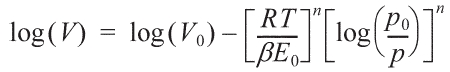
were obtained from CO2 adsorption.
3.1. Surface properties of oxyfluorinated ACFs
XPS analysis was very useful for characterizing the surface chemical structures of the oxyfluorinated ACFs in the previous
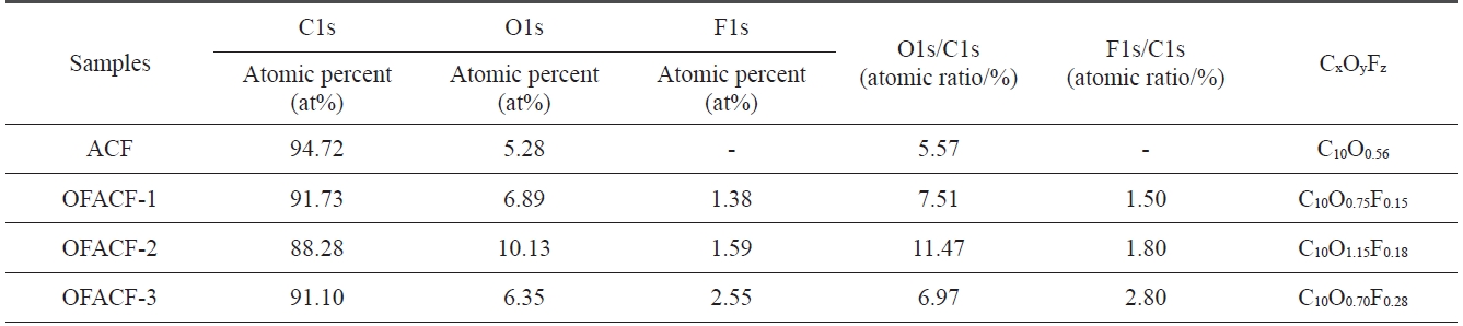
[Table 1.] XPS surface element analysis of as-received and OFACFs

XPS surface element analysis of as-received and OFACFs
studies [27-29]. Characterization of the surface chemical com-position of the oxyfluorinated ACFs was carried out using XPS analysis. Table 1 lists the atomic ratio of each element on the surface of the ACFs. The surface carbon concentration of the samples decreased dramatically after oxyfluorination, whereas the fluorine atomic ratio of the samples significantly increased. In addition, the O1s peaks of the oxyfluorinated ACFs slightly increased with the decrease in fluorine partial pressure, but the O1s peak of sample OFACF-3 decreased because there was in-sufficient fluorine gas to react with the oxygen gas.
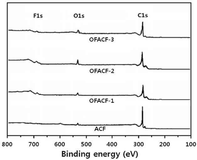
Fig. 1 shows the elemental survey of pristine and oxyfluori-nated ACFs. In the ACF sample, C1s and O1s peaks represent the carbon atoms from ACFs and the oxygen atoms from the H2O adsorption on ACFs from the ambient atmosphere, respective-ly. The peaks of O1s and F1s confirmed the introduction of both oxygen and fluorine atoms, respectively, on the oxyfluorinated ACFs. The peak intensities varied depending on the composi-tion of the reactive gases. In the C1s spectra of oxyfluorinated ACFs, the peak intensity increased with decreasing fluorination pressure. Fluorine gas appeared to react with the carbon more actively than with the oxygen, resulting in the breakage of the sp2 carbon aromatic structure. The carbon-oxygen single and double-bond peak intensities increased with increasing oxygen content in the reactive gas [30]. In sample OFACF-2, the total content of carbon-oxygen single and double bonds increased by over 20%. These carbon?oxygen bonds contributed to the increased hydrophilicity of the ACFs; while in the OFACF-3 sample, the total content of carbon-oxygen single- and double-bonds decreased because there was insufficient fluorine gas to react with the oxygen gas. The fluorinated carbon bonds were observed as semi-ionic and covalent carbon-fluorine bonds [31]. Even though the intensities of all of the fluorinated carbon bonds increased as the fluorine content in the reactive gas increased, the covalent carbon-fluorine bond was dominant.
The O1s and F1s peaks were also investigated as supplementary data for interpreting the C1s peaks. The variation in the O1s peaks corresponded well with the variation of the C1s peaks upon oxy-fluorination. The carbon-oxygen single and double bonds were produced more favorably by oxyfluorination. The variation in the F1s peaks also corresponded well with the variation of the C1s peaks upon oxyfluorination. The covalent carbon-fluorine bonds were more dominant when the fluorine content in the reactive gas was increased.
The changes in the chemical bonds of the ACFs after oxyfluo-rination were investigated by C1s deconvolution, and the results are depicted in Fig. 2. Table 2 lists the C1s spectra and assignments of the oxyfluorinated ACFs. The C1s peaks of oxyfluorinated ACFs was deconvoluted to several pseudo-Voigt functions (sums of the Gaussian and Lorentzian functions) using a peak-analysis program obtained from Unipress Co., USA. The pseudo-Voigt function is given by [32]:
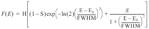
where F(E) is the intensity at energy E, H is the peak height, E0 is the peak center and S is a shape function related to the symmetry and the Gaussian?Lorentzian mixing ratio. The components ob-served for ACF were C(1), C(2), C(3), and C(4) at 284.5, 285.7, 86.9, and 288.1 eV, corresponding respectively to the sp2 car-bon, sp3 carbon, carbon-oxygen single- and double-bonds. After oxyfluorination, the C(5) and C(6) components were observed in OFACF-1, OFACF-2, and OFACF-3 samples at 289.3 and 290.5 eV, corresponding to semi-covalent and covalent carbon-fluo-rine, respectively. All of these results are in accord with those from other studies [19,21,27-29,33-35]. The concentration of C(3) and C(4) increased as the O2 to F2 ratio increased in the gas mixture, whereas the ratio only decreased in the OFACF-3 sample because there was insufficient fluorine gas to react with
[Table 2.] C1s spectra and assignment of the OFACFs
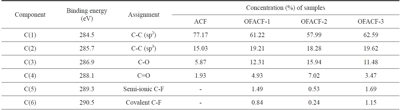
C1s spectra and assignment of the OFACFs
the oxygen gas, as previously mentioned. However, C(5) and C(6) decreased with a decreasing F2 ratio in the gas. The effect of the functional groups discussed in this section will be further discussed in later sections.
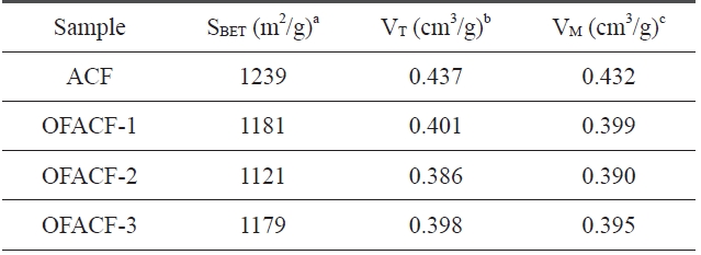
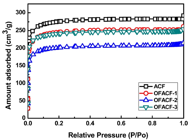
A summary of the textural properties is presented in Table .3 KOH activation has the effect of increas-ing specific surfacearea, total pore volume, and micropore volume while increasing the concentration of the used chemical agent solution. The nitrogen isotherms of the samples are shown in Fig. 3. All of the curves have an inflection point, which is called a ‘knee,’ around P/P0 (0.01). This point indicates that monolayer adsorption is complete. Thus, it is possible to calculate the specific surface area at this point using the BET equation. Generally, in the low-pressure region, less than around 0.1 P/P0, the steep curve of the isotherm indicates the development of the micropore struc-
[Table 3.] Textural properties of the un-oxyfluorinated and OFACFs

Textural properties of the un-oxyfluorinated and OFACFs
ture, and the change in the relatively high-pressure region indi-cates the improvement of meso/macro pores [36]. In the case of OFACF-1, OFACF-2 and OFACF-3, a well-developed mi-croporous property was confirmed by the striking initial change in the low relative pressure range [37]. In our previous work, it was shown that KOH activated carbon nanofibers have highly
developed micropores, and oxyfluorination treatment of ACFs does not significantly affect the pore structure under the condi-tions used [26].
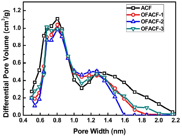
The pore size distribution was evaluated by applying a non-local density functional theory (NLDFT) model, as shown in Fig. 4. The NLDFT model was applied under the assumption that the slit-shaped pores have uniformly dense carbon walls and that the adso-rbate is a fluid of hard spheres [38]. Additionally, the interaction between adsorbent and adsorbate was considered on their elemental spe-cies by a soft program installed on the BET apparatus. The pore width was distributed mainly in the micopore range, especially in the range of 0.7-1.6 nm. Based on the infor-mation provided by other groups, this pore size distribu-tion would be very beneficial for CO2 uptake, because it has been predicted that the optimized pore size for enhanc-ing the capacity of CO2 storage in carbon materials is 0.8-1.1 nm [39,40].
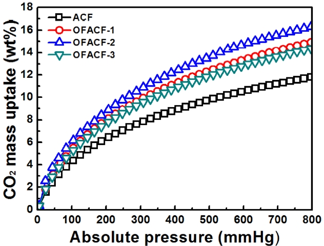
Adsorption equilibrium isotherms of CO2 on all samples at 273 K are plotted in Fig. 5. It can be seen that the OFACFs had a better performance in CO2 adsorption than the pris-tine ACFs. This may occur because the filling of micropores with CO2 gas is increase at that pressure [41]. This clearly indicates that modification by KOH activation and oxyfluo-rination treatment increase the affinity of ACFs toward CO2. Comparing ACFs, a higher CO2 uptake can be observed in the case of OFACF-2. The cause is surely the more highly-developed pore structure. Based on the investigation of oxyfluorination effects for enhancing CO2 storage, the CO2 uptake of the oxyfluorinated samples was studied. In all pres-sure ranges, oxyfluorination effects can be observed, showing a higher capacity of CO2uptake than raw ACF. It is around 11% (OFACF-1 and OFACF-3) and 30% (OFACF-2) higher, as compared with ACF sample, respectively. Overall, the CO2 uptakes of the samples were 11.2 (ACF), 14.2 (OFACF-1), 16.2 (OFACF-2) and 13.9 wt% (OFACF-3).
3.4. Suggested mechanism for the improved effects of oxyfluorinated ACFs
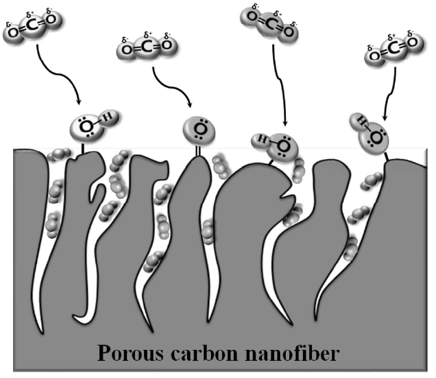
The mechanism of CO2 storage in the slit pores of oxyfluorinated ACFs is suggested in Fig. 6. The CO2 molecule has a non-polar structure. The CO2 molecules near the carbon pores are affected by the semi-ionic interaction of oxygen groups, which has the lone-pair electron, causing the attraction of the electrons in the CO2 mol-ecules,as shown in Fig. 6. This reaction might play an important role as a guide for enhancing the CO2 storage capacity. Eventually, the CO2 gas can be stored in the slit pores of carbon. Some of the residual CO2 molecules in the carbon silt pores can be also affected by oxygen group effects, such as the grabbing effects due to semi ionic interaction, resulting in the high efficiency of CO2 storage. All of these reactions were carried out without any chemical bonds between the CO2 molecules and the carbon pores, so the desorption of CO2 is easily reversible for ease of use.
In conclusion, we have shown that the CO2 adsorption be-haviors of ACFs are directly related to oxyfluorination. Samples were oxyfluorinated for surface modification to investigate the semi-ionic interaction effect of enhancing the capacity of CO2 storage by oxygen group. The resulting samples were highly microporous, over 85%, with a high specific surface area greater than 1200 m2/g and a pore size distribution in the range of 0.7-1.6 nm, optimal for CO2 storage. Eventually, the CO2 uptake increased up to 16.2 wt% due to the highly developed micropore structure and semi-ionic interaction effect of oxyfluorination.