Multilayered silicates have been introduced to polymer matrices on the nano scale to give them certain special characteristics such as electrical insulating capacity, modulus, hardness,and thermal stability. The best-known of the materials used are montmorillonite, saponite, hectorite, talc, and mica [1-3]. They are generally introduced to a polymer matrix in a bulk shape of micro-size, and they should be separated into sheet-like monolayers to act as nano particles in a polymer matrix of dimension(20-1,000) × (20-1,000) × 1 nm3. The driving force separating the sheets from each other is provided by the penetration characteristics of polymer chains moving through the galleries between the silicate monolayers, resulting in intercalated or exfoliated nanocomposites [1,2]. However, it is very difficult for the hydrophobic polymer chains to penetrate into the galleries because their atmosphere is hydrophilic. Therefore, the atmosphere of the galleries needs to be modified by organophilic alkyl ammonium cations using the cation exchange process[4-6].
Epoxy resin is a good material for the insulation systems in heavy electric equipment because it has good mechanical and thermal properties as well as excellent electrical properties [7-9].Therefore, new epoxy-based composites which combine higher performance with lower cost have been developed for electrical applications. It has been found that 65-80 wt% loading of microsilica improves the dimensional stability, mechanical, and thermal properties of the pure epoxy systems, contributing to the dimensional stability of the heavy electric equipment which is generally operated at 40°C-60°C. Furthermore, a new concept of a mixture of nano- and micro-fillers for epoxy-based composites was proposed by Imai et al. [10-12], where the mixture systems were composed of micro-silica and nano-silica or multilayered silicate.
In this study, epoxy/layered silicate nanocomposites have
[Table 1.] Characteristics of layered silicates.
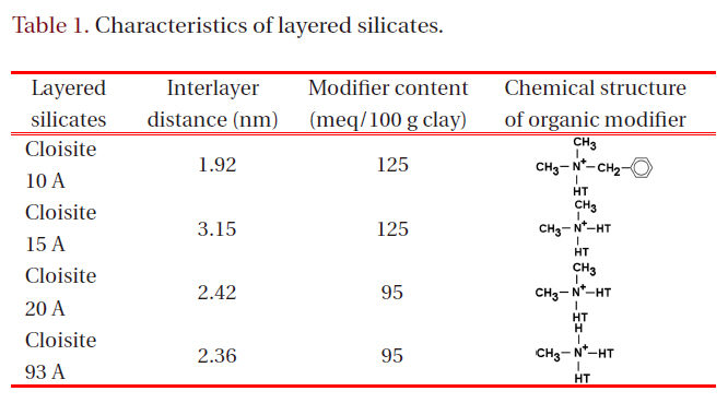
Characteristics of layered silicates.
been developed by incorporating four different kinds of organically modified layered silicate into an epoxy matrix, which will be used to synthesize epoxy/nano- and micro-filler mixture composites in future research by the authors. The thermal, mechanical and electrical properties of these composites were also studied.
All the layered silicates used were purchased from Southern Clay Products Inc. (Gonzales, TX, USA), under trade names Cloisite® 10 A, 15 A, 20 A, and 93 A. These materials are natural montmorillonite minerals modified with various organic modifiers. The interlayer distances, cation exchange capacities(meq/100 g clay), and chemical structures of the organic modifiers are shown in Table 1, where HT is hydrogenated tallow (~65%C18; ~30% C16; ~5% C14) and the anion is chloride. The layered silicates were dried at 100°C for 10 hours in a vacuum oven and stored in a desiccator.
A commercial diglycidyl ether of bisphenol A (DGEBA)-type epoxy resin with trade name YD 128 (Kukdo Chem. Co., Seoul,Korea) was used. The epoxy equivalent weight was 184-190 g/eq,and the viscosity was 11,500-13,500 cps at 25°C. The curing agent was 3- or 4-methyl-1,2,3,6-tetrahydrophthalic anhydride (Me-THPA) with grade name HN-2200 (Hitachi Chem. Co., Tokyo,Japan). This compound is widely used in the field of electrical insulation. The tertiary amine-type accelerator used was benzyldimethyl amine (BDMA; Kukdo Chem. Co., Kukdo, Korea).
2.2 Preparation of nanocomposite
Epoxy base resin (DGEBA, 100 g) and each layered silicate (5 g) were well mixed using a planetary centrifugal mixer (ARE-250,Thinky Corporation, Made in Japan) at 2,000 rpm for 20 minutes.Then Me-THPA (80 g) and BDMA (0.9 g) were sequentially poured into the epoxy/layered silicate mixture using a mechanical stirrer for 10 minutes. The mixture was then degassed using a planetary centrifugal mixer at 2,000 rpm for 8 minutes. Then it was cured at 150°C for 2 hours in a vacuum oven.
The changes of interlayer distance were measured using a wide-angle X-ray scattering diffractometer (WAXD, XRD30;Rigaku, MD,USA). The X-ray beam consisted of nickel-filtered Cu K1 (λ = 0.154 nm) radiation operated at a tube voltage of 40 kV and a tube current of 30 mA. The scanning range was 2θ = 1.0°-10°at a rate of 1°/min.
The morphology of the layered silicate in the epoxy matrix was
observed using a high-resolution transmission electron microscope(TEM, Hitachi S-4100; agency Korea, Seoul, Korea). The nanocomposite was cut into ultrathin sections of approximately 70-90 nm using a Power TOME X microtome equipped with a diamond knife, and the ultrathin sections were placed on a 200-mesh copper grid. The measurement was performed using an accelerating voltage of 200 kV
Dynamic differential scanning calorimetry (DSC) analysis was performed as follows: approximately 2-3 mg of cured sample was weighed exactly into an aluminum pan and was then loaded into a DSC furnace (Instrument Specialists Incorporated, DSC Infinity Series, TA Instrument Ltd, USA). Then DSC analysis was performed at a heating rate of 10°C/min in a nitrogen atmosphere at 40 ml/min.
A flexural test was carried out using a universal testing machine(SHM-C-500, Shamhan Tech, Seoul,Korea). The specimen was prepared according to the recommendations of JIS B7502 and tested at a crosshead speed of 10 mm/min at 23°C and 50%relative humidity.
2.4 Nanocomposites insulation breakdown
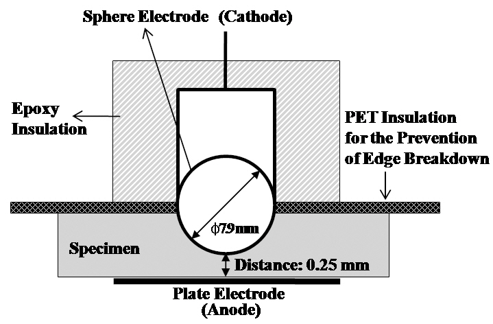
Sphere-plate electrodes were arranged to measure the nanocomposites(AC) insulation breakdown strength, as shown in Fig. 1. The cast specimen was designed to be 0.25 mm thick at its thinnest point, and it was positioned between the electrodes in the expectation that the insulation breakdown would take place in that point. However, edge breakdown took place in many cases, so the upper half of the sphere electrode was insulated by epoxy resin and PET film to prevent edge discharge and breakdown.The electrodes and specimen were dipped into insulating oil at 30°C, and a high voltage was applied until electrical breakdown,increasing at a rate of 2 kV/s.
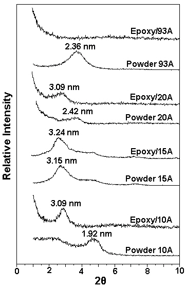
To calculate the interlayer distance of the layered silicate powders and cured epoxy nanocomposites, WAXD analysis was carried out, and the resulting patterns are shown in Fig. 2. The number above the peak of each pattern in nm is the interlayer distance as calculated by Bragg’s formula [13], λ = 2d sinθ, whereλ is the wavelength of the X-ray beam (λ = 0.154 nm), d the dspace,and θ the scattering angle. For example, the peak at 2θ =4.59° shown on the pattern for powder 10A means that the interlayer distance (d-space) for powder 10 A is 1.92 nm. As powder 10 A was dispersed and cured in the epoxy matrix, the peak for the d-space was shifted to a lower peak at 2θ = 2.85° (d-space =3.09 nm), with the result that the d-space of powder 10A became
1.17 nm wider due to the intercalation of the epoxy resin.
In the cases of epoxy/15 A and epoxy/20 A, there was no difference in the d-space, but nevertheless there was a large difference in d-space between powders 15 A and 20 A. There was only a difference in the modifier content, as shown in Table 1. The d-space of powder 15 A with 125 meq/100 clay of modifier content was 0.73 nm wider than that of powder 20 A with 95 meq/100 clay.However, the effect of the organic modifier on the intercalation of the epoxy resin was very small.
On the other hand, the effect of the organic modifier in powder 93 A was very pronounced, as shown in the WAXD pattern of epoxy/93 A in Fig. 2. The peak for powder 93 A has disappeared,
which means that the d-space of powder 93 A is far wider than those of other systems.
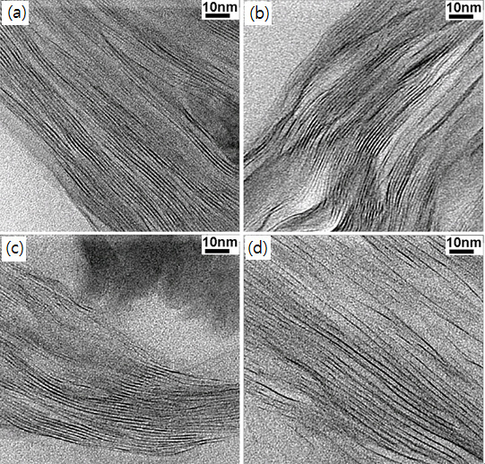
The intercalation state was confirmed by TEM observation, as shown in Figs. 3(a)-(c) represent the cured epoxy/10 A, epoxy/15 A and epoxy/20 A systems respectively, where the silicate layers were displayed as dark lines with an ordered arrangement.The d-space values between the dark lines are approximately 3 nm in the three images, which agrees well with the results of the WAXD analysis. In Fig. 3(d), the d-space becomes approximately two times wider than those shown in Figs. 3(a)-(c). However, the order of arrangement was almost maintained, except for a little exfoliation in the right-center area of Fig. 3(d). These results also agree well with the result of WAXD analysis.
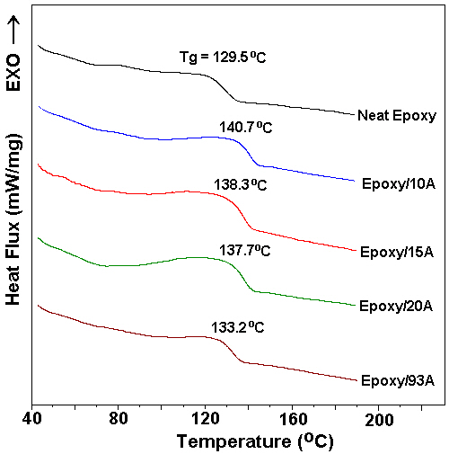
To obtain the glass transition temperature, Tg, a DSC analysis was carried out at 10°C/min, and Tg was measured from the DSC curves, as shown in Fig. 4. The Tg value was increased by addition of layered silicates, regardless of the kind of modifier,
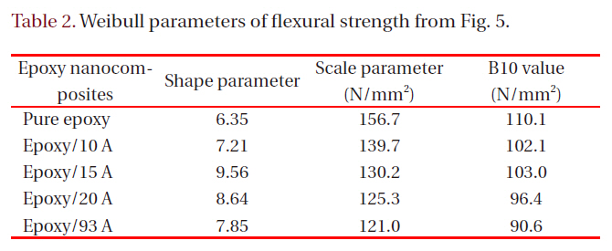
[Table 2.] Weibull parameters of flexural strength from Fig. 5.

Weibull parameters of flexural strength from Fig. 5.
because of hydrogen bonding between hydroxyl groups in the epoxy matrix and a silanol group on the silicate surface. When the silicate layers became intercalated into nanoscale layers,their surface area became larger, and therefore the number of hydrogen bonding sites increased. However, a larger number of nanoscale layers may interrupted the curing reaction between the epoxy resin and the curing agent, resulting in a low Tg value for epoxy/93 A.
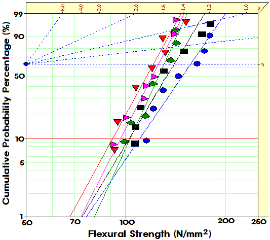
Figure 5 shows Weibull plots of flexural strength for pure epoxy resin and epoxy nanocomposites with various modifiers; the parameters are listed in Table 2. Statistical analysis showed that the flexural strength of the pure epoxy was 156.7 N/mm2 and that the strength values for the various nanocomposites were greater than that of pure epoxy.
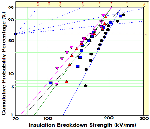
Figure 6 showed Weibull plots of AC insulation breakdown strength for pure epoxy resin and epoxy nanocomposites; their Weibull distribution parameters are listed in Table 3. The shape parameter can be obtained from the slope of the data distribution,and the scale parameter represented the flexural strength by which 63.2% of the cumulative samples could be expected to fail. B10 refers to the flexural strength at which 10% of the samples would fail (90% would survive) under a given stress. Statistical analysis showed that the AC insulation breakdown strength was 161.2 kV/mm for the pure epoxy resin, but that the values for the epoxy nanocomposites were remarkably improved. In the case of the shape parameter, the value for pure epoxy resin was 5.88, and the values for the epoxy nanocomposites were slightly increased by addition of intercalated silicate. The higher the gradient became, the more homogeneous were the breakdown strength data. These results mean that the intercalated plate
[Table 3.] Weibull parameters of AC insulation breakdown strength in Fig. 6.
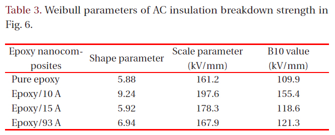
Weibull parameters of AC insulation breakdown strength in Fig. 6.
plateshaped nano-size silicates were evenly dispersed in the epoxy matrix and imparted improved AC insulation breakdown characteristics to the epoxy resin. The best parameters were shown in epoxy/10 A nanocomposite.
New electrical insulating materials for heavy electric equipment were prepared by mixing an epoxy matrix and various kinds of nano-sized layered silicates, where each nano-sized silicate was prepared from each multilayered silicate using a planetary centrifugal mixer. The WAXD peak at 2θ = 3.67° (d-space= 2.40 nm) for Cloisite® 93 A disappeared in the cured nanocomposite system. However, each peak for the d-space of other layered silicates was shifted to a lower scattering angle, but did not disappear in the cured nanocomposite systems. The TEM observations agreed well with the WAXD results. Weibull statistical analysis showed that the flexural strength of the pure epoxy was 156.7 N/mm2 and that the values for nanocomposites with various layered silicates were lower than that of the pure epoxy.Weibull statistical analysis for AC insulation breakdown strength yielded 161.2 kV/mm in the pure epoxy resin, and the values for the epoxy nanocomposites were remarkably improved by the addition of intercalated silicates. The best insulation properties were estimated for the epoxy/10 A nanocomposite.

![Wide-angle X-ray scattering diffractometer patterns for layeredsilicate powders and cured epoxy nanocomposites. The numberabove the peak of each pattern in nm is the interlayer distance ascalculated by Bragg’s formula [13].](http://oak.go.kr/repository/journal/10900/E1TEAO_2011_v12n4_135_f002.jpg)