The computer industry is rapidly moving toward single-chip multi-core processors or chip multiprocessors (CMP) with the scaling of technology and the diminishing returns of complex uniprocessors. Multi-core processors have been widely used in servers, desktops, and embedded systems. In particular, with the growing demand of high performance for high-end real-time applications, such as high-definition television (HDTV) and video encoding/decoding standards, it is expected that multi-core processors will be increasingly used in real-time systems to achieve higher performance/throughput cost-effectively. It is projected that real-time applications will be likely deployed on large-scale multi-core platforms with tens or even hundreds of cores per chip fairly soon [1].
It is crucial to obtain the worst-case execution time (WCET) of each real-time task, for real-time systems, especially hard real-time systems. This will provide the basis for schedulability analysis. Missing deadlines in those systems may lead to serious consequences; this is not allowed. While the WCET of a single task can be measured for a given input, it is generally infeasible to exhaust all the possible program paths through measurement. Another approach to obtaining WCET is to use static WCET analysis (simply termed WCET analysis). WCET analysis typically consists of three phases: program flow analysis, low-level analysis, and WCET calculation. While the program flow analysis analyzes the control flow of the assembly programs that are machine-independent, the low-level analysis analyzes the timing behavior of the microarchitectural components. The WCET calculation phase computes the estimated worst-case execution cycles using methods, such as path-based approach [2, 3] or implicit path enumeration technique (IPET) [4-6], based on the information obtained from the program flow analysis and the low-level analysis.
While there have been many research efforts on WCET analysis for single-core processors [1-6], to our best knowledge only a few recent efforts [7-9] study how to bind the WCET for multi-core processors with shared L2 instruction caches. A major reason is probably the significant complexity involved with the WCET analysis for multi-core processors. Even for today’s single-core processors, many architectural features, such as cache memories, pipelines, out-of-order execution, speculation and branch prediction have made “accurate timing analysis very hard to obtain” [10]. Multi-core computing platforms can further aggravate the complexity of WCET analysis due to the possible inter-thread interference in shared resources, such as L2 caches, which are very difficult to analyze statically. While there have been some recent research efforts on real-time scheduling for multi-core platforms [1, 11, 12], all these studies assume the worst-case performance of real-time threads is known. Therefore, it is necessary to reasonably bind the WCET of real-time threads running on multi-core processors before multi-core platforms can be safely employed by real-time systems.
This paper presents a novel approach to analyze the maximum interferences and bounding the worst-case performance for threads running on multi-core processors with shared L2 instruction caches. The idea of our approach is to detect the maximum L2 access interference, by exploiting the L2 access sequence for different threads that can be acquired by examining edge transition from the calculation of integer linear programming (ILP). This also differentiates this from our previous work [7] that is based on the analysis of the appearance of L2 accesses for multi-core processor WCET calculation. Also, compared to related work in [8, 9], in which the computation cost is high, the algorithms proposed in this paper are very efficient. Most benchmarks studied in this paper can be analyzed within seconds.
The remainder of the paper is organized as follows. First, we discuss the paradigm of the WCET analysis for multi-core chips with shared caches in Section II. Then we describe our approach to computing the worst-case shared L2 instruction cache performance and the WCET for multi-core processors in Section III. The evaluation methodology is given in Section IV. Experimental results are presented in Section V. We discuss related work in Section VI. We make concluding remarks in Section VII.
II. PARADIGM OF WCET ANALYSIS FOR MULTICORE CHIPS WITH SHARED L2 CACHES
In a multi-core processor, each core typically has private L1 instruction and data caches. The L2 (and/or L3) caches can be either shared or private. While private L2 caches are more time-predictable in the sense that there are no inter-core conflicts, each core can only exploit limited cache space. Due to the great impact of the L2 cache hit rate on the performance of multi-core processors [13, 14], private L2 caches may have worse performance than shared L2 caches with the same total
size, because each core with the shared L2 cache can make use of the aggregate L2 cache space more effectively. Moreover, shared L2 cache architecture makes it easier for multiple cooperative threads to share instructions, data, and the precious memory bandwidth to maximize performance. Therefore, in this paper, we focus on WCET analysis of multi-core processors with shared L2 caches (by contrast, the WCET analysis for multi-core chips with private L2 caches is a less challenging problem).
>
A. A Dual-Core Processor with a Shared L2 Cache
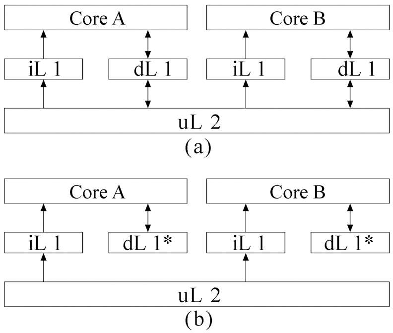
A typical dual-core processor, as can be seen in Fig. 1a, has private L1 instruction caches, private L1 data caches, and a unified L2 cache. Since this paper focuses on the inter-thread interference for instruction caches, we slightly modify the processor in Fig. 1a, as in Fig. 1b. We still assume a dual-core processor with two levels of cache memory. However, as can be seen from Fig. 1, in this dual-core processor, each core has its own L1 instruction cache and perfect data cache (dL1*). Only L1 instruction caches share a unified L2 instruction cache. Meanwhile, we apply our proposed approach to instruction caches that can be easily extended to data caches. We assume that a real-time thread (RT) and a none real-time thread (NRT) are running simultaneously on these two cores. Our goal is to detect the maximum interference for the RT by considering the NRT and give a tight bound on WCET for RT.
>
B. Conflicts between Real-time Thread and None Real-time Thread
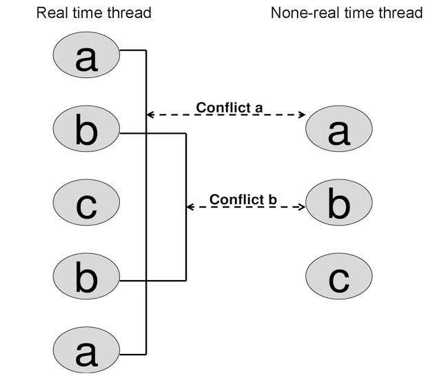
First, we present how a conflict arises. In a single-core processor, L2 reference may be pre-fetched before its access occurs due to the inclusion of L1 caches. This leads to a L2 hit when a reference tries to access the pre-fetched L2 reference. A loop body is another scenario for a L2 hit, if no two or more L2 references are mapped to the same cache line, then the remaining accesses of this L2 cache line should be always hit, except for a cold miss. However, in a multi-core processor, shared L2 cache may introduce conflicts between the Real-time thread and none
real-time thread, when they run simultaneously. This makes the above-mentioned L2 hit scenarios never hold under the worstcase circumstance.
Let us see the example in Fig. 2 in which two threads run and access the unified L2 cache. The access sequence for the real time thread is {a b c b a}. The sequence for the none realtime thread is {a b c}. Here, letters
Without considering the conflicts between real time thread and none real-time thread, the first three references of the real time thread {a b c} are misses and the remaining references {b a} are hits.1 Now, if we take the none real-time thread into account, we notice that none real-time thread uses the same cache lines as in the real time thread. Specifically, the none real-time thread also accesses {a b c}. Therefore, a situation may exist when, after the first reference of the real time thread, the first reference of the none real-time thread occurs. Then, the reference from the none real-time thread evicts the reference of the real time thread out of the cache line. Consequently, it turns the next access to this cache line from a real time thread into a miss. In Fig. 2, two conflicts, labeled
>
C. Detecting the Maximum Interferences in Shared L2 Cache
The most difficult problem for multi-core WCET analysis is to find the maximum interference in shared L2 cache. As above mentioned in section 2.2, the inter-core L2 instruction interference depends on several factors, including 1) the instruction addresses of the L2 accesses of each thread, 2) which cache block these instructions may be mapped to, 3)
1. In order intra-thread access. Accesses to L2 shared cache for both real time thread and none real-time thread are in order. The order of references cannot be altered.
2. Maximum one impact or none. For a none real-time thread,each reference is only able to produce one miss impact on real time thread or NONE. Although, it may actually conflict with multi-accesses in the real-time thread.
3. No impact on miss. If a reference of a real time thread is a miss, then no impact will be considered.
4. Impact on hit. If a reference of a real time thread is a hit, then it may be affected by a none real-time thread. When a hit is affected by the none real-time thread reference, a miss is produced.
Rule 1 specifies the L2 access sequences for both real time thread and none real-time thread. This serves as the basis for static timing analysis. The sequences can be acquired by analyzing the edge transition information from ILP [4]. Rule 2 defines the maximum interferences from each none real-time thread access to the real-time thread reference. This gives the upper bound for maximum interferences that could be produced by considering the none real-time thread. Rules 3 and 4 are straightforward. We propose to formulate our problem using a matrix, based on the above-mentioned assumptions/observations, as follows.
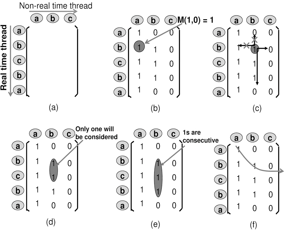
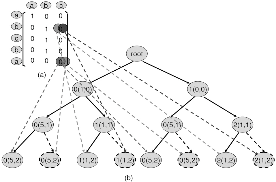
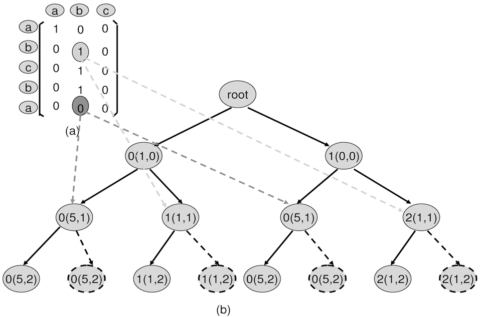
1. Matrix definition. Starting from the left-top, the top-todown axis is the reference from the real time thread, and the left-to-right axis is the references from the none realtime thread. E.g. in Fig. 3a, the real-time thread access sequence is placed in row order, and none real-time thread access sequence is placed in column order.
2. Matrix construction. For each element Mij in matrix, i is the row position and j is the column position. Mij =1, when the jth reference from the none real-time thread is inserted
into the ith position of the real time thread access sequence. It impacts the real time thread. Otherwise, Mij=0. E.g. in Fig. 3b, M10=1, because it evicts the real-time cache reference (a) out of L2 cache, when placing 0th access (a) from none real-time thread to 1th position of real-time access sequence. This leads the 4th access (a) of the real-time thread to miss. This is an impact by our definition.
3. Matrix iteration. Starting at any point, it can only walk right-to-left and top-to-down. E.g. in Fig. 3c, at position (1,1), the next available positions are (1,2) or (2,1).
4. Down iteration wall. Starting at any point, when walking down, only one 1 will be considered. This is from the observation of item 2. E.g. in Fig. 3d, although reference (b) from the none real-time thread can impact the real-time thread from position (1,1) through (3,1), only one position of (1,1) through (3,1) should be considered as valid 1.
5. Consecutive 1s. For any column, the impact from the none real-time thread to the real time thread is consecutive. Starting from the first position (i,k) through (j,k), all Mi...j,k=1.E.g. in Fig. 3e, reference (b) starts to impact the real-time thread from position (1,1) through (3,1), thus all M1...3,1 are 1.
6. Longest path. The path with the maximum number of 1s will be the longest path. E.g. as can be seen in Fig. 3f, one of the possible longest paths is (0,0), (1,1) and (1,2).
The problem to detect the maximum interference for the multi-core processor with shared L2 instruction cache can now be defined as how to determine the
1Suppose the cache is sufficiently large in this example.
Observation 2 tells us that each none real-time thread access produces either a 1 (impact) on the real-time thread or 0 (no impact) on the real-time thread. Therefore, at any column of the matrix, only two statuses could be encountered. Motivated by this observation, we propose to use a binary tree search to determine the
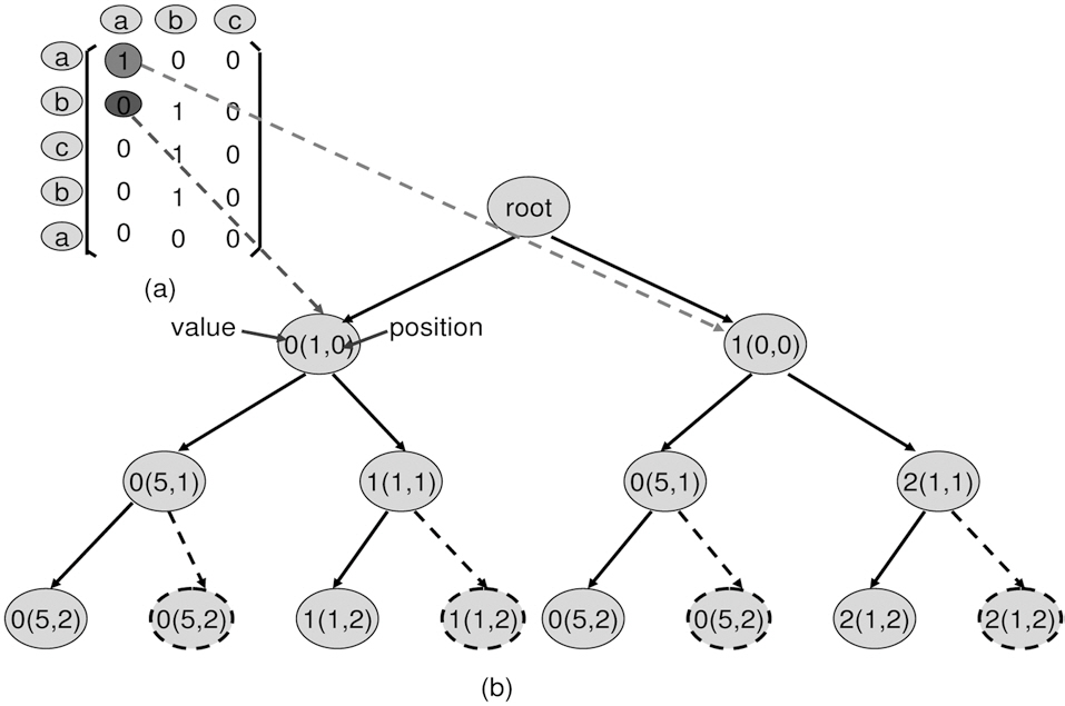
Suppose the matrix is an m×n matrix, each column produces only two statuses, impact on the real time thread, and no impact on the real time thread. Thus, from left-to-right we can build a binary tree with one leaf representing the impact on the real time thread and another leaf representing no impact on the real time thread. After tree construction, from any leave to the root, the path with the maximum number of “1”s is the longest path. In our implementation, we use the right leaf to represent the impact on the real time thread, and the left leaf to represent no impact on the real time thread.
1) Searching Algorithm:
This algorithm has three arguments, as shown at line 2 to line 4. Argument
Two auxiliary functions
In this algorithm, the convergence condition is line 7. That is, end-leaves are encountered, when the program reaches the last column of the matrix.
It should be noted that it is too expensive to exhaust all the paths. Therefore, there are also three pruned-leaf conditions in our algorithm. They can significantly reduce the time complexity, as follows.
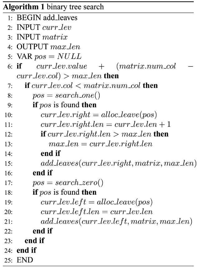
1. line 6: If the value of the current leaf + the number of columns left to go through is less than max_len, then it is not necessary to construct this leaf and its children. The reason is that “value of the current leaf + the number of the columns left to go through” is the theoretically maximum“1”s starting at this position. If it is still less or equal to maxlen, which is the “1”s already found, then it means that from the current position, we cannot find a longer path than the path(s) we have already found.
2. line 9: At any column, if we cannot find 1 (all 0) from the starting position until the bottom row, then do not build the right leaf and the rest of its children. This is because that if starting at any position the remaining rows are all “0”s, then the left leaf (0 leave) must be constructed due to the presence of ’0’. Meanwhile, since no ’1’ presents, if right
(1 leaf) leaf is constructed, it is actually constructed by a virtual ’1’, which is considered as ’0’ when calculating the length of path at this leaf. Therefore, this virtual ’1’ functions the as same as the construction of the right leaf and can be skipped.
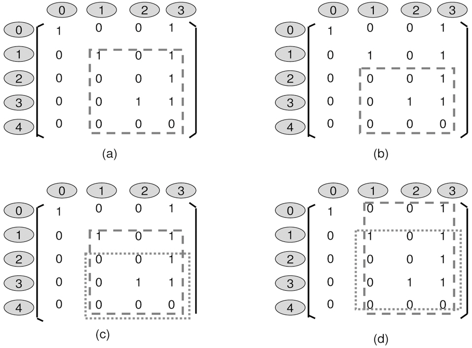
3. line 18: At any column, if we cannot find ’0’ at the starting position, then do not build the left leaf and the rest of its children. Here, the starting position is defined as the next immediately available position. E.g. in Fig. 4a, if the parent position reaches (0,0), then the starting position for its child is (0,1). Next, we need to introduce 1- (sub-) matrix, as seen in Fig. 4a, a 1- (sub-) matrix is defined as the element at the left-top corner of a matrix, being’1’. So does 0- (sub-) matrix, as can been seen in Fig.4b. Now, we can see that the longest path of a 0- (sub-) matrix is less than or equal to a 1- (sub-) matrix if 0- (sub-) matrix is a sub-matrix of 1- (sub-) matrix. E.g. in Fig. 4c, 1- (sub-) matrix in the dotted box has a longest path of 3, which is greater that the longest path of 0- (sub-) matrix in the dotted box. However, if a 1- (sub-) matrix is a sub-matrix of a 0- (sub-) matrix, then the longest path of a 1- (sub-) matrix is not necessary less than a 0- (sub-) matrix, as can be seen in Fig. 4d.
2) Example to Find Maximum Interference:
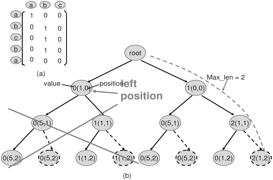
In this section, we use Figs. 5-7 to illustrate how to build the example into a binary tree and how to detect the longest path.The steps are as follows,
1. Starting from the root. Add two leaves. Always use the right leaf to seek the first 1 in the column and left leaf to seek 0
2. Build the right leaf. From previous position, move to the current column. From top-to-bottom, seek the first occurrence 1, and remember this position as the current position. Specifically, if a 1 is found, update the value of the current leaf. The value equals to the value of the parent node plus 1. If no 1s can be found, the branch should not proceed. In the example shown in Fig. 5, the right leaf finds position (0,0) is a 1, then updates its value to 0+1, which is 1.
Meanwhile, update the current leaf position to (0,0).
3. Build the left leaf. The left leaf seeks the 0 in a column at the starting position. At the starting position, if ’01 occurs, remember this position as the current position. If no 0 is present at the starting position of this column, then the program no longer construct leaves from this leaf.
4. Build leaves recursively. Build the leaves until no column left.
3) Prune-leaf Example:
In Fig. 8, after constructing the first right path, the
>
B. Integer Linear Programming for WCET
A major drawback for Trimaran [15] is that it is a proceduralbased framework. This makes inter-procedure analysis and optimization very difficult. We build a stand-alone ILP constraint analyzer based on the work of [4] to support Trimaran with ILP. Major extensions of work [4] that support Trimaran are interprocedure analysis, L2 cache ILP support and path re-construction. The following steps are described.
1. Procedure Name Resolution. We extend ELCOR of Trimaran, so that it exports CFG of each procedure and explicitly specifies the target name of each branch2. This information then is read as input for our program to perform interprocedure analysis.
2. Global Control Flow Graph. After the target name of the branch is resolved, the Global Control Flow Graph is constructed, which embeds all the procedures into the control flow graph of the main procedure.
3. Static Cache Analysis. Static Cache Analysis first labels the line block of the Global Control Flow Graph, and second, determines the conflicting line blocks for each cache line.
4. Cache Conflict Graph. The cache conflict graph is constructed based on static cache analysis. It is used to generate the cache constraints.
5. Object Function. The object function is re-written by considering the cost of both L1 and L2 cache misses.
6. Flow Constraints. The flow constraints are derived from structural constraints.
7. Functional Constraints. The functional equations are produced based on the Global Control Flow Graph, which mainly focuses on the relationship between the number of execution times of each basic block and its associated loop body.
8. ILP solver. We use a commercial ILP solver -CPLEX to solve the ILP problem.
9. Path re-construction. Based on the results from ILP solver, we derive the WCET path and L2 access sequence along the WCET path. This information serves as input to our L2 interference analyzer.
Details of ILP and implementation are outside the scope of this paper. They can be found in [4-6].
Our final WCET calculation is the sum of WCET of a single thread calculated by ILP and analyzed L2 inter-thread penalties.
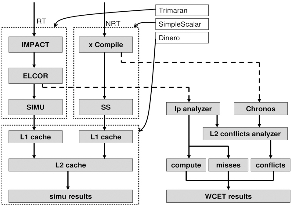
The WCET analysis for our proposed approach is based on four components, a) a heterogeneous dual-core simulator, b) a LP analyzer, c) a L2 conflict analyzer and d) Chronos [16]. The heterogeneous dual-core simulator is constructed by extending Trimaran 3.7 [15], SimpleScalar 2.0 [15], and Dinero IV [16]. In Fig. 9, Trimaran simulates very long instruction word (VLIW) architecture and SimpleScalar simulates Scalar architecture. Both use Dinero to simulate the memory hierarchy. Each core is implemented using a thread that can be spawned simultaneously at run-time to simulate a dual-core processor. A cache access buffer is implemented to synchronize the accesses from different cores to the caches. In our experiment, memory is configured as in Table 1, our VLIW processor contains four IALUs, two FPUs, one Ld/St, one Branch unit and 32 registers. Our Scalar processor is configured as an in-order 4-issue
[Table 1.] Configuration of the dual-core chip memory hierarchy
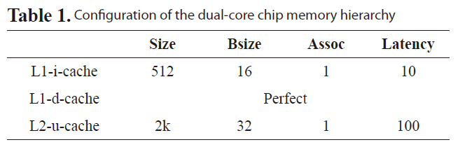
Configuration of the dual-core chip memory hierarchy
processor. The LP analyzer is implemented and incorporates a commercial ILP solver -CPLEX to handle the VLIW core linear programming analysis, which generates WCET compute cycles, number of misses for both L1 cache and L2 cache and the L2 access sequences.
In our experiments, we compare our interference matrix (IM) approach to simulated average-case performance and IM with the control flow (CF) based approach in [7]. Results show IM can achieve much tighter bound for WCET. The benchmarks are selected from Malardalen WCET benchmarks [17] and mediabench [18]. Table 2 lists the salient characteristics and description for these benchmarks. In the experiments, we choose ten real-time benchmarks from M
2Trimaran uses BRL instruction to call the procedure and the target address is stored in a branch register calculated by instruction PBRR.
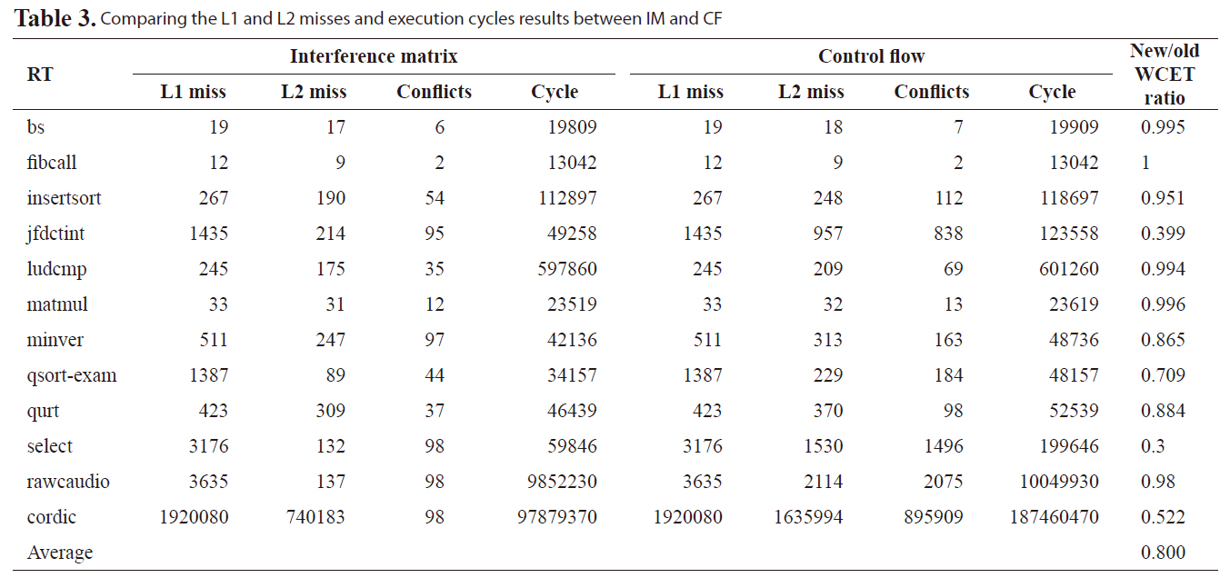
Table 3 compares the normalized WCET cycles between IM
[Table 2.] Salient Characteristics for Malardalen WCET benchmarks and Mediabench
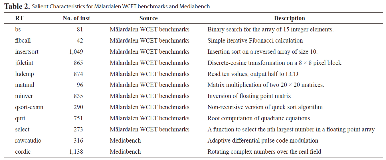
Salient Characteristics for Malardalen WCET benchmarks and Mediabench
[Table 3.] Comparing the L1 and L2 misses and execution cycles results between IM and CF

Comparing the L1 and L2 misses and execution cycles results between IM and CF
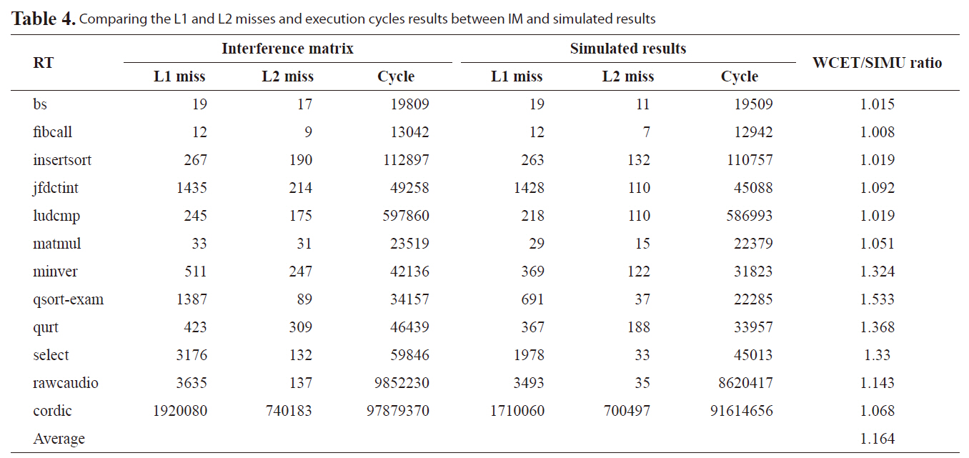
Comparing the L1 and L2 misses and execution cycles results between IM and simulated results
in this paper and AM in [7]. The results are organized to show the number of L1 misses, the number of L2 misses, the number of conflicts, estimated execution cycles and the normalized ratio between our new approach and the previous work. On average, the new approach improves WCET analysis by 20.0% compared to our previous approach. Especially, for benchmarks with large L1 misses, a very tight bound can be achieved, such as benchmark jfdctint, qsort-exam, select, rawcaudio, and cordic. The main reason for this tighter bound is our previous work does not consider the timing information of L2 accesses. This leads to a too conservative estimate for the number of L2 cache misses, especially for benchmarks with high L2 accesses but low L2 misses.

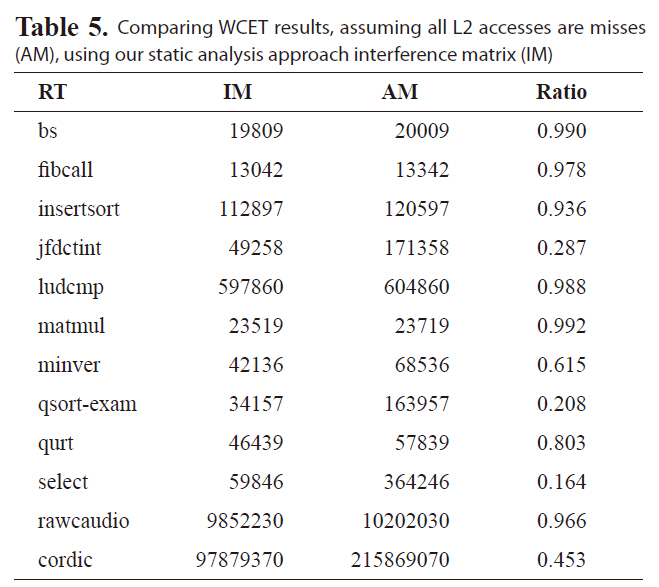
Comparing WCET results assuming all L2 accesses are misses (AM) using our static analysis approach interference matrix (IM)
We also compare the new approach and the simulated results to observe the effectiveness of our new approach. Table 4 shows the number of L1 misses, the number of L2 misses, the execution cycles and the normalized ratio between our new approach and the simulated results. We notice that for benchmark, such as fibcall, we can obtain a tight bound less than 1% overestimation and an overall average overestimation of 16.4%. Therefore, the proposed approach gives a much tighter and more effective WCET on the real-time threads for multi-core processor with shared L2 instruction cache.
An obvious solution is either to disable the shared L2 cache or assume all misses for L2 accesses, which provides the reference values to which we compare the results of our analysis

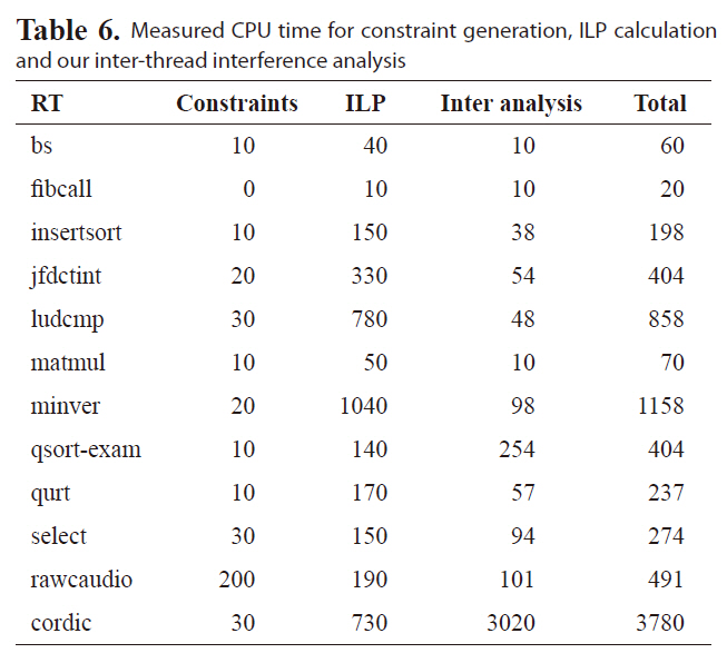
Measured CPU time for constraint generation ILP calculation and our inter-thread interference analysis
due to the difficulty of analyzing the inter-thread cache interferences and bounding the worst-case performance of the shared L2 caches in a multi-core chip. Table 5 compares the estimated WCET, assuming all L2 accesses are misses with the WCET estimated by our approach. As can be seen, by statically bounding the L2 cache instruction interferences, the estimated WCET cache instruction interferences, the estimated WCET is much smaller than the results, assuming all the L2 accesses are misses, indicating the enhanced tightness of WCET analysis.
We also measure the program run time on a desktop with 1.86GHz Core2 Due processor and 2G RAM running Red Hat Enterprise Linux 3. Table 6 shows the CPU time spent on different stages. The
Our recent work [7] first examined the timing analysis of shared L2 instruction caches for multi-core processors. In the paper, we proposed to exploit program control flow information of each thread to safely and efficiently estimate the worstcase L2 instruction cache conflicts. Although our experimental results show that the estimated WCET is not too far from the observed WCET for most benchmarks, overestimation is too pessimistic for some benchmarks. A close look reveals that overestimation mainly comes from three sources. First, the worst-case execution counts of basic blocks are often larger than the actual execution counts. Second, the cache static analysis approach [19] used for the L1 cache instruction cache analysis is very conservative. Third, our static L2 instruction miss analysis does not consider the timing of interference from other threads.
In this paper, we employ a time predictable architecture [20]
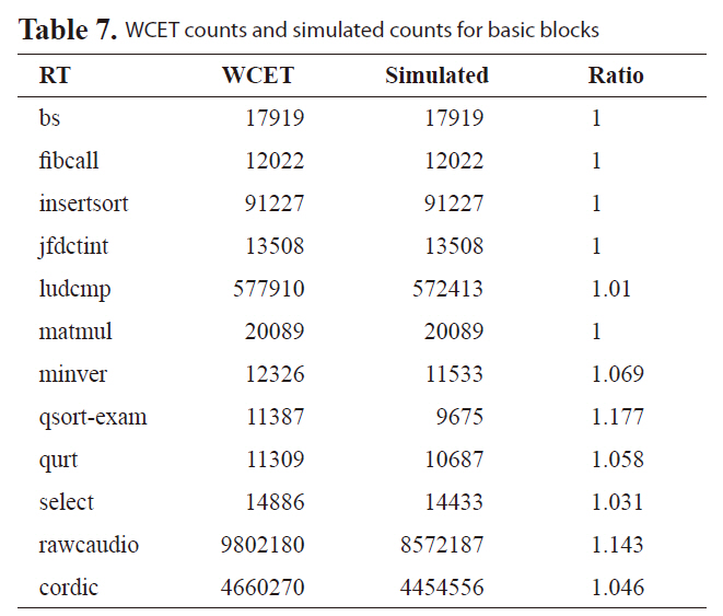
[Table 7.] WCET counts and simulated counts for basic blocks

WCET counts and simulated counts for basic blocks
to improve the worst-case execution counts for basic blocks to address the first overestimation. This architecture [20] is incorporated into our framework, as in Fig. 9. From Table 7, it can be seen that zero overestimation is achieved for basic block counts for most of the benchmarks{bs, fibcall, insertsort, jfdctint, matmul}. Second, we derive our L2 access sequences using edge transition information directly from ILP calculation results. ILP exactly determines the WCET path and cache status along WCET path compared to the static cache analysis approach in [21]. Third, as proposed in this paper,we explicitly consider the timing of interference from all the threads.
This paper presented a novel and effective approach to bounding the worst-case performance of multi-core processor with shared L2 instruction caches. We propose to exploit the L2 access sequence information from different threads, which can be acquired by examining edge transition from the calculation results of ILP, to accurately estimate the runtime inter-core instruction interferences between different threads. In addition, a time predictable architecture framework is constructed to evaluate our approach. Our experimental results reveal that we can achieve a tight bound on average overestimation of 16.4% than observed simulated results and a more than 20% improvement than in [7]. In addition, most benchmarks studied in this paper can be computed within seconds to derive the WCET.
In our future work, we will extend our analysis to a greater number of cores. In addition, it would be interesting to study timing analysis for shared data caches and unified caches of multicore processors.