To prepare for a future Korean lunar orbiter mission, semi-optimal lunar capture orbits using finite thrust are designed and analyzed. Finite burn delta-V losses during lunar capture sequence are also analyzed by comparing those with values derived with impulsive thrusts in previous research. To design a hypothetical lunar capture sequence, two different intermediate capture orbits having orbital periods of about 12 hours and 3.5 hours are assumed, and final mission operation orbit around the Moon is assumed to be 100 km altitude with 90 degree of inclination. For the performance of the on-board thruster, three different performances (150 N with Isp of 200 seconds, 300 N with Isp of 250 seconds, 450 N with Isp of 300 seconds) are assumed, to provide a broad range of estimates of delta-V losses. As expected, it is found that the finite burn-arc sweeps almost symmetric orbital portions with respect to the perilune vector to minimize the delta-Vs required to achieve the final orbit. In addition, a difference of up to about 2% delta-V can occur during the lunar capture sequences with the use of assumed engine configurations, compared to scenarios with impulsive thrust. However, these delta-V losses will differ for every assumed lunar explorer's on-board thrust capability. Therefore, at the early stage of mission planning, careful consideration must be made while estimating mission budgets, particularly if the preliminary mission studies were assumed using impulsive thrust. The results provided in this paper are expected to lead to further progress in the design field of Korea’s lunar orbiter mission, particularly the lunar capture sequences using finite thrust.
In the current decade, numerous deep space missions have been newly planned and performed by various space agencies worldwide. Examples of these include Japan Aerospace Exploration Agency’s SELenological and ENgineering Explorer (SELENE)(Kato et al. 2008) and SELENE-II (Tanaka et al. 2008), China National Space Administration’s Chang’E-1 (Zheng et al. 2008) and Chang’E-2, Indian Space Research Organization ’s Chandrayaan-1 (Goswamia & Annaduraib 2008) and National Aeronautics and Space Administration (NASA)’s Lunar Reconnaissance Orbiter (LRO) (Chin et al. 2007). In addition to these missions, the biggest rover mission ever flown to Mars, NASA’s Mars Science Lab mission, is ready to launch in 2011. Unlike previous missions undertaken during the 1950s through 1970s, recent missions have emphasized international collaboration. Current worldwide deep space missions, including robotic missions,are also focused on sending humans to Mars, or to asteroids and beyond. In keeping with these trends, Korean Astronautical Society has extended their interest further to planetary exploration, and for this reason, numerous related basic studies have been widely performed, particularly focused on a lunar mission.
With impulsive high thrust, Song et al. (2008) developed the lunar mission design software, and designed an optimal Earth-Moon transfer trajectory using direct departure from a circular initial Earth parking orbit. Later,Song et al. (2009c) presented various optimal Earth-Moon transfer trajectories using intermediate Earth departing loop orbits by upgrading the previously developed software. An Earth-Moon transfer trajectory design considering a spacecraft’s visibility from a Daejeon ground station at both the trans lunar injection (TLI) and lunar orbit insertion (LOI) maneuvers is also conducted by Woo et al. (2010). Works done by Song et al. (2009c) and Woo et al. (2010) assumed an impulsive thrusting method to design an Earth-Moon transfer trajectory. For Earth-Moon transfer trajectories with low thrust, Lee & Bang (2007) derived optimal low thrust trajectory solutions with simplified 2-dimensional flight dynamics. Later, Song et al. (2009b) presented optimal Earth-Moon transfer trajectories using both the constant and variable low thrust with more complicated flight dynamics, 3-dimensional problem and with 3rd body perturbations. Song et al. (2009a) also proposed a lunar cargo mission design strategy using variable low thrust by combining both the analytical and numerical optimization method. In other design studies that were performed to prepare for Korea’s future lunar mission, Cho et al. (2010) presented trajectory correction maneuver for lunar mission trajectory based on 3-body dynamics, and No & Jeon (2010) performed an Earth-Moon transfer trajectory design using mixed impulsive and continuous thrust. To design missions with a spacecraft located in very close proximity to the Moon, Cho et al. (2009) analyzed optimal lunar landing trajectories with knowledge of parking orbits before the decent phase with assumptions of 2-dimensional problem, and later, Jeong et al. (2010) presented a precise planetary landing method with terrain aided inertial navigation. Song et al. (2010b) developed a precise lunar orbit propagator and analyzed the lunar polar orbiter’s lifetime, which is strongly affected by the Moon’s non-spherical gravitation and the Earth’s point mass perturbation.
In the preliminary trajectory design studies, it is common to assume that thrust burn occurs almost instantaneously when the thrust burn magnitude is very large, and the duration of the burn is very short compared to the overall mission transfer time. However, in reality, there indeed exists a short burn duration which leads delta-V losses during the thrust burn arcs. For a more realistic mission design, recent works done by Song et al. (2010a) presented Earth-Moon transfer trajectory design results using finite thrust. Their study assumed that a TLI maneuver is limited to have maximum thrust capability. Based on this assumption, Song et al. (2010a) designed 204an Earth-Moon transfer trajectory from the beginning of the Earth departure to the lunar closest approach. They found that about 2-5% of TLI delta-V magnitude differences may occur due to delta-V losses when compared to the delta-V of values derived with impulsive TLI maneuver.They also concluded that these losses should be considered at the early stage of lunar transfer trajectory design.
Before discussing the main objective of this work, it is important to keep in mind that there are generally four different mission phases for a lunar mission. First, a spacecraft performs a TLI maneuver to insert a spacecraft from the Earth parking orbit to the trans-lunar trajectory. Second, after TLI maneuver, a spacecraft coasts along in the trans-lunar trajectory. Third, a spacecraft performs LOI maneuver to be captured and orbit around the Moon. Finally, a spacecraft performs several de-orbit maneuvers to change its orbit from the captured orbit to a desired mission operational orbit at the Moon. The design study for an optimal lunar mission trajectory should be conducted, and must include these four different mission phases (Song et al. 2010a). As previous research done by Song et al. (2010a) was focused on analyzing delta-V losses due to the finite thrust only for TLI maneuver, the current work is conducted as an extension of previous research. Therefore, this work is only focused on the third and fourth phases among the four different lunar mission phases discussed above. It is assumed that the spacecraft is already located in the vicinity of the Moon, and thus the spacecraft’s states are expressed in the reference coordinate frame of the Moon centered Moon mean equator and International Astronomical Union vector of epoch J2000 (M-MME2000). For more detailed information on the M-MME2000 coordinate frame, readers may refer to literature by Song et al. (2010b).
The main goal of the current study is to find and analyze the delta-V losses due to the finite burn during lunar capture sequence. These delta-V losses may occur at executions of several LOI maneuvers which generally use the spacecraft’s on-board thruster. The 1st LOI maneuvers are performed to cause the spacecraft to orbit around the Moon, and following LOI maneuvers, or equally called apoapsis adjustment maneuvers (AAMs), are usually performed to adjust lunar capture orbits’ apoapsis altitudes.A spacecraft’s equations of motion are expressed under N-body dynamics including the Moon’s J2 effects. The final mission operational orbit around the Moon is assumed to be 100 km altitude with 90 degree of inclination,and is assumed to be achieved by two different intermediate capture orbits having orbital period of about 12 hours and 3.5 hours, respectively. For an on-board thruster’s performance, three different performances, 150 N with Isp of 200 seconds, 300 N with Isp of 250 seconds and 450 N with Isp of 300 seconds, are assumed, to enable a broad estimate of delta-V losses. In the subsequent sections of this paper, detailed dynamics used to formulate the semi-optimal lunar capture sequence are treated, and various simulated results are provided. Although only the simulation results of three different on-board thrusters are discussed, the results provided in this paper will offer numerous insights to the mission designers that will save time and effort. As it has been shown that various delta-V characteristics using finite burn at the lunar capture sequence can be well estimated (each de-orbit burn’s start time as well as its location, each burn’s duration and delta-V’s magnitude) from the optimized values with impulsive thrust, it is expected that results discussed in this work can support further progress in the design of Korea’s lunar orbiter mission, particularly the lunar capture sequences using finite thrust.
2. CAPTURE ORBIT DESIGN USING FINITE THRUST
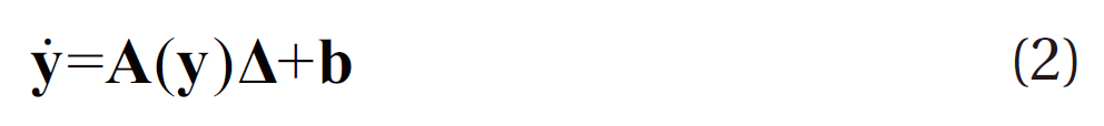
The equations of motion for a spacecraft flying in the vicinity of the Moon can be expressed in terms of modified equinoctial orbital elements, as shown in Eqs. (1)-(3). Since the modified equinoctial orbital elements are valid for circular, elliptic, and hyperbolic orbits, and also exhibit no singularity for zero eccentricity, for orbital inclinations equal to 0 degree and 90 degree, the set of modified equinoctial orbital elements is widely used for trajectory analysis and optimization (Betts 2010).
where y and ?represent spacecraft’s state vectors and their derivatives expressed with modified equinoctial orbital elements, and
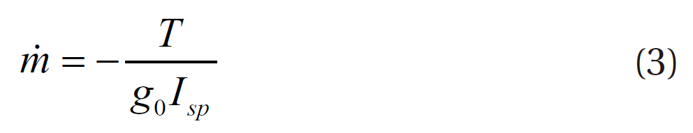
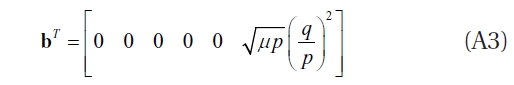
The total non-two-body acceleration vector can be included in Δ terms, in Eq. (2), with Eq. (3) as follows:
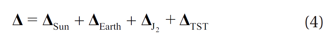
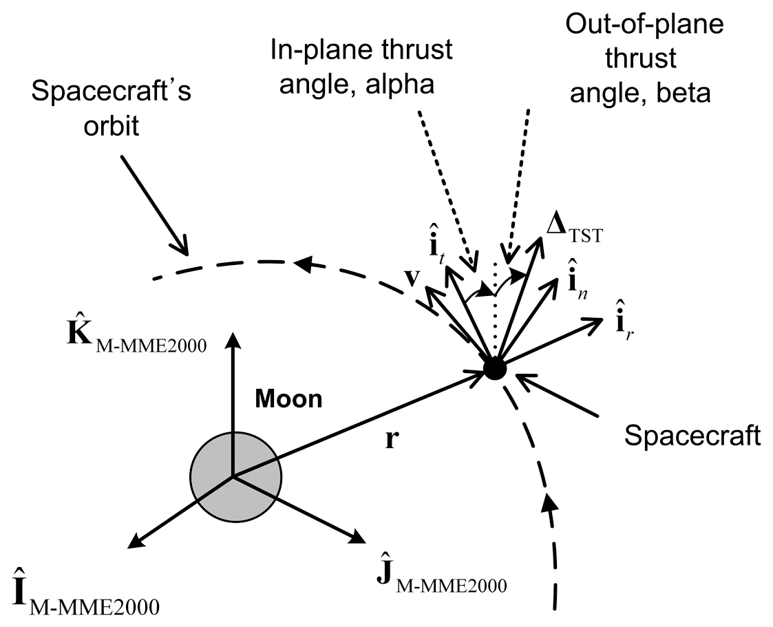
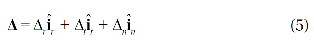
In Eq. (4), Δsun is the disturbing acceleration due to the point mass of the Sun, ΔEarth is due to the point mass of the Earth, ΔJ2 is due to body’s oblate effect, in this work the Moon, and ΔTST is the disturbing acceleration caused by the thrust, respectively. The total non-two-body acceleration vector, Δ, shown is Eq. (4), can also be expressed with the unit vectors as in Eq. (5) (Betts 2010).
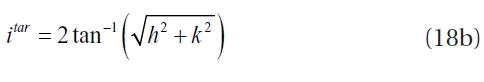
where i
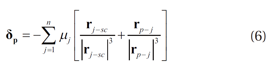
Secondary body accelerations, expressed in Eq. (4) with Δsun and ΔEarth, can be derived based upon the Cartesian coordinate system (δp) as in Eq. (6) (Vallado & McClain 2007).
where
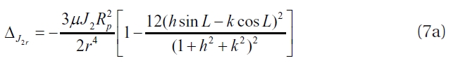
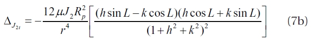
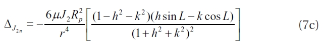
In Eq. (7),
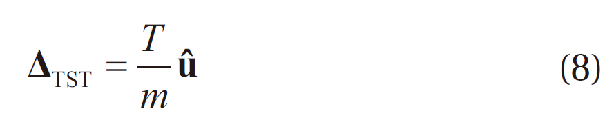
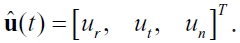
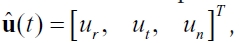
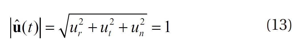
where T is the thrust magnitude, m is the spacecraft mass and u is the unit pointing thrust vector expressed in the spacecraft centered radial-tangential-normal coordinate system. The unit pointing thrust vector is defined by the time varying control vector
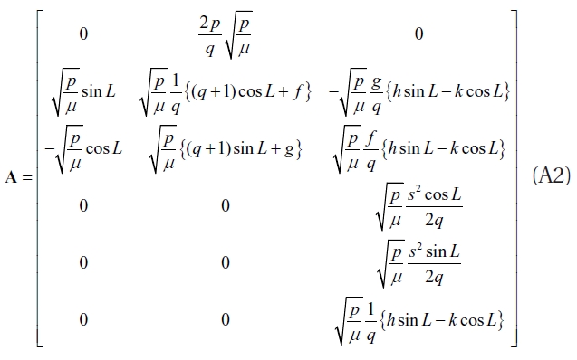
Some of the other useful equations for the equations of motion are presented in Appendix A.
2.2 Formulating the Optimal Control Problems
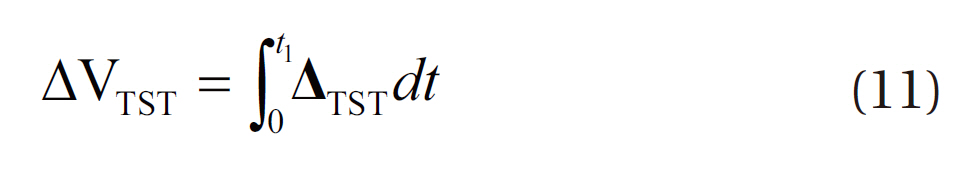
As the finite burn is assumed to capture a spacecraft around the Moon, every capture orbit can be modeled using two distinct phases. The first phase is where de-orbit burn is activated, called the burn arc or burning phase, and the second phase is called the coasting phase, in which a spacecraft flies without any acceleration due to the thrust. Hereinafter, these will be referred to as ‘phase 1’ for the burning phase and ‘phase 2’ for the coasting phase in each intermediate capture orbit, respectively. Thus, if two different intermediate loop orbits are used to insert the spacecraft into the final mission operational orbit, there will be three distinct burning and coasting phases for the successful entire lunar capture sequence. For each intermediate capture orbit, the performance index is given to simultaneously minimize overall delta-V magnitudes achieved by finite thrust, ?ΔVTST?, and spacecraft’s perilune approach velocity magnitude at the end of phase 2, ?Vperilune?, as shown in Eq. (9).
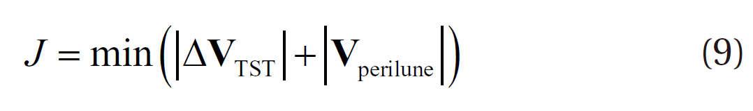
In the performance index, a spacecraft’s perilune approach velocity condition is also included, since the perilune approach velocity directly affects the next delta-V magnitude.
where
Phase 2’s duration,
are given as other control variables, with the following boundary conditions:
where superscript
Although the magnitude of unit pointing thrust vector is constrained by Eq. (13), boundary conditions for each component of unit pointing thrust vector shown in Eq. (12) are still needed during the optimization process to enhance the efficiency of convergence. Usually, these bounds are given as -1.01 and 1.01 for lower and upper bound, respectively (The Boeing Company 2010).
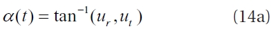
Using three components of unit pointing thrust vector,finite burn directions including in-plane angle
velocity axis to the projected thrust acceleration vector onto the orbit plane, and the out-of-plane thrust angle
For boundary conditions for the components of modified equinoctial orbital elements and the spacecraft’s mass shown in Eq. (1), appropriate conditions should be properly given, as in Eq. (15).


In Eq. (15), superscript


where subscript i and j denote the phase number, 1 and 2, and superscript ‘-’ and ‘+’ denote each phase’s start and end time, respectively.
For final terminal conditions at each intermediate capture orbit, three final equality conditions are given to target the user-defined orbit conditions, as shown in Eq. (17).


where
To roughly estimate the finite burn duration and the spacecraft’s fuel mass budget required for initial guesses of the given problem, optimized delta-V magnitude with impulsive thrust can be usefully applied to derive these estimates, as shown in Eq. (19).
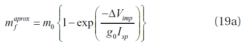
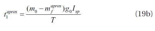
In Eq. (19),
3.1 Numerical Implications and Presumptions
To numerically optimize the established problem, the transcription method is used via the Sparse Optimal Control Software (SOCS) software developed by Boeing Company (2010). SOCS is widely used for aerospace trajectory optimization problems, particularly for trajectories with low thrust propulsions. One of the key aspects of the SOCS software is that a “mesh refinement” algorithm is adapted to estimate and reduce the errors while performing the discretization of the given trajectory dynamics that could seriously affect the accuracy of the final solutions (Betts 2010). For various constants used to establish the spacecraft’s dynamics, gravitational constant of the Moon is assumed to be about 4,902.800 km3/s2, for the Earth 398,600.441 km3/s2, for the Sun 13,271,244,207.6 km3/s2, radius of the Moon is assumed to be about 1,738.2 km, and J2 coefficient for the Moon is assumed to be about 0.2027e-3. For planetary ephemeris, Jet Propulsion Laboratory’s DE405 is used to provide accurate position and velocity for given planets (Standish 1998).
To design a hypothetical lunar capture sequence, as with Lunar Prospector mission (Lozier et al. 1998) and other previous research (Song et al. 2008, 2009c, Woo et al. 2010), two different intermediate elliptical capture orbits having orbital periods of about 12 hours and 3.5 hours are assumed. Also, final mission operation orbit around the Moon is assumed to be 100 km altitude and 90 degree of inclination, with orbital period of about 118 minutes. However, to achieve results that are reasonably comparable with the previous research by Song et al. (2009c), each capture orbit’s orbital period is given as about 12.235 hours, 3.525 hours and 117.848 minutes, respectively. For on-board thruster’s performance, three different performances,150 N with Isp of 200 sec, 300 N with Isp of 250 seconds and 450 N with Isp of 300 seconds, are assumed, to provide a broad range of estimates of delta-V losses. These assumptions are made based on performances of the current main engines of other countries used for orbital maneuvering at the Moon, i.e., about 320 N with Isp of 200 seconds for NASA’s LRO and about 500 N with Isp of 300 seconds for JAXA’s SELENE. Therefore, the future Korean lunar explorer’s main engine performances for orbital maneuvering at the Moon may have different capabilities, as is assumed in this paper.
3.2 Case Studies with Different Finite Thrust Capabilities
In this section, various simulation results for delta-V losses during the lunar capture sequence with finite thrust are shown. For on-board thruster’s performance, three different performances, 150 N with Isp of 200 seconds, 300 N with Isp of 250 seconds and 450 N with Isp of 300 seconds, are assumed to provide a broad range of estimates of delta-V losses. As two different intermediate capture orbits are assumed, three different de-orbit maneuvers will be performed to insert the spacecraft into the final mission operational orbit around the Moon. The first maneuver will insert a spacecraft from the lunar arrival hyperbolic orbit to the 1st elliptical capture orbit having orbital period of about 12 hours, the second maneuver will insert a spacecraft from the 1st elliptical capture orbit to the 2nd elliptical capture orbit having orbital period of about 3.5 hours, and finally the third maneuver will insert a spacecraft from the 2nd elliptical capture to the final mission operational orbit around the Moon. To derive the initial spacecraft states at the time of 1st LOI execution, which are arbitrarily selected, backward propagation is performed with the perilune arrival conditions derived in Song et al. (2010a)’s work. Of the Earth-Moon transfer trajectories designed with several TLI maneuver capabilities in Song et al.’s (2010a) work, trajectory solutions derived with kick motor’s nominal performance, a maximum thrust of about 9.8 tons, is selected to obtain final lunar approach conditions for this work. Furthermore, this is the case when guaranteeing a spacecraft’s visibility from Daejeon ground station while executing TLI maneuver at Earth departure. To generate initial spacecraft states at times of other (i.e. 2nd or 3rd LOI maneuver) finite burn ignition points, perilune’s semi-optimal states derived on the previous capture orbit are selected, and again backward-propagated to the arbitrary selected time. The purpose of these arbitrary selections is to show the variety of finite burn characteristics compared to the solutions with impulsive thrust, and this assumption leads the presented results to be a semi-optimal solution. In subsequent discussions, every de-orbit burn ignition time will be expressed with a ‘-’ sign, which denotes the time before perilune approach at each capture orbit around the Moon.
3.2.1 Results for 150 N with Isp of 200 seconds
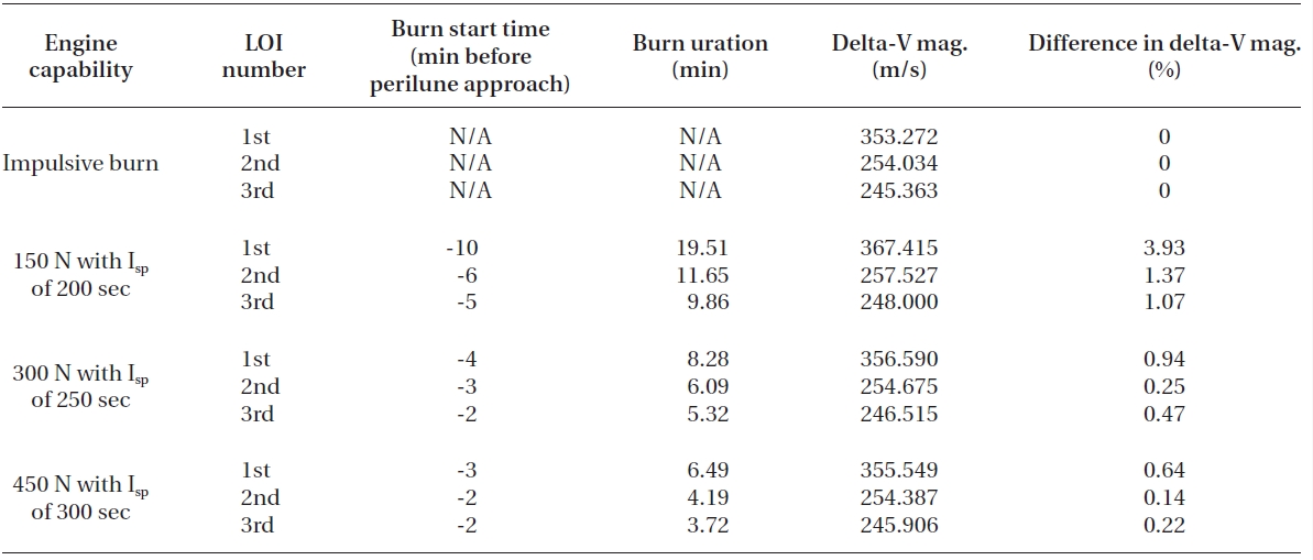
For first analysis, the on-board engine’s capability is assumed to have 150 N with Isp of 200 seconds for orbital maneuvering at the Moon. The spacecraft’s initial states for 1st LOI ignition time are derived based on the spacecraft’s states derived by Song et al. (2010a). Remember that a spacecraft’s first perilune approach was already successfully made for the epoch of 20-Feb-2017 03:41:26 (TDB), satisfying altitude of 100 km with 90 degree inclination in M-MME2000 frame. Also, overall mass at the perilune arrival was about 524.895 kg (only spacecraft’s dry mass + fuel) excluding the kick motor’s dry mass, which was about 315.422 kg. The kick motor’s dry mass is derived using the kick motor’s fuel mass and structure ratio given by Song et al. (2010a). Table 1 shows the simulation results for the 1st LOI maneuver with six different ignition points (before 1st perilune approach) using finite thrust. The 1st LOI maneuver will insert the spacecraft from the lunar arrival hyperbolic orbit into the 1st elliptical capture orbit, which has an orbital period of about 12 hours. Note that all delta-V characteristics for impulsive thrust shown in this work are referred to from Song et al. (2009c)’s work. Of the three different mission scenarios derived by Song et al. (2009c), those derived with departing year of 2017, and which assumed direct TLI from the circular Earth parking orbit, were selected as cases for comparison. For Korea’s hypothetical first lunar orbiter mission in 2017, Korea Space Launch Vehicle-II (KSLV-II) was assumed as the launch vehicle, with an on-orbit capacity of 2.6 tons, at 300 km altitude, with 80 deg inclined circular Earth parking orbit.
As shown in Table 1, differences in the 1st LOI burn start location significantly affect the delta-V magnitude required to insert the spacecraft to the next capture orbit around the Moon. To minimize delta-V magnitude, it can be concluded that 1st LOI burn must be started, on the lunar arrival hyperbolic trajectory, at around about 10 minutes before perilune’s arrival. For this case, delta-V loss is found to be about 14.14 m/s (about 3.93%) when compared to the delta-V’s magnitude derived with impulsive thrust. Also, about 19.5 minutes of continuous de-orbit burn is required to insert the spacecraft into the 2nd capture orbit. After burn out of 1st LOI maneuver, spacecraft mass is found to be about 434.471 kg, which means about 90 kg of fuel is required to perform 1st LOI maneuver with the given engine capability. An interesting fact that was discovered is that the estimated finite burn duration (shown with Eq. (19)) using impulsive delta-V is found to be about 18.82 minutes, and almost half the value of this estimated finite burn duration (about 9.5 minutes) nearly matches the best burn start time derived in Table 1. After about 12 hours, a spacecraft again encountered perilune, the 2nd perilune approach, at the
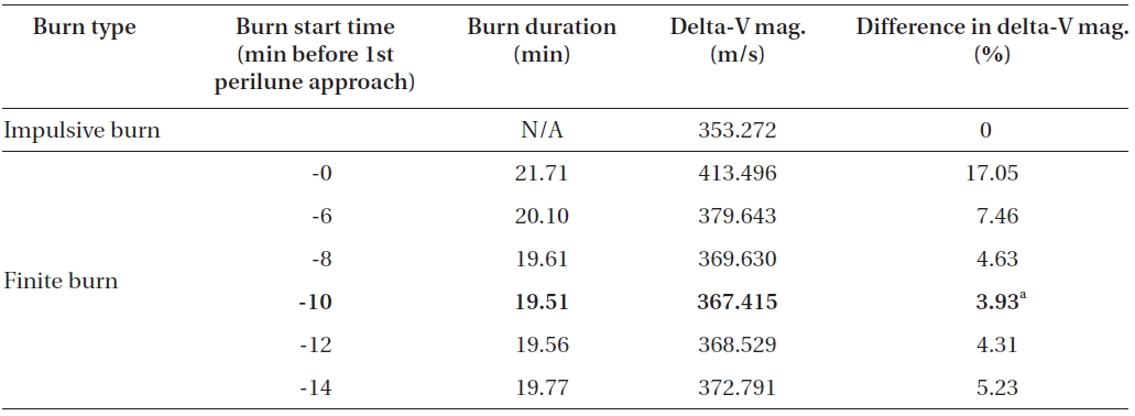
Delta-V comparisons for the 1st LOI maneuver (arrival hyperbolic trajectory to 1st 12 hour elliptical capture orbit) between the impulsive thrust and the finite thrust (150 N with Isp of 200 seconds) with different delta-V ignition points.
epoch of 20-Feb-2017 15:55:33 (TDB) and ready for the 2nd LOI (1st AAM), to reduce its apolune radius.
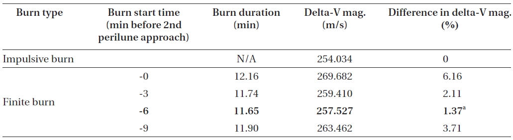
The execution of the 2nd LOI will put a spacecraft into the 2nd elliptical capture orbit, which is assumed to have orbital period of about 3.5 hours. Just like the 1st LOI maneuver ignition point derivations, initial spacecraft’s states for the 2nd LOI are derived using the closest approach conditions that have already been derived, the best case, in Table 1. Delta-V derivation results for the 2nd LOI maneuver, with four different maneuver ignition points using finite thrust, are shown in Table 2. The 2nd LOI maneuver will take place nearly at the end of the 1st elliptical capture orbit, before 2nd perilune approach.
From the results shown in Table 2, the 2nd LOI burn must be started at about -6 minutes before 2nd approach of perilune, the best case, near the end of the 1st 12-hour capture orbit. De-orbit finite burn’s duration in this scenario is found to be about 11.65 minutes, with Delta-V loss about to be 3.49 m/s (about 1.37%) when compared to the delta-V’s magnitude derived with impulsive thrust. The estimated finite burn duration using impulsive delta-V is found to be about 11.50 minutes, and almost half of this estimated duration again nearly matches the best burn start time derived in Table 2. After successful burn of the 2nd LOI, spacecraft mass is about 381.005 kg, which means about 53 kg of fuel is required for the 2nd LOI maneuver. After about 3.5 hours, spacecraft again approached perilune at the epoch of 20-Feb-2017 19:27:05 (TDB), the 3rd time, and is ready for the 3rd LOI to insert a spacecraft to the final mission operational orbit.
To analyze the final de-orbit maneuver (3rd LOI) characteristics using finite thrust, the same strategy is used as in the previous analysis. Spacecraft’s initial states for the

Delta-V comparisons for the 2nd LOI maneuver (the 1st 12 hour elliptical capture orbit to the 2nd 3.5 hour elliptical capture orbit) between the impulsive thrust and the finite thrust (150 N with Isp of 200 seconds) with different delta-V ignition points.
Delta-V comparisons for the 3rd LOI maneuver (the 2nd 3.5 hour elliptical capture orbit to the final circular mission operational orbit) between the impulsive thrust and the finite thrust (150 N with Isp of 200 seconds) with different delta-V ignition points.
Delta-V comparison results between the impulsive and the finite thrust. On-board engine’s capability is assumed to have 300 N and Isp of 250 seconds. Every three (1st 2nd and 3rd LOI) different de-orbit maneuvers’ start time durations magnitudes and their differences in percentage rates are presented with arbitrarily selected different delta-V ignition points. The best solutions are highlighted with bolded characters.
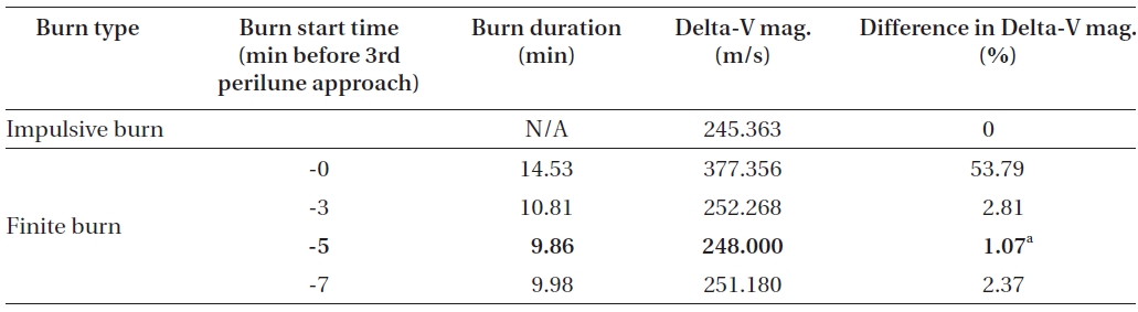
3rd LOI maneuver ignition time are again derived using backward propagation with the closest approach conditions,the best case, in Table 2. In Table 3, delta-V derivation results for the 3rd LOI maneuver, with four different maneuver ignition points using finite thrust, are shown.
To minimize delta-V magnitude for the 3rd LOI burn, ignition of 3rd LOI must be started at about -5 minutes before 3rd approach of perilune, on the 2nd 3.5 hour capture orbit. Finite burn duration in this scenario is about 9.86 minutes with delta-V loss of about 2.64 m/s (about 1.07%) when compared to the delta-V magnitude derived with impulsive thrust. Almost half the value of estimated burn duration (estimated: about 9.76 minutes, half of estimated: about 4.88 minutes) with impulsive delta-V again nearly matched the best burn start time as derived in Table 3. After a successful burn of the 3rd LOI, spacecraft mass delivered to the final mission operational orbit is found to be about 335.750 kg, which means about 45 kg of fuel is required for the 3rd LOI.
According to the simulation results shown above, when only the best solutions are considered, delta-V losses of about 3.93, 1.37 and 1.07% will occur at each of three different lunar de-orbit maneuvers. Overall magnitude of delta-V loss occurring during a lunar capture sequence in this scenario is about 20.20 m/s, which is

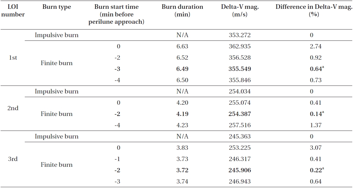
Delta-V comparison results between the impulsive and the finite thrust. On-board engine’s capability is assumed to have 450 N and Isp of 300 seconds. Every three (1st 2nd and 3rd LOI) different de-orbit maneuvers’ start time durations magnitudes and their differences in percentage rates are presented with arbitrarily selected different delta-V ignition points. The best solutions are highlighted with bolded characters.
about 2.12%. For fuel masses, a total of about 185.010 kg of fuel is required for finite thrust (including every LOI maneuver), and about 189.145 kg of fuel for impulsive thrust. Therefore, about 4 kg of fuel, about 2.24% more, is needed when the finite burn engine model is assumed. For thrust burn duration, it is found that about 41.02 minutes (about 19.51 minutes for 1st LOI, about 11.65 minutes for 2nd LOI and about 9.86 minutes for 3rd LOI) of de-orbit burn is required to achieve final mission operational orbit around the Moon in this scenario.
3.2.2 Results for 300 N with Isp of 250 seconds, and 450 N with Isp of 300 seconds
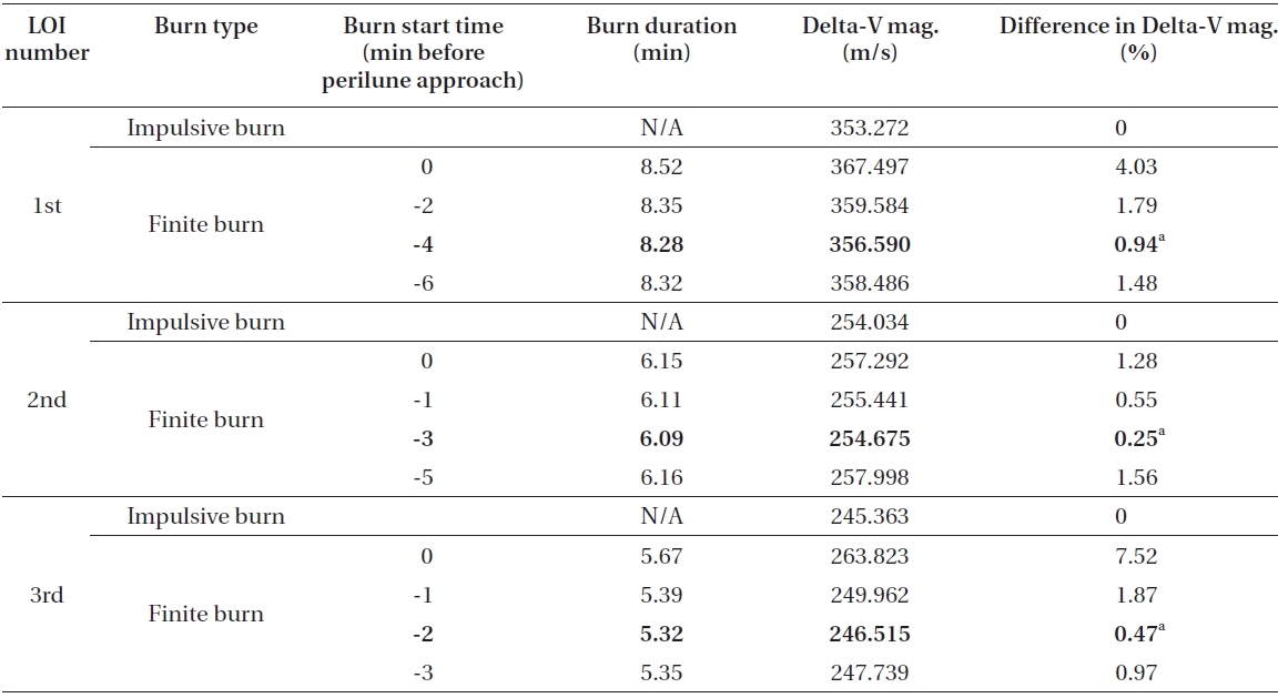
In this section, delta-V losses with engine’s capabilities of 300 N with Isp of 250 seconds and 450 N with Isp of 300 seconds are analyzed. As the most of the analyses are performed in the same manner as the case of 150 N with Isp of 200 seconds, only important mission parameters are provided in Table. 4 and 5. Table 4 shows the results for the delta-V losses that occurred during all lunar capture sequences with use of 300 N with Isp of 250 seconds. For 450 N with Isp of 300 seconds, results are shown in Table 5.
In Table 4, simulation results are shown for delta-V losses that occurred during the entire lunar de-orbit sequences with the use of 300 N and Isp of 250 seconds onboard engine. With this engine performance, it is found that about 5.11 m/s (3.32 m/s for 1st LOI, 0.64 m/s for 2nd LOI and 1.152 m/s for 3rd LOI) of delta-V loss will occur during the entire lunar capture sequence when capture orbits are assumed as they are in this paper. In terms of a percentage rate, 5.11 m/s is about 0.55. As expected, it can be easily observed that delta-V loss rates in this scenario are significantly reduced when compared to the results derived with the use of 150 N with Isp of 200 seconds on-board engine, which showed about 20.20 m/s (about 2.12%) loss. As in previous results discussed, for every three de-orbit maneuvers, almost half the value of estimated burn durations with impulsive delta-V again were close to matching the best burn start time. For the 1st LOI maneuver, half of estimated burn duration is about 4.21 minutes, while it is about 3.04 minutes for the 2nd LOI maneuver and about 2.65 minutes for the 3rd LOI maneuver.With on-board engine of 300 N with Isp of 250 seconds, about 19.69 minutes (about 8.28 minutes for 1st LOI, about 6.09 minutes for 2nd LOI and about 5.32 minutes for 3rd LOI) of overall burn duration is required to achieve the given operational orbit around the Moon. Final spacecraft’s mass is found to be about 369.289 kg, and this means that about 155 kg of fuel, about 34 kg less than the case in which on-board engine of 150 N and Isp of 200 seconds (about 189 kg) are used, is required to insert the spacecraft to the final operational orbit around the Moon. From a fuel consumption perspective, only about 0.9% of difference (about 154.146 kg of fuel for impulsive thrust and about 155.606 kg of fuel for finite thrust) is observed.
Table 5 summarizes the simulation results for every three (1st, 2nd and 3rd LOI) different de-orbit maneuvers to achieve a given lunar final operational orbit using 450 N and Isp of 300 seconds on-board thruster. With on-board engine having 450 N and Isp of 300 seconds, about 3.17 m/s (2.28 m/s for 1st LOI, 0.35 m/s for 2nd LOI and 0.54 m/s for 3rd LOI) of delta-V loss will occur during the entire lunar capture sequence, which is only about 0.33% when expressed as a percentage. From the results of three different engine performances that we have assumed,simple astrodynamic theory has again confirmed that as the finite burn engine’s performance increases, the trajectory solutions can be well approximated to the solutions that use impulsive thrust. However, if the finite burn engine’s performance is rather low, delta-V losses due to finite thrust must be considered at the early mission design stage or further detailed mission design phases. About 14.40 minutes (about 6.49 minutes for 1st LOI, about 4.19 minutes for 2nd LOI and about 3.72 min utes for 3rd LOI) of overall burn duration is required to insert a spacecraft into the final mission operational orbit in this scenario. Final spacecraft’s mass is found to be about 391.722 kg, which means about 133 kg of on-board fuel is required. For detailed fuel comparisons during all lunar capture phases, only about 1.2 kg of fuel (0.8%) difference (about 132.028 kg of fuel for impulsive thrust and about 133.192 kg of fuel for finite thrust) is observed in this scenario. To aid the understanding of readers, the main results of all different case studies given in subsection 3.2 are summarized in Appendix B with Table B1.
3.3 Example of a Lunar Capture Trajectory
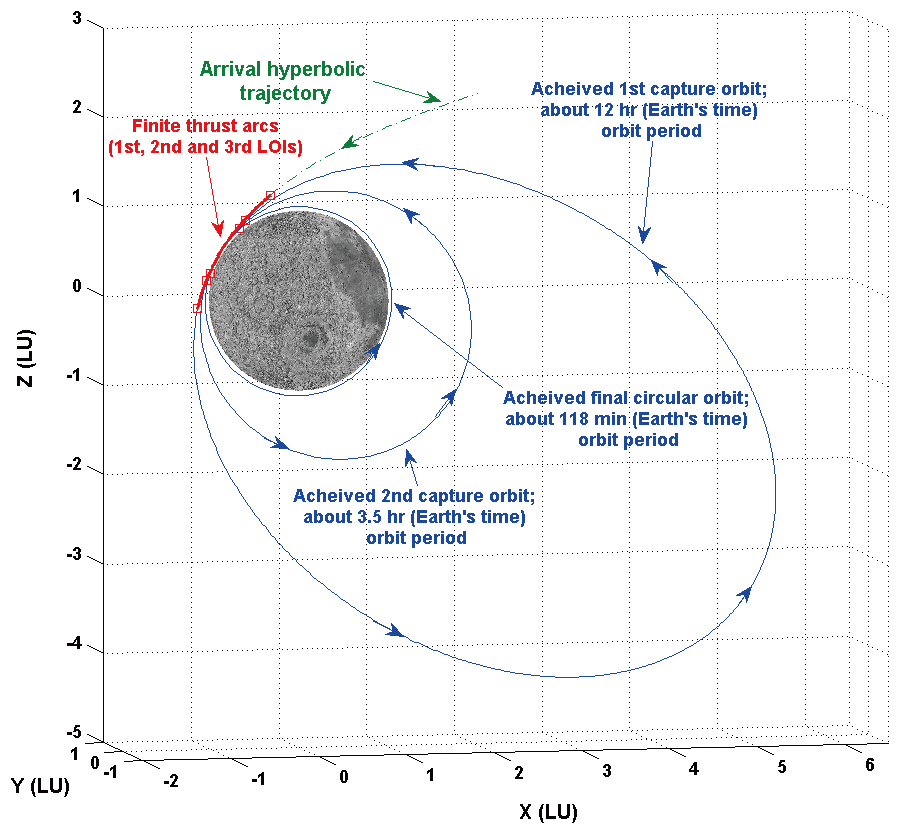
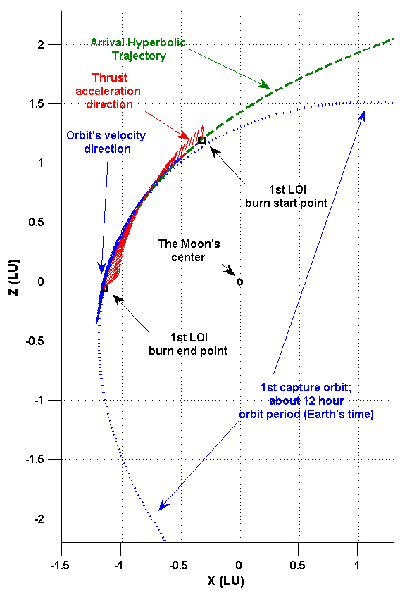
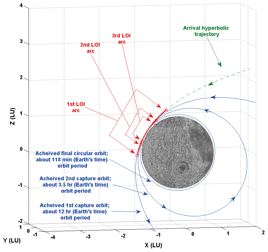
An example of a lunar capture trajectory using finite thrust is provided in this subsection. Of the several capture trajectories designed in subsection 3.2, the scenario with on-board engine capability of 150 N with 200 seconds Isp is shown as an example. To plot the entire lunar capture sequence, only the best solutions of finite burn ignition point, from Table. 1-3, are considered. Figs. 2 and 3 show the example of a lunar capture trajectory using finite thrust. In Fig. 2, the entire lunar capture elliptical orbit, including arrival hyperbolic trajectory, is shown with finite burn arcs. Fig. 3 is the zoomed view of Fig. 2, showing details of finite burn arcs. In both figures, every axis is scaled to have 1 lunar unit (LU), which is about 1,738.2 km. From Figs. 2 and 3, it can be easily observed that every finite burn-arc (1st, 2nd and 3rd LOI) sweeps almost symmetric orbital portions with respect to the perilune vector to minimize the delta-Vs required to achieve final orbit.
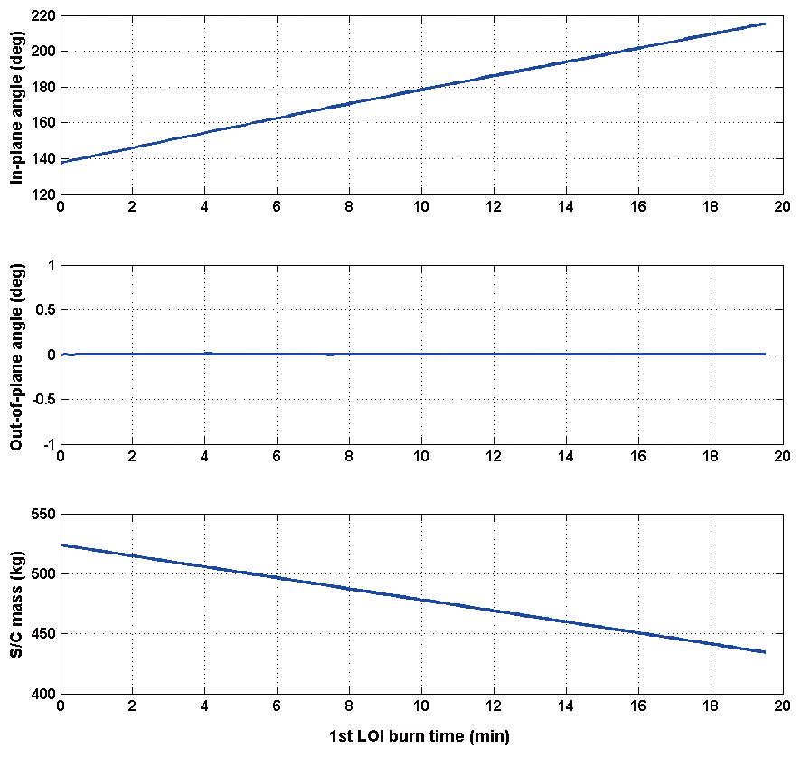
In Fig. 4, thrust steering angle and mass variation history for 1st LOI maneuver are shown. Note that thrust steering angles are expressed with respect to the spacecraft centered radial-tangential-normal coordinate system.During the 19.51 minutes of 1st LOI burn, in-plane thrust angle,
the spacecraft from the arrival hyperbolic trajectory to the 1st highly elliptical capture orbit around the Moon. Almost all of the first half of the in-plane thrust directions were varied in order to follow the spacecraft’s path from the arrival hyperbolic trajectory to the 1st highly elliptical capture orbit; then, in-plane thrust direction showed almost anti-parallel directions to the orbital velocity; and finally, in-plane thrust directions were again varied to achieve the 1st highly elliptical capture orbit’s path. Although only the 1st LOI burn arc is shown as an example, other de-orbit maneuvers (2nd and 3rd LOI) using finite thrust showed almost the same characteristics as the 1st LOI maneuver.
In this work, semi-optimal lunar capture orbits using finite thrust are designed and analyzed. Delta-V losses during lunar capture sequence due to finite thrusts are also analyzed by comparing those with the values derived with impulsive thrusts in previous research. To give a broad estimate of delta-V losses for mission designers, performances of three different on-board thrusters (150 N with Isp of 200 seconds, 300 N with Isp of 250 seconds, 450 N with Isp of 300 seconds) are assumed. As a result, several important mission parameter characteristics are discovered.First, it is found that up to about 2% of delta-V loss (0.33% loss with 450 N, Isp 300 seconds; 0.55% loss with 300 N, Isp 250 seconds; and 2.12% loss with 150 N, Isp 200 seconds) can occur during the lunar capture sequences if a finite thrust engine model is adapted. However, these losses will be dependent on the on-board engine’s performance. Second, estimated finite burn’s duration using optimized delta-Vs with impulsive thrust can be useful to determine the approximated finite burn ignition time. Half the value of estimated finite burn duration almost matches the best burn ignition time, which can be expressed as “time before perilune approach.” Third, as expected, the finite burn-arc sweeps almost symmetric orbital portions with respect to the perilune vector with appropriate thrust direction variations. This is due to the efficient insertion of a spacecraft into the desired capture orbit while minimizing the magnitude of delta-Vs. Therefore, at the early stage of mission planning, careful care must be taken while estimating mission budgets, especially if preliminary mission studies were performed using the impulsive thrust engine model. Although simulation results using the performances of only three different on-board thrusters are discussed, the results provided in this paper will give numerous insights to the mission designers, allowing them to reduce their time and effort. It is expected that the results discussed in this work will lead to further progress in the design field of Korea’s lunar orbiter mission, particularly the lunar capture sequence using finite thrust.
Appendix A
This Appendix rigorously addresses the issues used in equations of motion in the current study. The components of modified equinoctial orbital elements shown in Eq. (1) have relations to classical orbital elements as shown in Eq. (A1) (Walker et al. 1985).


where,
and
where


and
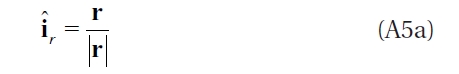
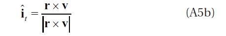
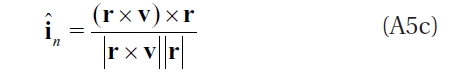
Unit vectors shown in Eq. (5) can be derived by using the inertial Cartesian position vector r and velocity vector v, as shown in Eq. (A5).
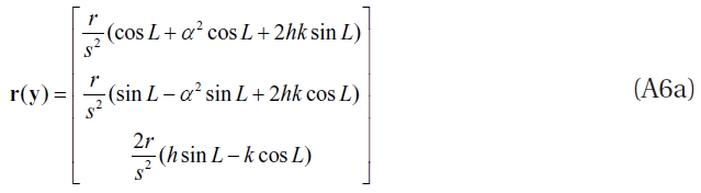
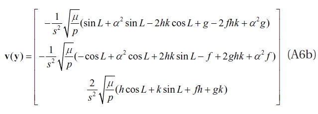
Also, equinoctial orbital elements y are related to the Cartesian states (r,v) according to the expressions (Betts 2010):
Appendix B
Main case study results simulated with different finite thrust capabilities (150 N with Isp of 200 seconds, 300 N with Isp of 250 seconds and 450 N with Isp of 300 seconds) are summarized in Table B1.

Summary of delta-V comparison results between the impulsive and the finite thrust. For each simulation cases only the best solutions are presented.
where