Korea Astronomy and Space Science Institute (KASI) launched the development project of two satellite laser ranging(SLR) systems in early 2008 after the government fund approval of the SLR systems in 2007. One mobile SLR system and one permanent SLR station will be developed with the completion of the project. The main objectives of these systems will be focused on the Space Geodetic researches. A system requirement review was held in the second half of the same year. Through the following system design review meeting and other design reviews, many unsolved technical and engineering issues would be discussed and resolved. However, the design of the mobile SLR system is a corner stone of whole project. The noticeable characteristics of Korea’s first SLR system are 1) use of light weight main mirror, 2) design of compact optical assembly, 3) use of KHz laser pulse, 4) use of commercial laser generator, 5) remote operation capability,6) automatic tracking, 7) state of art operation system, etc. In this paper, the major user requirement and pre-defined specification are presented and discussed.
From 1986, Korea Astronomy and Space Science Institute(KASI) had proposed and planned to introduce a satellite laser ranging (SLR) system for satellite tracking and orbit observation (Kim et al. 1987). The preliminary study on the current international technological status of SLR system, the feasibility study on the Korea’s first SLR system and tentative design requirements can be found in Park et al. (2005). Without a precise satellite tracking device in Korea, KASI has tried optical telescopes to track satellites. KASI has limited success on the tracking of low Earth orbit satellites and relatively better results on the monitoring geo-synchronous and medium Earth orbit satellites as seen in Choi et al. (2009). The importance of the SLR system for satellite tracking cannot be just emphasized for precise orbit determination rather re-evaluated for the fundamental device of Space Geodesy as in Pearlman et al. (2002). The historical review and the future challenge of SLR system are well presented in Degnan (1997).
Eventually, KASI can start the development project of two SLR systems from 2008 with the Korean government fund. The expected SLR system was named of the Accurate Ranging System for Geodetic Observation(ARGO) obviously from Greek mythology. The planned project period is from 2008 to 2014. However, it will be adjusted by the budget profiles of upcoming years from the government (Jo et al. 2009). We are currently designing two SLR systems, one for mobile usage and another for stationary observatory with bigger receiving telescope(1 meter). The suitable candidates for stationary SLR observatory will be verified by the year-long on-site meteorological observation. KASI organized a collaborating group of research institutes and universities for the ARGO development. Each members of the group is participating the developments of sub-systems of ARGO system. KASI is solely developing a operating system of ARGO system. Due to the lack of experience and developed technology, KASI has a close tie with the SLR observatory of Austrian Academy of Science for the development of real-time operating system of SLR system. Also, KASI and Shanghai Astronomical Observatory have been discussed and collaborative worked for the hardware system part of SLR system. The Space Geodesy community in Korea has been worked to join global scale observation and researches. Then KASI is expecting the completion of this project make Korea contribute the international SLR and Space Geodesy communities.
In this paper, the major user requirement, pre-defined specification and design concepts are presented and discussed. In Section 2, the main objectives of the development of SLR systems and the top level user requirements defined in previously researches (Kim et al. 2007) are reviewed briefly. The conceptual design philosophy and the brief description of sub-systems are presented in the Section 3. In Section 4, the components of the sub-systems and functionalities are described and explained. This paper is based on Jo (2009) and Jo et al. (2009).
The main objectives of mobile SLR system developments are;
1) Establishment of near Earth space monitoring capability as suggested in the national priority plan for science and technology
2) Acquisition of high precision orbit determination capability with mm grade range measurement to the laser retro reflector equipped satellites
3) Participation in international space geodetic research, Global Earth Observation System of Systems, and Global Geodetic Observing System
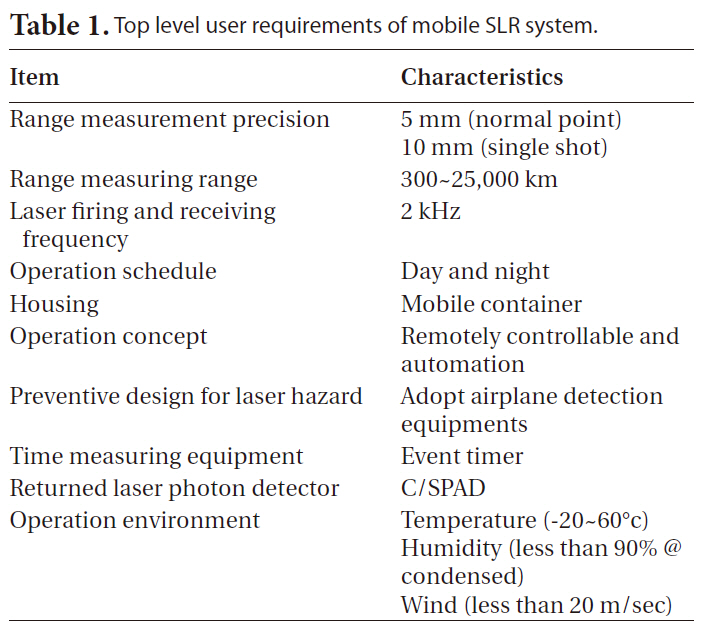
This mobile laser ranging system is being developed strictly for the purpose of geodetic satellite tracking. Due to the design restriction for the compact form factor, we decided to have 40 centimeter diameter receiving telescope. The 10 centimeter Galileo type refractor was chosen for the laser transmitting telescope. With pre?decided specifications of the mobile SLR system, major user requirement and some of specification were defined. The user requirements are shown in Table 1.
We proposed to achieve the range measurement precision up to 5 mm with normal point at the Laser Geodynamics Satellite (LAGEOS) satellite altitude. Most advanced SLR station frequently acquires same or better level of precision with their final products. In our case, it should be difficult to achieve the target precision at the first light. However, we plan to reach designed precision in normal operation with multi-step improvements.
The target observational range is from 300 km to 25,000 km as shown in Table 1. This range overlaps the operational orbit altitudes of low Earth orbit satellites and satellites of the global navigational satellite systems. Main target satellite should be equipped with a set of laser retro reflector. Due to the size of the receiving telescope, tacking of geosynchronous orbit satellite can be difficult.
Kirshner (2004) proved the improvement of measurement precision and the effectiveness of increased observation time and frequency with kilo Hertz system. The Korea’s first domestically built mobile SLR system is designed in kilo Hertz system base. With this kilo Hertz system and assist of narrow band filter, this mobile SLR system can be operated in daylight time as well as in the night time. This mobile SLR system will be contained in a closed container with necessary additional equipments for mobility. This container can be shipped to the remote site all over the country or even abroad. The operating of the mobile SLR system should have the capability of remote operation and automation in several procedures like observation scheduling, data reduction and handling, system status reporting, airplane detection, satellite tracking, emergency shut-down, ground calibration, etc.
[Table1.] Top level user requirements of mobile SLR system.

Top level user requirements of mobile SLR system.
[Table 2.] Pre defined major specification.
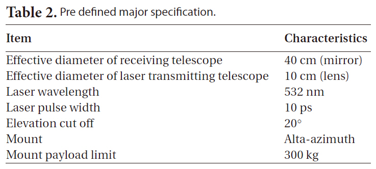
Pre defined major specification.
During the preliminary planning stage, several specifications were defined from the top level user requirement and limitation of design.
In Table 2, the major specifications are presented. The sizes of the two telescopes are selected to satisfy the required light gathering power, the payload weight budget, and the size of mount to fit the container. The laser wavelength is decided on the basis of consistency with the International SLR community. The arrangement of mount and telescope inside of the container creates the visibility limitation. The proper elevation cut-off angle is set to 20 degree due to the obstruction. The alta-azimuth type tracking mount is selected for fast slew and tracking rate.
3. DESIGN CONCEPT OF MOBILE SLR SYSTEM
The top priority of the design concept should be ‘mobility.’ Most of the constraints can be originated from this condition. Each budget of volume, power, mass and electricity must be determined based on this condition. The modular design concept will be adopted to the design of the sub-systems. Eventually, KASI will develop two SLR systems with identical functional configuration except the quantitative characteristics of the equipments and
the observation targets. Therefore many part of the modular design can be applied to each SLR system without modification. For the normal operation, automation of routine processes will be pursued to reduce the manual labor and the human induced errors. The remote access, control and operation of the operation system must be implemented.
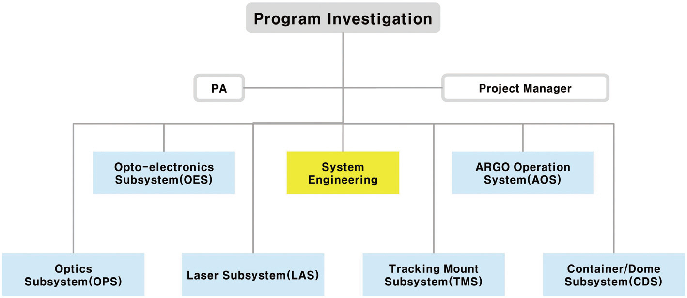
The ARGO-M (mobile) system is being developed with the collaborative system as shown in Fig. 1. Four internal groups of the KASI and 5 groups from other institute are working together for multi-level of sub-systems
The sub-systems of ARGO system consist of 1) ARGO operating systems, 2) optical sub-system, 3) opto-electronics sub-system, 4) tracking mount sub-system, 5) laser sub-system, and 6) container/dome sub-system.
It was categorized for the convenience of work grouping. The budget and personnel are arranged to each development team after the allocation policy has been discussed.
The top level functionalities of each sub-system are presented in Table 3.
[Table 3.] The functionalities of sub-systems.
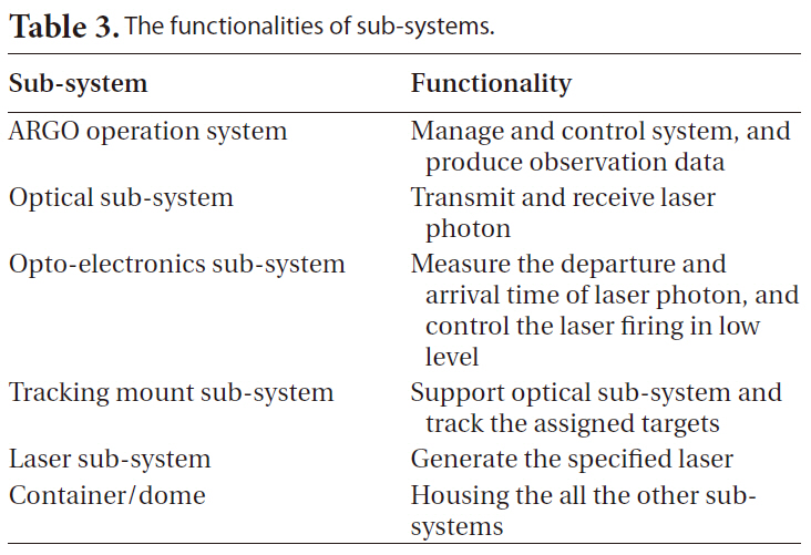
The functionalities of sub-systems.
4. sub-SYSTEMS OF MOBILE SLR SYSTEM
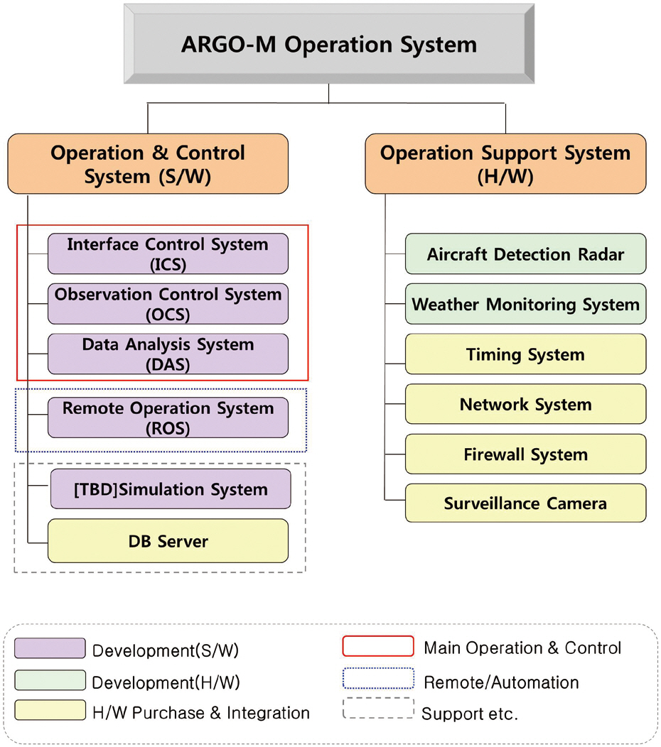
ARGO operation system (AOS) is a system that can monitor the status of other sub-systems and the envi-
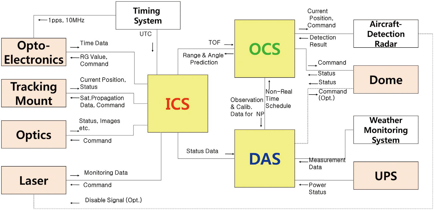
ronmental factor for the observation, make the decision for observation, and produce the products. AOS consists of “Operation and control part” and “Operation support part” as shown in Fig. 2. The “Operation and control part” manages the operation of the entire system. The “Operation support part” includes the equipments for laser observation. Brief interface connectivity with other sub-systems is drawn in Fig. 3. Seo & Rew (2009) and Rew & Seo (2009) are referenced in this section.
4.1.1 Operation and control part
The key components of “Operation and control part” are interface control system (ICS), observation control system (OCS), and data analysis system (DAS).
4.1.1.1 Interface control system
ICS is sending the command from an observer to a specific sub-system and transferring the data and status from sub-systems to an observer or to a specific sub-system. ICS is based on a real time operating system due to the time sensitive operations. The main functionalities of ICS are the controls of a tracking mount, a star camera and the laser system, and the status check of time synchronization and other systems.
4.1.1.2 Operation control system
OCS has two major functions of real-time prediction and scheduling. Also OCS can accept observer’s interruption on the existing schedule. In addition, OCS performs star and ground calibration, and dome control for protecting equipments against bad weather.
4.1.1.3 Data analysis system
DAS produces normal points as final products after the observation of one arc of target satellite and sends regularly produced normal points to international laser ranging services. DAS is acquisitioning the weather data from weather monitoring system as well as status data from other systems. DAS can also decide to close the dome directly on the basis of continuously collected weather information as OCS does so.
4.1.1.4 Remote operation system
Remote operation system (ROS) is controlling and monitoring observation processes in real-time. It has a server-client structure. DAS is a server of ROS in ARGO-M. Then ROS can display and verify the observation data from the ROS server (DAS).
4.1.2 Operation support part
Radar system, weather monitoring system, timing system, and surveillance camera are priority members of operation support part.
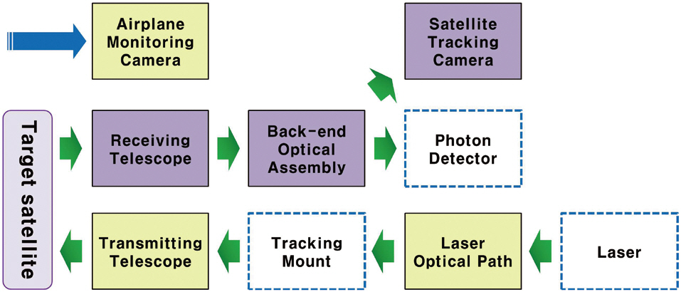
Optical sub-system (OPS) has three major functions; “laser transmitting,” “returned laser photon receiving,” and “telescope back-end optical path.” The components of OPS are entire laser optical path, transmitting/receiving optical assembly, back-end optical assembly, satellite tracking cameras, and airplane monitoring camera as shown in Fig. 4. Na et al. (2009) and Kim et al. (2009) are referenced in this section.
4.2.1 Transmitting telescope
Transmitting telescope illuminates the target satellite with a laser light emitted from the laser generator. Galilean type reflector is decided to use as the transmitting
telescope. It has tip/tilt mirror components to control the transmitting direction and an optical control component to control the dispersion angle.
4.2.2 Receiving telescope
Receiving telescope receives the return laser signal from a target satellite and relays it to the back-end optical bench. The design of receiving telescope is based on Ritchey-Chretien type reflecting telescope. A detachable window is added to prevent dust inside the optical tube assembly. The diameter of this primary mirror is decided as 40 cm.
4.2.3 Back-end optical assembly
Back-end optical assembly relays the received laser photons to satellite tracking camera and compensated single photon avalanche diode (C-SPAD) and minimizes background light noises. Back-end optical assembly has sun shutter, diaphragm, beam separator, neutral density filter, and narrow band filter.
4.2.4 Laser optical path
Laser optical path relays the laser light from the laser generator to transmitting telescope. The mirror on the laser optical path has multi-layer dielectric coating to resist laser power. The mounts of the laser mirrors have two-axis align control.
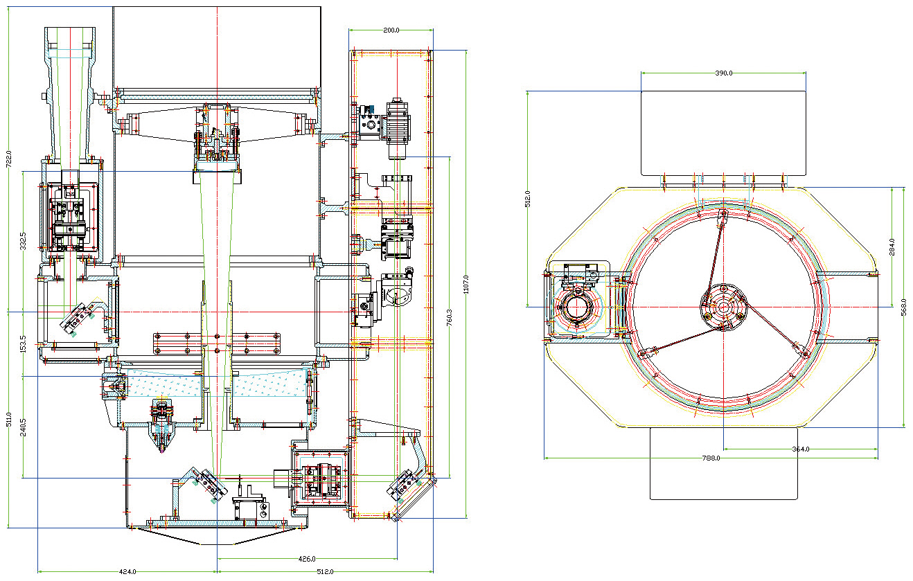
4.2.5 Optical tube assembly
Optical tube assembly (OTA) is housing the receiving telescope and the transmitting telescope as shown in Fig. 5. To ensure the quality of observation data, the rigidity of OTA should be secured properly. The components of OTA are supporting the optical parts and other components with minimum distortion. As ARGO-M is movable, compressed springs are applied to the side of primary mirror for protection. OTA consists of tube (spider and secondary mirror cell included) for primary and secondary mirrors, supporting part for back-end optical assembly, and a center piece for joint with the tracking mount.
4.2.6 Satellite tracking cameras/airplane monitoring camera
Satellite tracking cameras can track a target satellite in the night and day. A low light image sensor is used for the night time satellite tracking camera. An airplane monitoring camera will be used to monitor any aerial vehicle in the direction of laser transmitted to prevent harmful effect of laser on the pilot.
4.3 Opto-Electronics Sub-System
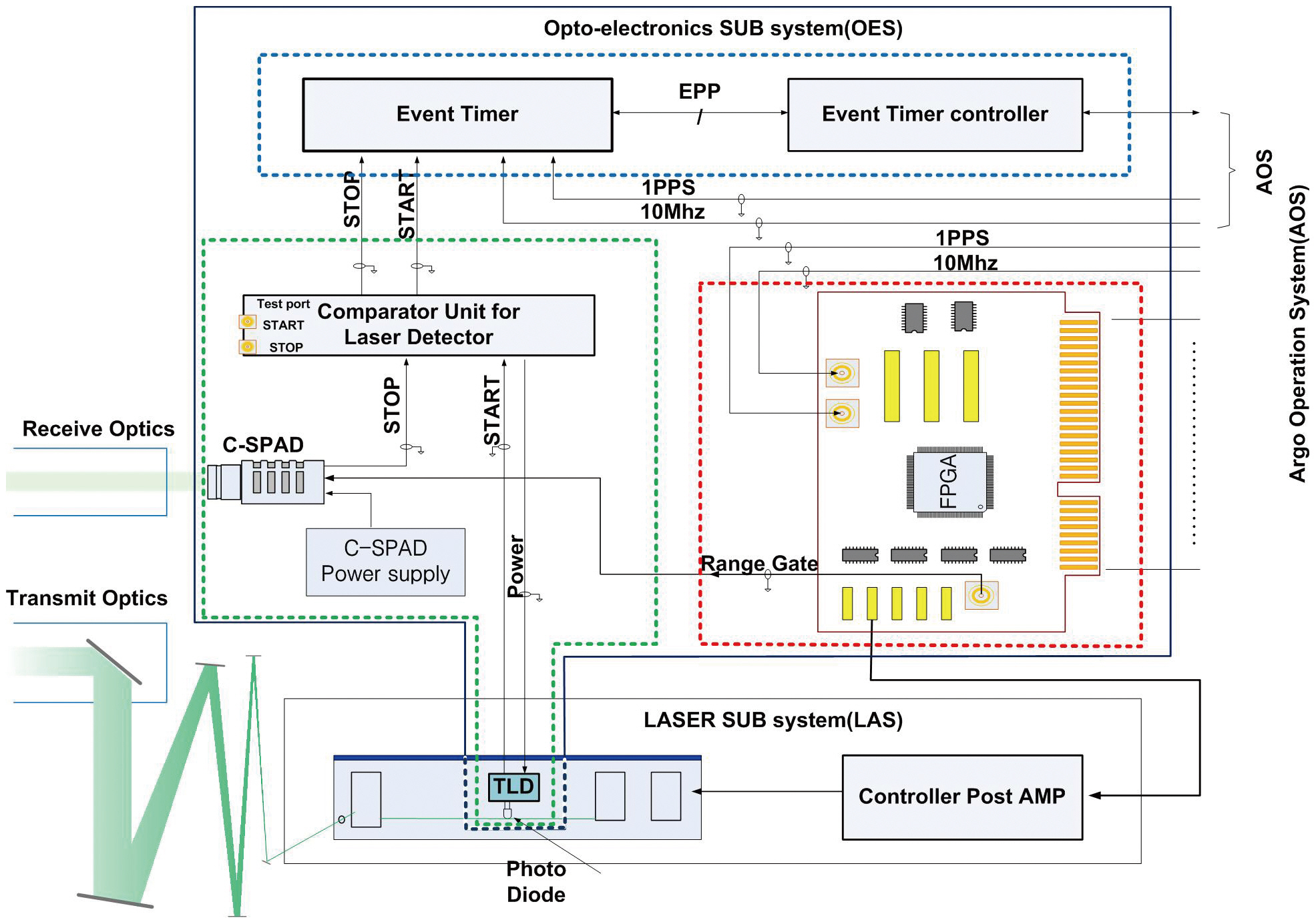
Opto-electronics sub-system (OES) measures the departure and arrival times of laser pulses to observe the range to the target satellite and controls its components. OES consists of transmitting /receiving photon detectors, event timer system, and an opto-electronics controller (field programmable gate array, FPGA) as shown in Fig. 6. We adopted kilo Hertz SLR system in Graz, Austria, for the conceptual design of OES. Bang (2009) and Bang et al. (2009) are referenced in this section.
4.3.1 Transmitting/receiving photon detectors
Transmitting/receiving photon detectors are transmitted laser detector (TLD), C-SPAD respectively. A comparator compensates the phase differences in transmitting/receiving signals of TLD and C-SPAD. After TLD and C-SPAD detect the laser photon, these generate electrical signal and send it to the comparator. Then, the comparator transfers detected signal from C-SPAD to the event timer and the opto-electronics controller.
4.3.2 Event timer system
Event timer system measures the exact time of the detection of a photon by transmitting/ receiving photon detectors and transfer it to AOS. Event timer uses global positioning system (GPS) time synchronized time scale for reference. Event timer system consists of the event timer and event timer controller. The event timer measures the time with the frequency standard from the GPS. The event timer controller compensates internal clock errors and monitors the operation status of the internal clock to maintain the precision of time information.
4.3.3 Opto-electronics controller
Opto-electronics controller generates the range gate signal for C-SPAD and laser firing signal on the basis of the standard frequency (1 pps/10 MHz) from the GPS receiver. Opto-electronics controller consists of a timing controller, a range gate generator, and a laser firing shift controller. The timing controller defines reference time from the GPS signal. The range gate generator generates range gate signal with the high precision by comparing the range gate information computed in AOS and real-time timer information of the timing controller. The laser firing controller prevents the degradation of precision from the overlapped transmitting and receiving laser by shifting laser firing frequencies with predicted arrival time of previously transmitted laser.
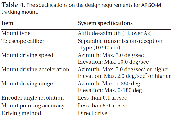
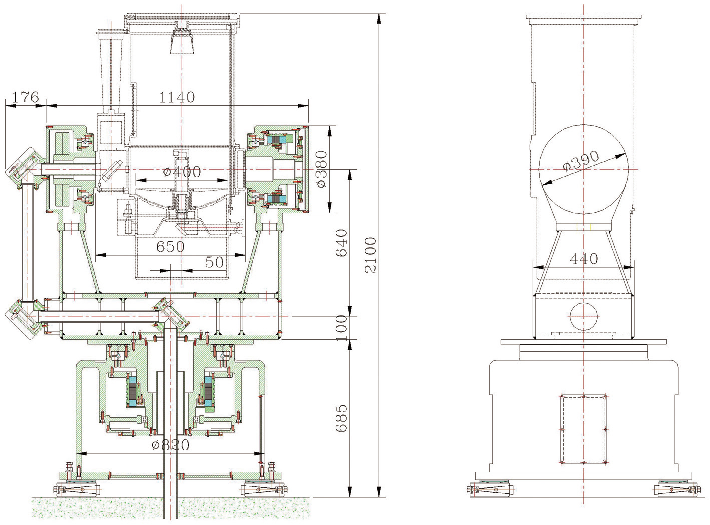
We chose a two-axis simultaneous operating Alta-Azimuth type mount for tracking and positioning of optical tube assembly. The design of tracking mount sub-system (TMS) is selected to satisfy the requirement of pointing accuracy considering payload, total weight, speed, acceleration, and external disturbance. The main objectives of the design are the assurance of structural rigidity for the stability of mount and reduction of weight. The design requirements of TMS are presented in Table 4.
The conceptual design of TMS is shown in Fig. 7. TMS consists of a mount base and frame, control system, and an interface. Son (2009b, d) is referenced in this section.
4.4.1 Mount base and frame
The precise tracking and ranging of a satellite needs literally rigid foundation; mount base and frame. It has to support optical path and optical system with solid stability for precise and fast tracking. The design of mount base and frame for ARGO-M is based on the SLR system in Graz, Austria.
4.4.2 Drive control system
Drive control system makes optical system point to target and track it with required precision. It consists of mount driving motor, motor driver, position encoder, and servo controller (Park et al. 2010).
Laser sub-system generates the green laser with about ten picosecond width pulse to illuminate laser retro reflector on a satellite. To acquire an observation data with required quality, the precision control should be applied to this system. As shown Fig. 8, Laser sub-system consists
[Table 4.] The specifications on the design requirements for ARGO-M tracking mount.

The specifications on the design requirements for ARGO-M tracking mount.
of four components; laser generator, control component, chiller, and power supply. The laser generator should be functional in extreme long term operation without power degradation and jitter in pulse width. Kim (2009a, b) is referenced in this section.
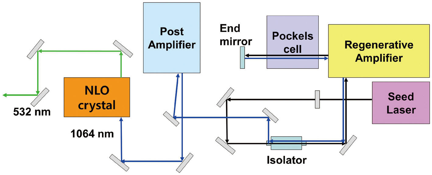
4.5.1 Laser generator
Laser generator is a device to transmit and control laser light. It consists of five components; a seed laser generator creating pulsed laser light with 1,064 nm wavelength,amplifiers, isolators, a Pockels cell, and a non-linear optical crystal. ARGO-M will use laser light with 532 nm wavelength, 10 ps pulse width, and 2 kHz repeat rate.
4.5.2 Laser generator chiller
The laser generator chiller will be used in cooling seed laser generator, regenerative amplifier, post amplifier, and post amplifier controller inside of laser generator effectively. It is necessary to remove the heat for stable operating of ARGO-M laser generator.
4.5.3 Laser controller
Laser controller has operational capabilities of checking-up on/off and operation status on-site as well as on-line and controlling major setup parameters of laser system.
4.5.4 Laser power supply
Laser power supply is providing enough specific electrical power to laser components for normal operation. An additional power supply like uninterrupted power supply can be equipped to prevent blackout and brownout.
Container/dome sub-system provides necessary space for all the other sub-systems; equipments, accessories, operational space, and telescope. It should be movable. The list of critical requirements contains environmental conditions, structure stability, thermal insulation status, and operational condition. The external electrical power should be supplied during observation. The container of ARGO-M is designed with a consideration of packing and shipping. The dome located on top of the container, as a cover for protecting the optical telescope and tracking mount, should be controlled remotely. The dome system has four main components; main frame, motor driving system, emergency stop, and safety instrumentations. Son (2009a, c) is referenced in this section.
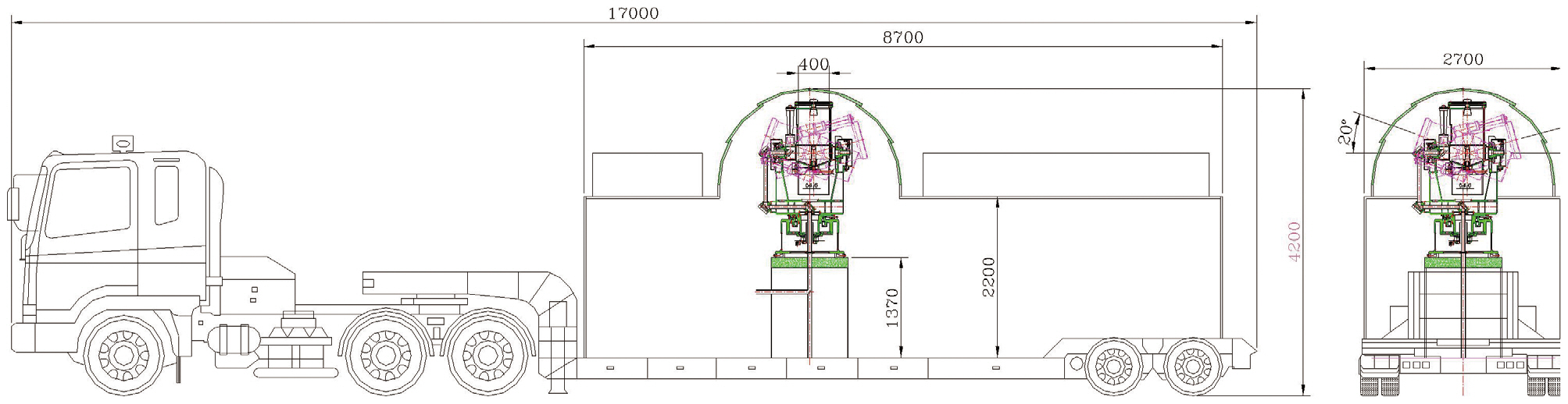
4.6.1 The design of ARGO-M container
The draft of the container specification for ARGO-M and its operation scenario is currently under review. The final specific design will be decided before the critical design review meeting. A container design with low profile trailer is suggested as in Fig. 9.
4.6.2 The design of ARGO-M dome
The design of dome should have a clear window satisfying the minimum requirement of cut-off angle. Dome should have proper space for maintenance and safety device for system and operator. Additionally, the emergency stop function should be applied to dome opera-
tion. The clam shell type dome and sliding roof top type are candidates in consideration.
The current development of Korea’s first mobile SLR system is on schedule. A successful system design review meeting was held in May 14, 2009. The brief description of the conceptual design is presented in this study. Several major and minor loop holes were defined and reviewed after the review meeting. These deficiencies will be fixed as we progress to other design reviews. The following development schedule depends definitely on the budget profile which varies yearly due to the government budget procedures. It is necessary for KASI to have close relationship with other international institutes for the development of ARGO system in schedule. The SLR technique might be considered as an old style after global navigation satellite system (GNSS) technology emerges and observation data becomes abundant. However, SLR has strong tie to the Fundamental and Absolute Astronomy. The completion of this project will make Korea contribute the international SLR and Space Geodesy communities. KASI can step forward to the research fields of advanced Space Geodesy in Korea.