The stereoscopic three-dimensional (3D) display provides a 3D image by inducing binocular disparity for the observers who wear special glasses. With the rapid progress in flat panel display technologies,the stereoscopic 3D display is becoming a new benefit-model of the current display industry, and several kinds of commercial stereoscopic 3D products have been released and are attracting people. Nowadays,the motion picture quality of the 3D image becomes as important as resolution or luminance since most of the commercial 3D products are 3D televisions or 3D monitors which are required to display a clear motion 3D image. In this paper, an analysis and simulation of the motion picture quality of stereoscopic 3D image is proposed, and a comparison of the motion picture performance among the current stereoscopic 3D technologies is also provided.
Three-dimensional (3D) display technologies are devised to make the observer sense 3D images in free space by simulating physiological and psychological cues of the human visual system [1]. With a long history of over a hundred years, various and continuous researches have been proposed to realize a 3D display system [2-4]. Among them, a stereoscopic 3D technology, which provides different left-eye and right-eye images to the observer who wears special glasses as shown in Fig. 1, can be designed to have free viewpoints of the 3D images by making the special glasses separate the left-eye and right-eye images.Therefore, the stereoscopic 3D display system can have a simple and inexpensive structure by minimizing the number of optical devices of the display system which are required to form the 3D viewpoints. For the above reasons, the stereoscopic 3D technology has been regarded as the most suitable one for the early 3D products. Although it has seemed that the 3D technologies have been far from practicality due to the low image quality and high prices,recently the basis for realizing a stereoscopic 3D display has been established with the rapid progress of the flat panel display (FPD) technologies such as Full-HD 240 Hz liquid crystal display (LCD) and 120 Hz plasma display panel (PDP) [5, 6]. As a result, several kinds of commercial stereoscopic 3D products have been recently released and are attracting consumers worldwide.
As the 3D display becomes popular, it is required that
the 3D display should provide improved, or at least the same, image quality as conventional two-dimensional (2D)FPDs do. Reviewing the progress in the 2D FPD industry,major criteria at the early stage are technologies such as display size, resolution, brightness, and contrast to improve the quality of static images. Motion picture quality has followed after them since most of the displayed contents are composed of moving pictures. Therefore, it can be expected that the motion picture quality of 3D display devices will also become another major criterion to measure device performance. However, since the imaging of a 3D display is different from that of conventional 2D FPDs, it is necessary to analyze the properties of 3D motion pictures and to establish a basis for optimization of 3D motion picture quality. In this paper, the motion picture quality of 3D imaging is analyzed based on the principles of binocular disparity, and acomparison of motion picture performance of existing stereoscopic 3D techniques using the simulation result is provided as well.
The motion picture performance, which means the ability to display a moving image with high spatial resolution, is one of the major issues of conventional 2D FPD and researchers have been trying to develop solutions to improve it. In particular, for the case of LCDs, the motion picture quality was inferior to the other FPD technologies and had to be improved. Since the motion picture quality is mainly degraded by motion blur, which means the reduction of spatial resolution of an image by blurring from its movement,motion blur is a major criterion for the measurement of the motion picture quality and it is required to be reduced for high motion picture quality. For that purpose, the response time of the liquid crystal (LC) has been improved for decades by adopting various overdriving technologies and developing new faster LC materials. However, it is well known that the LCD has motion blur due to the hold type driving even though the response time of the LC material is infinitely short [7]. As a result, driving technologies with higher frame rates, such as 120 Hz and 240 Hz, are developed to improve the motion picture quality by reducing the hold time of images on the LCD. Since most of the current commercial stereoscopic 3D products are use the LCD as a basis device, the analysis and simulation in our study are limited to the hold type displays.
The amount of motion blur in the LCD is related to various factors. The purpose of the analysis in this paper is to point out a difference between the motion blur of 2D FPDs and of stereoscopic 3D display devices. In this paper, the difference is found by analyzing factors that cause motion blur in LCDs for the cases of 2D FPD and of stereoscopic 3D display device. The analysis in this paper is based on two assumptions for satisfying the above purpose as follows: The response time of the LC material is assumed to be infinitely short and ignorable, and the motion blur of the stereoscopic 3D image is a result of motion blur from the movement of the left-eye and right-eye images for stereoscopy. The first assumption comes from the conditions of 2D FPD and it can also be used in analyzing the motion blur of the stereoscopic 3D image. The second assumption is about the difference between the motion picture performance of the 2D and 3D images. It means that the motion picture performance of the 3D image is related to the moving speeds of left-eye and right-eye images which are expected to have different moving speeds from that of the 3D image itself. Based on these assumptions, it is possible to analyze and simulate the motion picture quality of stereoscopic 3D display.
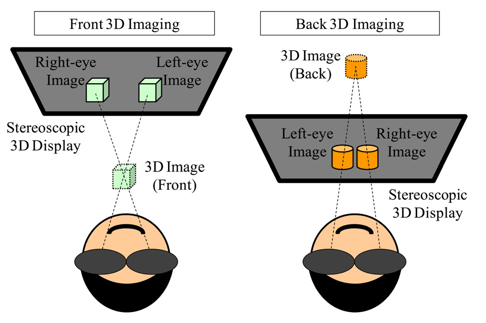
In the stereoscopic 3D imaging, there are two kinds of methods to form the 3D image by locating the left-eye and right-eye images. The front 3D imaging is a method makes the observer feel that the 3D image is formed between the stereoscopic 3D display and his/her locations as shown in Fig. 2(a). In contrast, the back 3D imaging locates the left-eye and right-eye images as shown in Fig. 2(b) so that the 3D image seems to be located behind the stereoscopic 3D display.
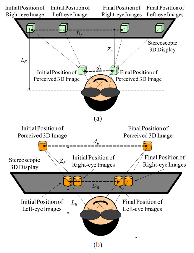
The motion of the left-eye and right-eye images are different in these two cases even if the front 3D image and back 3D image seem to move with the same speed. Figure 3 shows the parameters in two cases. In the case of front 3D imaging, the relation between the moving speeds of the perceived front 3D image and the left-eye/right-eye can be described by a following equation:
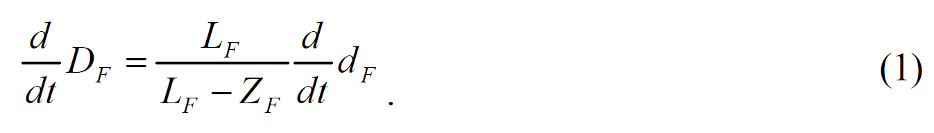
In the above equation, DF is a moving distance of left-eye/right-eye images and dF means the perceived moving distance of the 3D image.
with respect to time
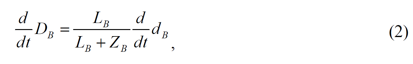
where
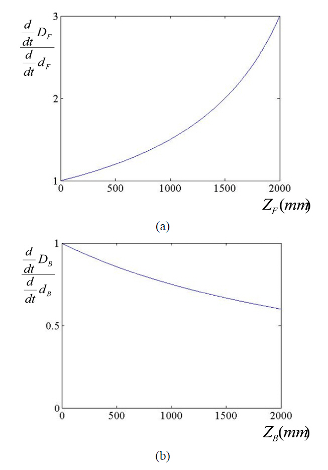
From the above equations, it is expected that the moving speed of left-eye and right-eye images will be faster in front 3D imaging and slower in back 3D imaging than the perceived speed of the 3D image. Therefore, the motion blur of front 3D imaging is larger than for the back 3D imaging if the 3D images in the two cases seem to move with the same speed. Since the depth (
increased with the depth
III. SIMULATION RESULTS AND COMPARISON
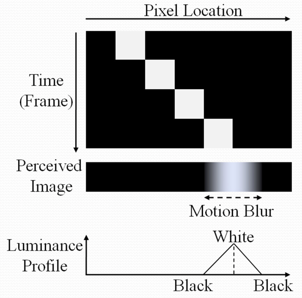
The motion blur induced by the movement of the 3D image and the property of hold type driving can be simulated based on the first assumption, which sets the response time of the LC material short enough to be ignored. In this case, the motion blur is proportional to the product of the moving distance per frame (moving speed)and the hold time of the 3D image. For the LCD, the hold time becomes the time between the frames. With the above assumptions, movement of a single pixel with moving speed of 1 pixel per frame can be simulated as shown in Fig. 5. In Fig. 5, the vertical axis shows a flow of time with frame interval. Since the observer’s direction of view follows the movement of a single white pixel in
Fig. 5 and the eye accumulates the luminance of the white single pixel during the hold time, the result of motion blur is a form of integration of the luminance in each location during the hold time. Consequently, the luminance profile of the motion blur of a single pixel has the form of a triangle as shown in Fig. 5. The motion blur of a specific image can also be simulated by integrating the expected luminance profile of each pixel making up the sample image.
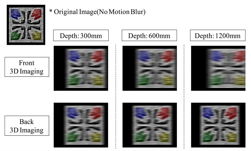
With the above technique, the motion picture quality of front 3D imaging and back 3D imaging is simulated with different 3D depths as shown in Fig. 6. In the simulation of a sample image, the hold time is set to 1/60 s (60 Hz)and the moving speed of 3D image is 8 pixels per frame for both case of front and back 3D imaging. From the results, it can be recognized that the motion blur of the front 3D imaging is increased with the 3D depth. For back 3D imaging, however, the motion blur is reduced with the 3D depth.
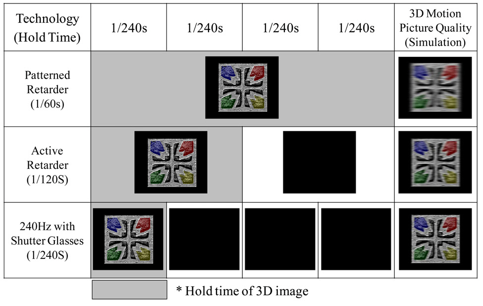
Although the basic principle of stereoscopic 3D display is to induce binocular disparity by separating the left-eye and right-eye images using special glasses, the realization of that principle can have multiple solutions. In this section,the motion picture qualities of three types of different stereoscopic 3D displays are analyzed and compared with the simulated motion picture qualities. The first technology is called a patterned retarder, which uses an additional polarization filter with a periodic pattern of orthogonal polarization in front of the display device. The patterned retarder separates the left-eye and right-eye images with
vertical line-by-line polarizer structure with orthogonal polarization [8]. As a result, the vertical resolution of the 3D image is reduced to half of the 2D resolution if the observer watches it while wearing polarization glasses.Instead, no time sequential switching of left-eye/right-eye images is needed and the conventional 60 Hz LCD can be used as basis. Therefore, in this case, the hold time of 3D images will be 1/60 s. The second one is an developing technology which is called active retarder. This method uses 120 Hz time-sequential driving to switch the left-eye and right-eye image every 1/120 s. Synchronized with the switching of images, the polarization of the entire screen is also changed by the active retarder to enable the observer to see the displayed image only by a single eye in each frame [9]. Therefore, the hold time of 3D images will be 1/120 s in active retarder technology. The last technology is a 240 Hz 3D LCD with LC shutter glasses.In this case, the left-eye image and right-eye image are switched with a speed of 240 Hz. However, to minimize the crosstalk, there are black frames between those images and the period of image switching is actually 1/120 s.Since the black frames have another effect of reducing the hold time (no display), the hold time of the 240 Hz 3D LCD with LC shutter glasses will be 1/240 s [10]. The above descriptions are summarized in Fig. 7 with the comparison of simulated motion picture quality. The simulation shows a prediction that the 240 Hz 3D LCD may have the smallest hold time for 3D images and may provide the best motion picture quality. In the real case,however, the motion picture quality may be degraded further by the response time of the LC material in the shutter glasses in 240 Hz 3D LCD and by the switching time of active retarder devices, which are not infinitely short.
The motion picture quality of stereoscopic 3D displays is related to the cue of binocular disparity and the movements of left-eye and right-eye images. For an LCD display,the motion picture quality is degraded by the motion blur which comes from the hold type driving. In this paper, the analysis and simulation of the motion blur is provided based on the above principles. The motion blur is an important issue both in 2D and 3D display systems and needs to be improved continuously. The proposed research is expected to be useful in optimizing the motion picture performance of 3D display devices. The measurement of 3D motion blur will be a subject for further research.