DH is a novel technique for recording and reconstructing the fully complex field of a wavefront [1-2]. Two processes are involved in DH: the recording process, and the hologram reconstruction process. Due to the nature of holography,three diffraction components: the dc term, object field and its conjugate, are produced in the reconstruction process.In off-axis DH, these three diffraction components are spatially separated. In contrast, in on-axis DH, the diffraction components are overlapped. However, on-axis DH has a larger field of view and space bandwidth product (SBP)than off-axis DH, features that could be very useful in some applications [3]. To solve the overlap problem of on-axis DH, various efforts have been made.
The use of multiple exposures with phase shifting is a simple solution and could eliminate both the dc term and conjugate field [4-5]. However, it requires a phase shifting mechanism during measurements. Maleki and Devaney suggested the recording of two holograms at two different distances [6]. By processing the holograms in the spatial frequency domain, they extracted the object image without the conjugate image. However, because singularities occur during the computation, they had to use an inverse filter and regularization, which requires more extensive computation.Kim and Javidi [7] also used two holograms. To reduce the dc term, the average intensity of the hologram was subtracted from the hologram. However, this method is limited to an object which has a uniform intensity distribution.Situ [8] reported a method which records four holograms from two recording planes. This method still requires a phase delay of reference beams during measurements,and it has a singularity problem.
Zhang and Tiziani [9-10] assumed a weak object wave so that the hologram signal could be approximated as an exponential function. Although this method involves simple computation and does not suffer from singularities, the assumption of the weak object wave is not always valid and favorable in terms of the signal to noise ratio. Liu and Poon [11] also assumed a weak object wave, although they retrieved the object field by two step measurements.
There are other purely iterative methods that use the Gerchberg-Saxton algorithm [12-13]. These methods, however,may strongly depend on initial guesswork and requires computations to obtain an optimized result.
Another approach using a tilted reference wave was proposed [14-16]. It has a very simple optical setup and requires no phase shifting devices. However, the isotropic phase shifting is not possible in that method. As a phaseshifting free method like the tilted reference approach, a single-exposure technique using fractional Talbot effect was reported [17]. However, the accurate fabrication and alignment of the gratings are difficult, and have a great effect on the resultant image.
Recently, pixelated optical components have been used[18-22]. These approaches can directly record phase-shifted holograms with specially designed components. However,they are difficult to fabricate and align. As a related work,Nomura [23] suggested a method using a random-phase reference wave. This method requires only ordinary imaging devices. However, they assumedthe same object and reference intensity on any neighboring four pixels.
In this paper, a new two step on-axis DH is proposed.Unlike the above mentioned methods, it does not require any phase shifting during the recording process, weak object wave assumption, and any other complicated optical components. The proposed method also provides a simple reconstruction algorithm and system setup.
A dual-channel Mach-Zehnder interferometer was employed to verify our method. The matched filter algorithm [24]was also employed to align two CCDs. Simulation and experiment results are presented as a demonstration.
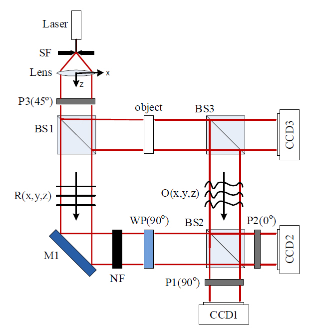
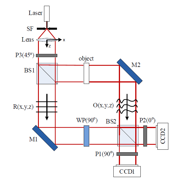
FIG. 1. is the schematic diagram of the experimental setup. The light source is a single-mode laser with 635 nm wavelength. Laser light is collimated by a spatial filter and lens, and then passes through a linear polarizer (P3) whose polarization direction is 450 with respect to the x-axis.This beam is then divided by a beam splitter (BS1) into two paths, one of which illuminates the transparent object,and the other, which passes through a quarter-wave plate,acts as the reference beam. The quarter-wave plate has the fast-axis along the y-axis. Therefore,
Generally, in on-axis DH, the hologram can be represented as follows,
where, x, y are the rectangular coordinates of the recording plane,
where, H (x, y, 0), H (x, y,
where,
Note that the object field can be obtained by two step measurements, if we use the Mach-Zehnder interferometer as shown in the FIG. 1. First, two holograms can be obtained simultaneously, having a
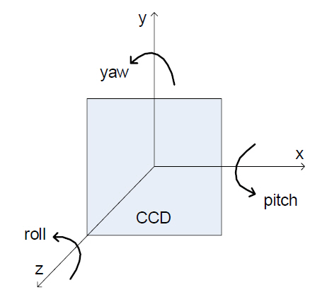
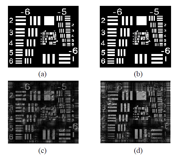
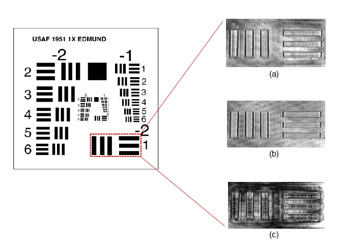
However, if the two CCDs have different positions relative to the object, the position effect should also be considered in the two hologram approach. For example, a CCD can have position information relative to the object,which are x, y, z, roll, pitch, and yaw, as shown in the FIG. 2. In general, the position information of two CCDs are different from each other. Therefore, a resolution target was employed as an object as shown in the FIG. 3(a) to examine the effect of position difference between two CCDs on the reconstructed image.
If the two CCDs have the same position relative to the object, the two holograms obtained using FIG. 1 have a difference of
In the previous paper [24], we proposed an alignment method between two CCDs using a matched filter algorithm.To put it simply, the algorithm is a kind of correlation method, which compares intensities of two CCDs. When two CCDs have the same position for an object, their intensity patterns may be very similar. Therefore,the correlation between the intensities is almost one.On the other hand, when the two CCDs have different positions, the correlation between the intensities may be a value lower than one. Therefore, in the process of making the correlation approach one, the two CCDs should have the same position for an object. For detailed descriptions about matched filter algorithm, refer to the previous paper.
FIG. 4 (a) is the reconstructed object intensity obtained by the proposed dual-channel on-axis DH. A part of USAF resolution target (38-257, Edmund) was employed as an object as shown in the FIG. 4. FIG. 4(b) is reconstructed by the conventional phase shifting method which has only one CCD. Therefore, there are not any noises caused by the position difference between detectors. FIG. 4(c) is obtained by one-channel on-axis DH without any phase shifting process. As you can see, the conjugate component of the object degrades the reconstructed image.
As shown in the FIG. 4, the proposed dual-channel on-axis DH method provides almost the same quality result compared to the conventional phase shifting scheme.Therefore, we can retrieve the object field much faster than by conventional approaches, if the position difference between two CCDs is eliminated. The proposed method consists of two processes: measurement of two phaseshifted holograms and the object intensity. In addition,there are not any limitations in our method.
Furthermore, single-exposure on-axis DH can be realized in practice based on our scheme. To realize single-exposure on-axis DH, we should use one more channel as shown in the FIG. 5. FIG. 5 is almost identical to FIG. 1, except the added detector, CCD3. CCD3 measures object intensity,and CCD1 and 2 measure two phase-shifted holograms.Then, using Eq. (2), (3), single-exposure on-axis DH can be realized in practice without any limitations. The neutral density filter decreases the reference intensity approximately in half to match the intensity level of reference and object.
In this paper, a new two step on-axis DH was proposed.A dual-channel Mach-Zehnder interferometer was employed to implement the scheme. Object field was retrieved in two step measurements. We eliminated position differences between two CCDs using matched filter algorithm, and then provided a reconstruction image which was of almost the same quality as the result from the conventional phase-shifting method. In addition, there are not any limitations in our method. Furthermore, if we use one more channel, single-exposure on-axis DH can be realized in a practical way. We believe that our scheme can be widely applied to real-time applications like monitoring dynamics of biological samples or particles in flows.