Optical fiber couplers, which either combine or split optical signals, have been used in modern fiber optic networks,biomedical imaging systems, and optical fiber sensor systems.In optical fiber communication systems, fiber couplers are the key components; they have low insertion loss, high return loss, and polarization independent operation at both 1310 and 1550 nm bands [1]. Attention has also been paid to sensing applications in which the output power ratios of fiber couplers were usually measured to detect pressure[2], temperature [3-4], ultrasound [5], and so on [6]. In recent years, several trials have been made to utilize the fiber couplers in fiber interferometers, especially for optical coherence tomography (OCT) [7-8]. In this application, the fiber coupler is mainly used as a power splitter, by which the input beam from a broadband light source is split into two; one is for the reference arm and the other for the sample arm of an OCT interferometer. Since the whole system is implemented by fiber-optics, a number of advantages including flexibility, miniaturization, easy alignment,and immunity to external influences can be expected.
In this paper, we review the fabrication procedure and the applications of specialty fiber couplers. Fiber couplers are fabricated largely in two ways. One is the Fused Biconical Tapered (FBT) method, in which a pair of optical fibers are twisted and elongated together while being heated by a hydrogen flame or a ceramic heater. Usually,the ceramic heater has better control in the heating temperature than the hydrogen heater has. The other method is based on side polishing, in which a fiber is mounted on a silica or quartz substrate and polished to an appropriate depth. Two polished substrates, embedding the side polished fibers, are then mated with each other [9]. The best benefit of the side polishing method is that the coupling ratio can be adjusted by aligning the mating angle. With various specialty fibers with the development of dedicated fabrication methods, specialty fiber couplers have been implemented for their special purposes in each application. B.H. Lee et al. reported the fabrication process of the fiber coupler made of photonic crystal fibers (PCFs) by using the FBT method in 2002[10]. The PCF, a specialty fiber consisting of regularly spaced air holes running along its length has many unique characteristics including single-mode operation in a wide wavelength range, manageable dispersion,and large modal field. Despite such unique characteristics of the PCF, its usage was highly restricted due to lack of reliable PCF couplers. In 2003, H. K. Kim et al. made a tunable PCF coupler by utilizing the side polishing method[9]. By adjusting the mating angle between two side-polished PCFs, almost 90 % tuning in its coupling ratio was obtained. Interestingly, the wavelength spectrum of the coupling ratio was flat with only small ripples over a 400 nm wavelength range. In 2010 J. B. Eom, et al. proposed a different scheme with the wavelength division multiplexing(WDM) fiber coupler fabricated by the FBT method with hole-assisted fiber (HAF) having a Ge-doped core[11]. By using a ceramic heater instead of the conventional hydrogen flame heater, he could control the fabrication condition very accurately. He showed that with a short elongation length the HAF coupler had WDM properties but with a long elongation length it became a high-pass filter. In 2007, L. Wang et al. utilized the double-clad optical fiber (DCF) coupler to couple only the cladding modes, not the core mode, of two single mode fibers(SMFs) for the fluorescence spectroscopy [12].
II. PHOTONIC CRYSTAL FIBER COUPLER
PCFs have been investigated because of their many unique properties. Usually, a PCF is composed of a single material such as silica unlike the conventional SMF that is composed of different materials for the core and the cladding. Light is guided in the core by the array of air holes made around a central defect acting as the core. By adjusting the structure of the air holes, interesting characteristics of the PCF can be achieved such as endlessly single mode operation [13], anomalous dispersion [14], large single-mode area [15], and high nonlinearity [16]. Most of these features of PCF are desirable in optical communication systems as is well-known. Recently, the application of the PCF has been extended to OCT systems. The high axial resolution of an OCT image is generally achieved by using a broadband light source such as white light.Therefore, in a fiber-based OCT system, in order to guide the broad spectrum of the source, it is essential to use not only broadband optical fibers but also broadband fiber couplers [17]. In that sense, the PCF and the PCF coupler are very attractive to the field of OCT.
The first PCF coupler was fabricated by the FBT method in 2002 with home-made PCFs [10]. With the PCF having only one layer of 4 large holes and having 5 layers of many small holes, the PCF couplers could be fabricated. Even though the FBT process for the SMF well-established, the FBT process for PCF was not yet attempted; thus, just showing the coupler property itself with PCF was a big achievement at that time. The main problem of the PCF coupler is that the air holes of the PCF are easily collapsed during fusion processing due to high temperature. However, the conventional hydrogen flame heater is not good for delicate control of temperature and does not give a uniform temperature distribution. Therefore,a ceramic heater has been tried. In 2009, the PCF coupler fabricated with the ceramic heater was reported. It showed much better temperature control ability over the conventional heater and allowed a reliable PCF coupler [18].
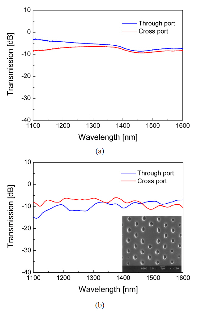
The side-polishing method for the PCF coupler was tried in 2004 [9]. It showed the excess loss of 3~6 dB. In 2007, as small as 2 dB of excess loss was obtained by H.S. Jang et al. with the PCF coupler [19]. However, this side-polishing technique is much more complex than the FBT method to fabricate the PCF coupler, because the air holes of the PCF could be very easily contaminated by the polishing powder during the polishing process. To reduce those undesirable losses and simplify the fabrication process,in 2009, the PCF-splitter was proposed based on a planar lightwave circuit (PLC) [18]. A 2×2 PCF PLC splitter,which splits optical power between two PCF channels, has been made by introducing PCF-to-PLC connections. PCF array blocks were lithographically fabricated to have the PLC splitter and fiber V grooves to firmly hold PCFs. The proposed splitter showed a rather flat splitting ratio over a wide wavelength range from 1250 nm to 1750 nm as shown in Fig. 1. With the implemented splitter, we obtained a low excess loss of 1.6 ~ 4 dB, a low polarizationdependent loss of 0.1 dB, and a high return loss of 52 dB.
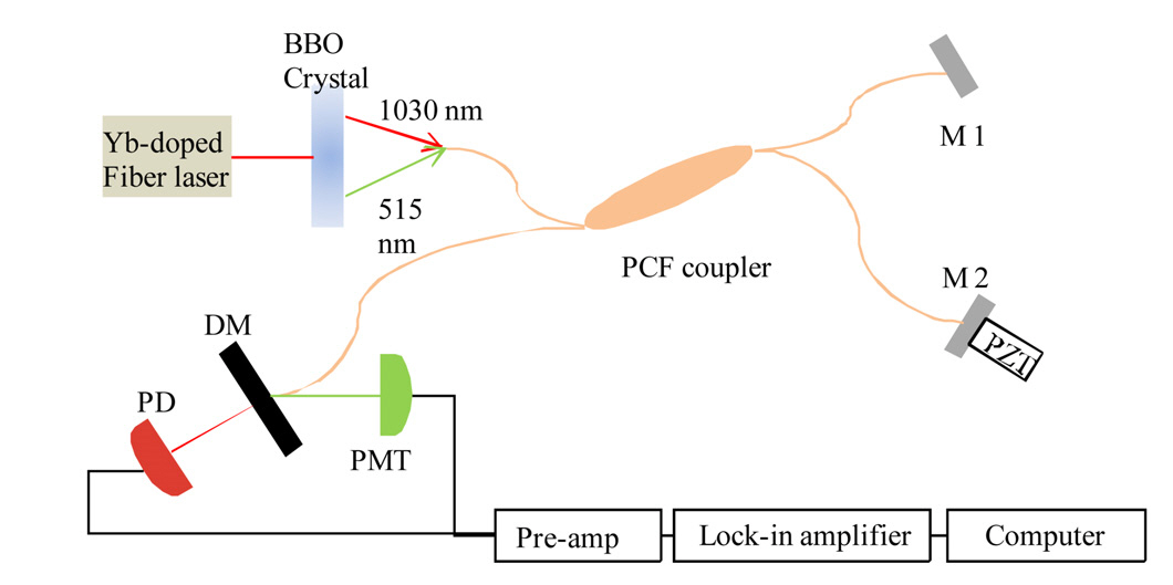
OCT is a real time optical imaging modality that produces high-resolution cross-sectional images of the internal micro-structures of biological tissues. The axial resolution of an OCT system is well-known as inversely proportional to the spectral bandwidth of the light source.However, to get a high axial resolution, using a broadband light source and using broadband waveguides and optics are equally important. For a fiber-based OCT system,therefore, the PCF and the PCF coupler are very attractive owing to their broad spectral bandwidth. In 2005, Ryu et al. successfully got the image of the cornea of a rat eye by using the PCF coupler [20]. Owing to the wide bandwidth of the PCF coupler, an axial resolution of 3 ㎛ was obtained from a white-light source with the fiber-based system. Also, recently, the interest in the second harmonic(SH) OCT has been increased due to its ability to enhance the image contrast and identify asymmetrically structured biological materials. However, to implement a fiber-based SH-OCT system, two couplers covering the source wavelength(1030 nm) and the second harmonic wavelength(515 nm) are needed. Therefore, by using the PCF coupler,we need to cover the whole wavelength span (515-1030 nm) at once. The feasibility of using the PCF coupler for the SH-OCT was successfully tested with the setup in Fig.2. [21]
III. DOUBLE CLAD FIBER COUPLER
DCF, generally having two concentric cladding layers around a single central core, was originally developed for high-power fiber lasers [22] and used for fiber gratings,
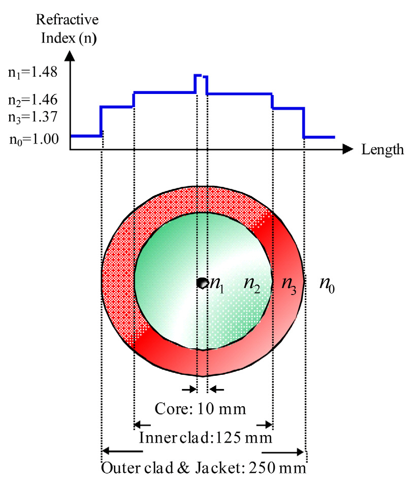
especially long period fiber grating (LPG) [23]. One of the cladding layers of the DCF, the inner one, acts as a multimode waveguide; thereby allowing another waveguide channel in addition to the conventional core channel. One of the simplest DCFs is a polymer-coated SMF. A preform of a conventional SMF is drawn with a conventional fiber drawing tower but the fiber is coated with a low-index polymer instead of a conventional high-index one during the drawing process. Figure 3 shows the cross-sectional schematic and the refractive index profile of the previously reported polymer-clad DCF [24-25], for which UVF PC-409 AP of Luvantix, Korea, was used as the low-index polymer. The diameters of the core, the inner cladding,and the outer cladding were 10 ㎛, 125 ㎛, and 250 ㎛,respectively, in a step index profile. Based on this design,a beam over the cut-off wavelength of ~1100 nm could be transmitted with single mode through its core and another beam could be guided with multi-mode through the large inner cladding area of the DCF. Since the sizes of the core and the inner cladding of the DCF were the same as those of a conventional SMF, the coupling loss between the DCF and the SMF was negligible.
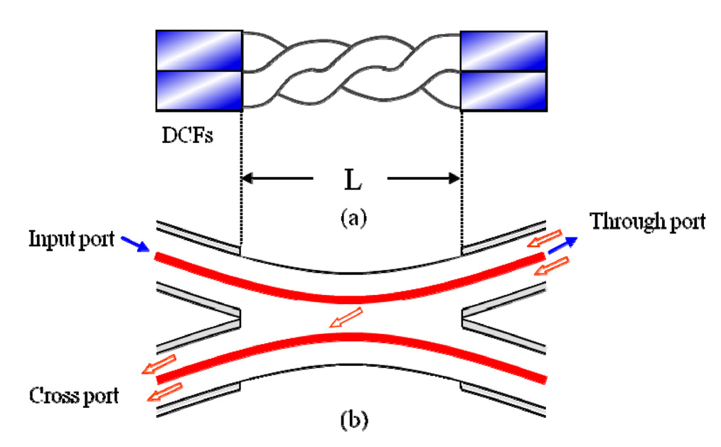
For the DCF, in addition to the conventional fiber coupler that extracts the core mode beam, a special coupler that extracts only the inner cladding mode beam is necessary when we want to use the inner cladding as the new additional waveguide channel. For the case of the polymer-clad fiber, the DCF coupler, which couples only the inner cladding modes, could be simply implemented.Simply striping out the polymer coating, the outer cladding, and physical contacting two pieces of bare DCFs allowed the implementation of DCF coupler [26-27]. To make effective contact, pair of DCFs were twisted around each other after removing the polymer jackets (the outer cladding)as shown in Fig. 4(a). Schematically, as represented in Fig. 4(b), the beam launched into the core of the input port propagates through the core of the through port, but the beam launched back into the inner cladding of the through port passes couples into the inner cladding of the cross port.
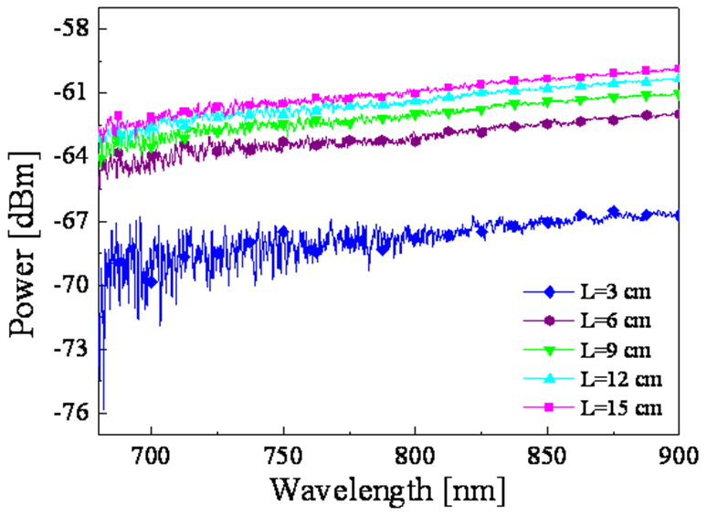
Figure 5 shows the efficiency of the coupling into the cross port, which was measured over a rather wide spectral range, 680 nm ~ 900 nm, for several contact lengths. The input beam started to couple into the cross port at L=3 cm(~6 turns); the coupled power was rapidly boosted with the coupling length up to L=6 cm (~11 turns); and then it
was slowly saturated at L=15 cm (~27 turns). Experimentally,the maximum cladding mode coupling efficiency of the DCF coupler, measured at L=16 cm (~28 turns),was measured as about 30 %. Even though the coupling length of this simple contact method is rather long, it has benefit that the coupling ratio can be simply controlled by adjusting the contact length. Of course the coupling length of the DCF coupler can be appreciably shortened by applying a kind of matching oil or gel at the contact region of the coupler. Slight fusion splicing is also possible.
Based on the dual channel ability of the DCF and the DCF coupler, a hybrid or multi-modality biomedical imaging system can be effectively implemented. Combining different modalities has been extensively tried. One of them was combining Raman spectroscopy and OCT for tissue characterization [26]. Another was the endoscope for simultaneous OCT and laser-induced fluorescence [27].However, to perform two different modalities, bulk optics and dichroic mirrors were used [26], and two different optical fibers were employed [27]. By common sense, the best combined biomedical imaging system is the one that is based on fiber optics and shares a common probe.
As was mentioned earlier, the DCF and DCF coupler enable achievement of basic requirements of the ideal multimodality biomedical imaging system. With the single mode core of the DCF, the OCT modality can be performed;and with the multi mode large area inner cladding, the laser-induced fluorescence spectroscopy (FS) modality is possible. In other words, with the core and the concentric inner cladding layer of the same piece of fiber, dual modalities can be effectively executed. Of course, with the DCF coupler, the signal in the inner cladding mode can be extracted without affecting the signal in the core mode.
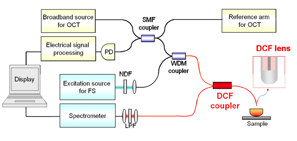
Figure 6 shows the schematic of the all-fiber combined OCT-FS system based on the proposed polymer-clad DCF coupler [28]. OCT and FS systems were combined by adopting a WDM fiber coupler and a DCF coupler. The
OCT source (SLD; 1310 nm center-wavelength, 45 nm spectral bandwidth) and the FS excitation beam (Ar-ion laser; 488 nm center-wavelength) were combined with the WDM coupler and launched together into the core mode of the DCF. The combined beams propagated to the through port of the DCF coupler and were focused by the single-body fiber lens formed at the end of the fiber [29].The back-scattered OCT signal was re-coupled into the core of the DCF, while the laser-induced weak fluorescence signal was mainly coupled into the inner cladding of the DCF by the aid of the DCF lens. For the efficient interference in the OCT modality, both in and out OCT signals should be guided with single mode waveguide, the core of the DCF in this case. However, for the FS system the induced fluorescence signal does not need to be single mode guided, therefore, the large area inner cladding of the DCF can be used as a very efficient fluorescence channel.
The back-scattered OCT signal re-entered to the OCT system through the DCF core and interfere with the reference signal. On the other hand, the FS signal collected by the same DCF lens was primarily guided through the inner cladding of the DCF, but coupled to the cross port of the DCF coupler through the inner cladding. Since the DCF coupler exclusively coupled the inner cladding modes,only the fluorescence signal was directed to the FS detector,a spectrometer in this case. To remove the residual excitation beam, a long wavelength-pass filter was used just before detection. With the implemented OCT-FS system, both the OCT signal and the fluorescence spectrum of a plant tissue were taken at the same time and exactly at the same location across the sample. Of course by scanning the common probe, the DCF lens in this case, a two-dimensional OCT image and the corresponding fluorescence spectrum map could be obtained [28].
IV. FIBER COUPLER BASED ON HOLE-ASSISTED FIBER WITH A GE-DOPED CORE
HAF that has one layer of air holes around a Ge-doped core, as well known, shows very small bending sensitivity.However, to be used in a HAF optical system, some basic fiber components for the HAF should be available also;one of them is the fiber coupler. Recently, the HAF coupler has been successfully fabricated by using the FBT method and with a ceramic heater, which had better control in the heating temperature over the conventional hydrogen flame heater [18]. In order to prevent air hole collapsing of the HAF during the fusion process, the ceramic heater temperature was intentionally lowered by a couple of hundred degrees below the one for the conventional SMF coupler [10]. In experiment, it was observed that the coupling action commenced at an elongation length of about 9 mm, which was a little bit longer than
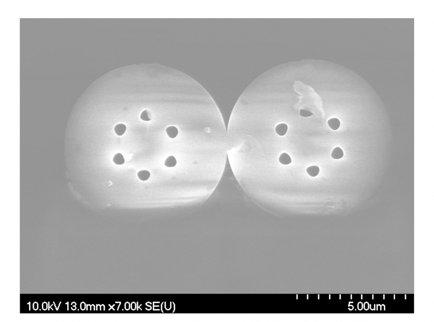
the SMF case of 7 mm [11]. Figure 7 is the SEM image of the cross section of an implemented HAF coupler,which was taken at near the very center of the fused area.The original 125 ㎛ cladding diameter was reduced down to 7.6 ㎛ and the hole sizes became as small as 0.65 ㎛.However, we can see that each fiber maintains its original air hole structure well. As the elongation length of the
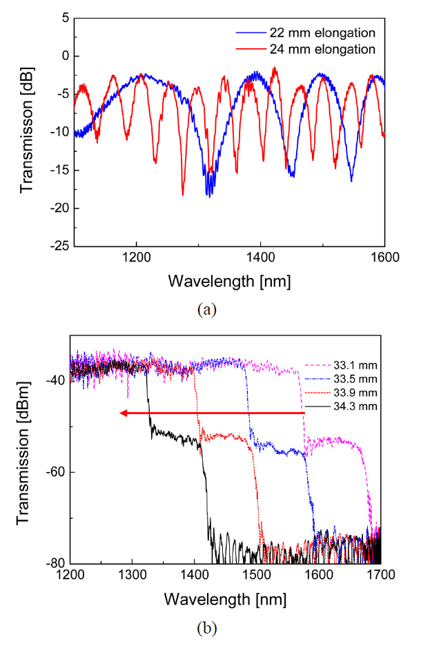
HAF coupler increased, as shown in Fig. 8, the coupling ratio spectrum varied more rapidly. At very long elongation lengths, the air holes were appreciably collapsed, and the HAF coupler did not keep the WDM characteristic anymore but became a high pass filter, as shown in Fig.8(b).
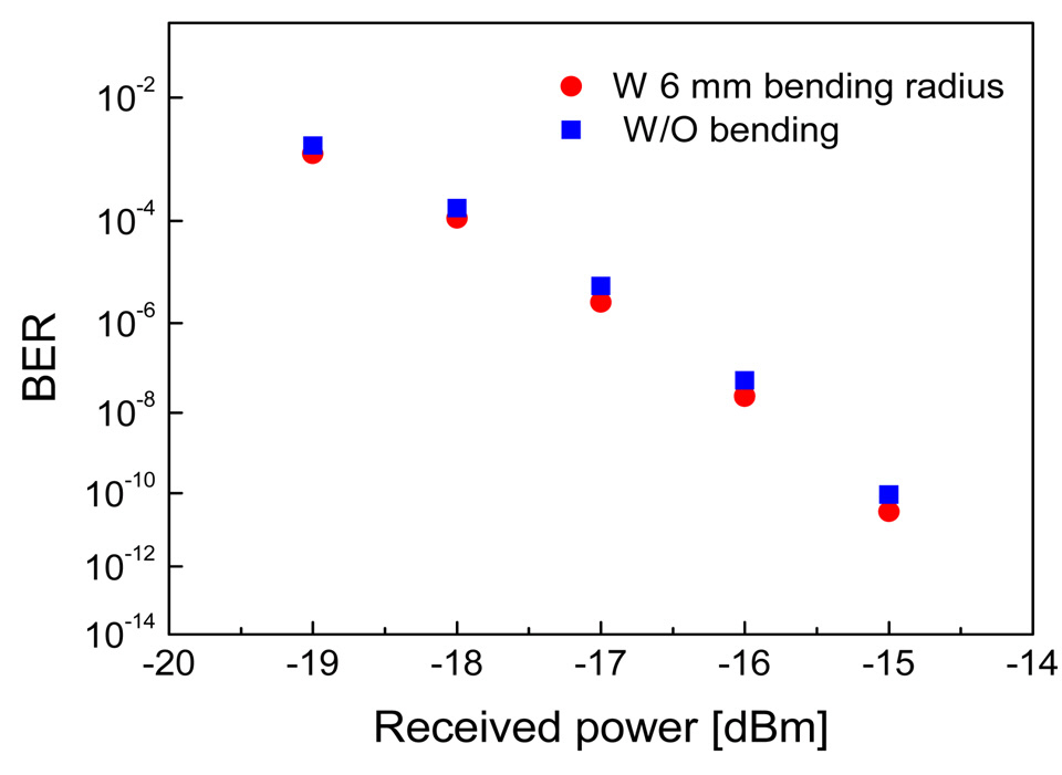
The transmission performance of HAF WDM coupler was also examined. A set of 10 Gbps optical pulses were generated at wavelengths of 1310 and 1550 nm. The two signals were transmitted through a 20 km long SMF, and then guided into the HAF WDM coupler. At both output ports of the coupler, the bit error ratio (BER) performance of HAF WDM couplers were measured with/without 6 mm bending radius at the PCF. Figure 9 presents the BER curves measured at the 1310 nm port, which shows that the HAF WDM coupler has almost no power penalty caused by the 6 mm bending radius [30]. At the 1550 nm port, the same negligible power penalty was observed also.
We have reviewed the research progress of specialty fiber couplers, which have vastly extended the applications from fiber optic communications to biomedical imaging and fiber optic sensing systems during the past few decades.The fiber couplers were fabricated largely by two methods;FBT method and side-polishing method. In the FBT method,for fusing the fibers, usually a hydrogen flame was used.However, for better temperature control and for getting more uniform temperature distribution, ceramic heaters have been adopted. With the side-polishing method, the coupling ratio of the coupler could be adjusted by simply rotating the mating angle between two side-polished fibers,which were embedded in quartz blocks. In addition to the conventional SMF, specialty fibers have been utilized also,including PCF, DCF and HAF.
SMF has limitations on the single mode bandwidth, core mode area and bending sensitivity. The single mode bandwidth limitation was solved by using the PCF having an endless single mode property. Owing to the wide bandwidth of the PCF and PCF coupler, a high resolution OCT system and a second harmonic OCT system could be implemented. By using DCF, it became possible to deliver the laser-induced fluorescence signal through the large diameter cladding of a fiber. Through the original small core of the DCF, at the same time, the fluorescence excitation laser beam and the in and out OCT beams could be delivered together. Consequently, owing to the dual channel ability of DCF and DCF coupler, a multimodal biomedical imaging system could be implemented. Finally,the problem of bending sensitivity of SMF could be solved by using HAF and HAF coupler. By precisely controlling the pulling length and the operating temperature, a WDM coupler could be fabricated with the HAF.
To utilize the unique properties of specialty fiber, we should have some associated devices. The dedicated fiber coupler is one of the essential devices. Even though many trials have been made to fabricate practical or right applicable 2×2 specialty fiber couplers, but the best fabrication condition has not yet been achieved. Efforts to improve the performance and to expand the application field of the specialty fibers and their dedicated couplers are expected.