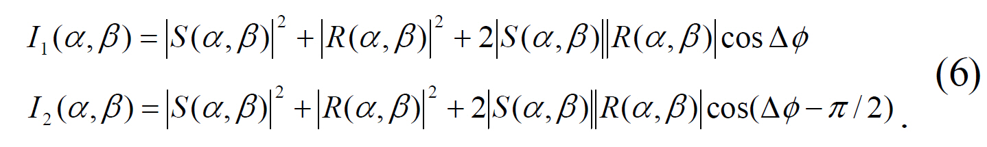
We propose a new 2-step phase-shifting digital holographic optical encryption technique and analyze tolerance error for this cipher system. 2-step phase-shifting digital holograms are acquired by moving the PZT mirror with phase step of 0 or π/2 in the reference beam path of the Mach-Zehnder type interferometer.Digital hologram with the encrypted information is Fourier transform hologram and is recorded on CCD camera with 256 gray-level quantized intensities. The decryption performance of binary bit data and image data is analyzed by considering error factors. One of the most important errors is quantization error in detecting the digital hologram intensity on CCD. The more the number of quantization error pixels and the variation of gray-level increase, the more the number of error bits increases for decryption. Computer experiments show the results to be carried out encryption and decryption with the proposed method and the graph to analyze the tolerance of the quantization error in the system.
As communication network such as the internet and the mobile net develops, there is a strong need for information security. However, because the communication network is not secure from information cracking, drains of personnel information and abuses of privacy certificates become serious problems. Recently, various kinds of optical processing have been proposed for cipher and security systems.[1-9] In each case the optical encrypted information has complex values,and thus holographic recording may be required. This requirement makes it difficult to store and transmit the encrypted information over digital networks. However, optical encryption and decryption to record and reconstruct the complex values can easily be performed using a phase-shifting digital holographic technique. The phase-shifting digital holographic technique that uses a charge-coupled device(CCD) camera for direct recording of a hologram has an advantage of real time digital information processing not using holographic recording media, and it can record the full complex information.[10-19] However, when the encrypted information is transmitted, minimizing the amount of data is important for fast data transmission. Therefore, a 2-step phase-shifting digital holographic technique is more efficient than 4-step or multi-step phase-shifting methods because the 2-step method uses less data than multi-step methods to restore or transmit the encrypted data. [15, 16, 18, 20]
In this paper, we propose a technique for optical encryption of the binary data by using 2-step phase-shifting digital holography,and we analyze tolerance error for the decryption procedure. The encrypted Fourier transform hologram is obtained by use of one random phase mask attached to an SLM (Spatial Light Modulator) with binary data in the object beam and another random phase pattern displayed on an SLM with a security key code in the reference beam of an optical setup based on Mach-Zehnder type interferometer,and a 256 gray-level quantized digital hologram is obtained by the CCD. The encrypted digital hologram can be transmitted over a digital communication network. The decryption can be carried out either digitally or optoelectronically.In section II, the encryption technique with 2-step phase-shifting digital holography and error analysis are described. In section III, computer experiments show results of the reconstructed data and the graph to analyze the quantization error. Finally, conclusions are briefly summarized in section IV.
2.1. Encryption and Decryption
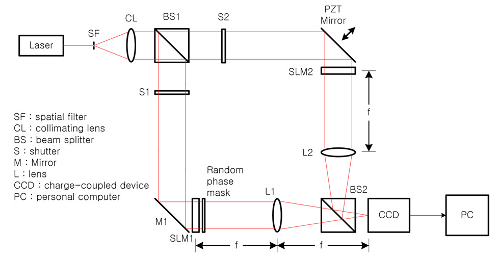
Fig. 1 shows the optical setup for encryption with phaseshifting digital holography, which is based on Mach-Zehnder type interferometer architecture. Beam splitter BS1 divides collimated light into two plane waves, the reference and the object beams. With shutter S1 open and after reflecting in a mirror M1, the object beam illuminates the phase-type SLM (SLM1) which displays the binary data to be encrypted.The output beam from SLM1 is multiplied by a random phase mask, resulting in a Fourier transform on the CCD by lens L1. The random phase mask improves the signal by widening the dynamic range of the Fourier transform in the spatial frequency domain on the CCD. With shutter S2 open, the reference beam after being reflected by the PZT mirror illuminates the phase-type SLM (SLM 2), where another random phase pattern with a security key code is displayed, and the beam is Fourier transformed on the CCD by lens L2. This concept is analogous to double-random phase encoding. [4] However, since the proposed encryption system uses phase masks at the spatial plane instead of placing the phase mask at the spatial frequency plane, it has advantages of requiring less precise alignment and simple setup.
Let
phase pattern with unit amplitude can be displayed on the phase-type SLM and is expressed as
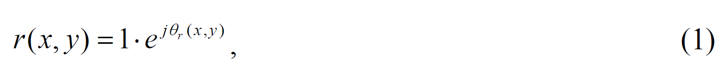
where unit amplitude is implemented optically by a plane wave in the reference beam. Fourier transform of
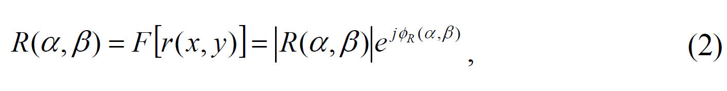
where
Let ?
Fourier transform of
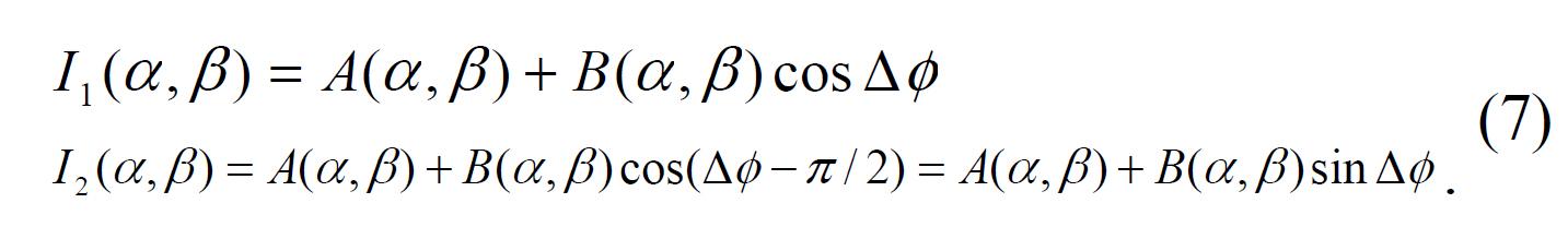
Then, the digital holographic intensity pattern recorded by the CCD camera at the spatial frequency plane is given by
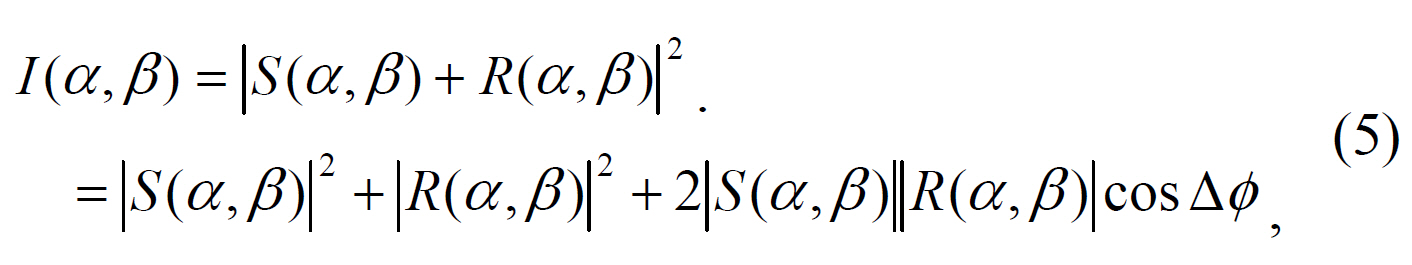
with the reference beam and the object beam given by Eqs. (2) and (4), where
These two digital holograms are encrypted data, which is stored in a computer and transmitted through the digital communication network.
With Eq.(6), Let ?
The only object beam intensity recorded on the CCD camera gives ?
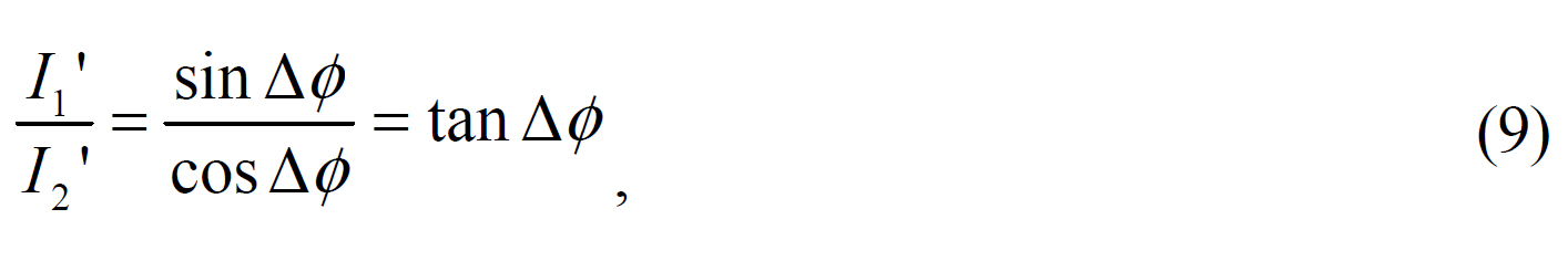
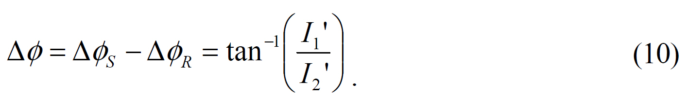
From Eq. (8), the phase difference of the object beam and the reference beam is calculated as follows.
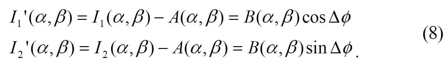
DC-term re]moval is effective for calculating the phase difference easily. Using Eq. (7) and (8), the magnitude of the AC-term is calculated as follows.
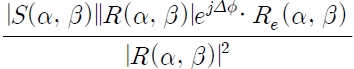
From Eqs. (10) and (11), the complex hologram with encryption information is expressed as
In order to get the complex distribution
?
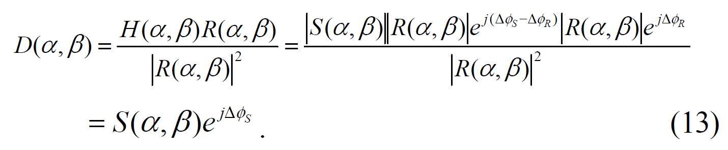
By using an inverse Fourier transformation, the data information of the object beam is reconstructed and the original binary data is decrypted after carrying out the proper threshold.

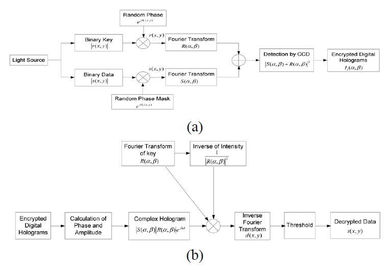
Fig. 2 shows block diagram of encryption and decryption procedures.
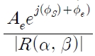
A digital hologram recorded on the CCD is quantized with 256 gray levels. So, a gray level error on CCD camera pixels can be generated due to a small intensity variation.This error is defined as quantization error, which can cause reconstructed data to have wrong bits with respect to the original data. First, the complex hologram which has the error due to gray-level variation(Δg) can be represented as
where ?S
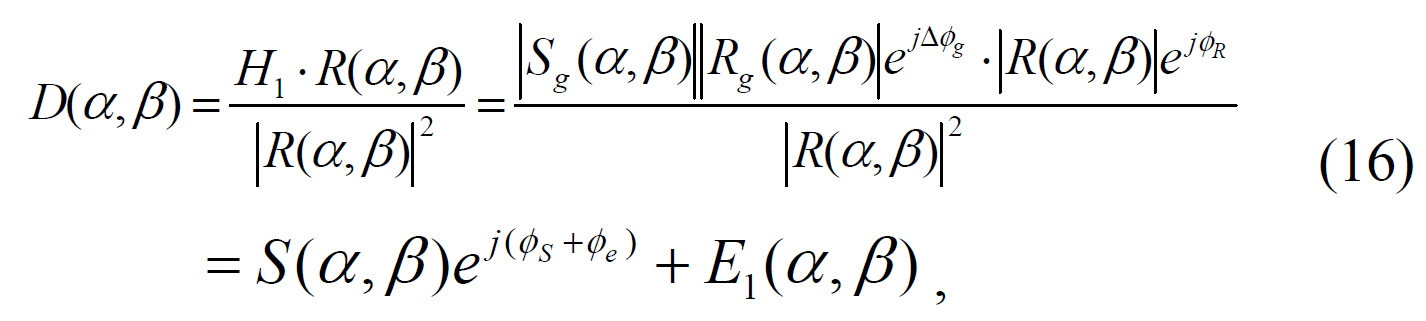
where
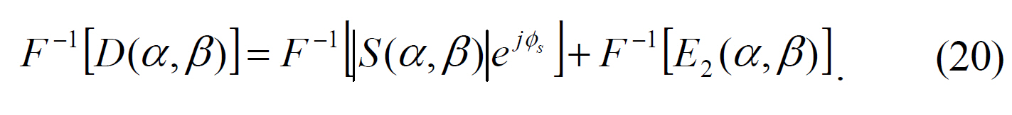
By an inverse Fourier transform of Eq. (16),the original data is decrypted as follows.

If
Next, another error is generated when the original data is decrypted even though an incorrect security key is used.Assume that
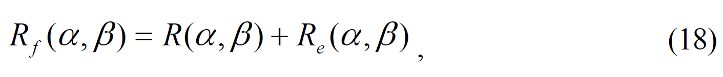
where
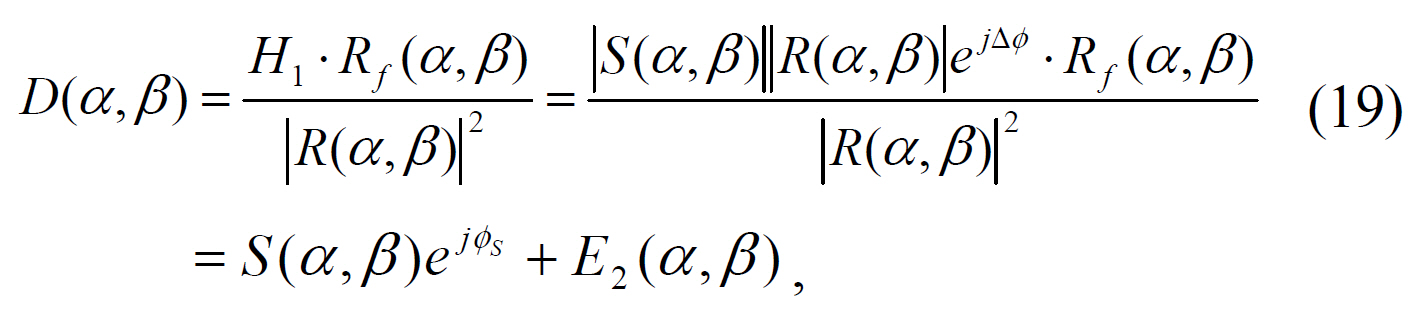
where
By an inverse Fourier transform of Eq. (19), the original data is decrypted as follows.
If
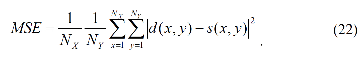
In the proposed system the number of error pixel between the original data and the decrypted data is defined as
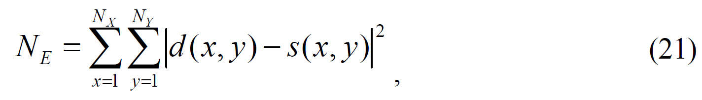
where
We show the performance of the proposed encryption method by computer simulations. The binary bit and image data of size 128×128 pixels shown in Fig. 3(a) and (b) are used as input data to be encrypted, and Fig. 3(c) shows a phase map of a random generated phase mask pattern for encryption and decryption. We use a random generated binary bit data as general input data because any analog data can be encoded into binary bit data which shows some randomness.
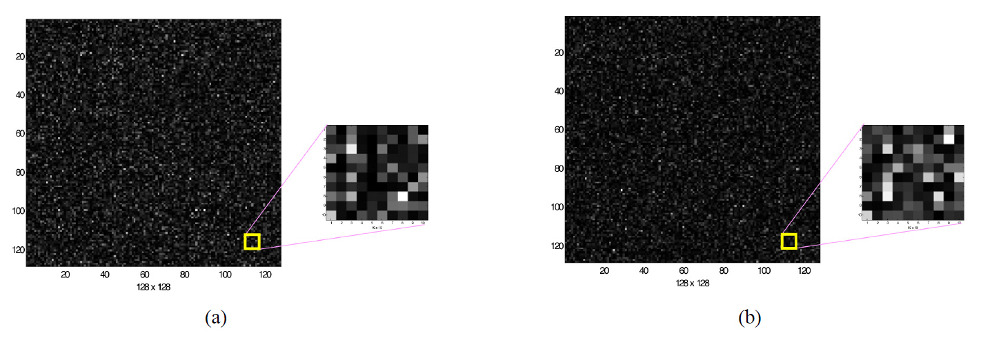
Fig. 4 shows an example of two encrypted digital holograms of the encrypted data shown in Fig. 3(a) or (b) using 2-step phase-shifting digital holography. Each hologram is
quantized with 256 gray levels. From the complex hologram calculated by the encrypted phase and amplitude and the same encrypting key, reconstruction and decryption of the encrypted data are carried out successfully.
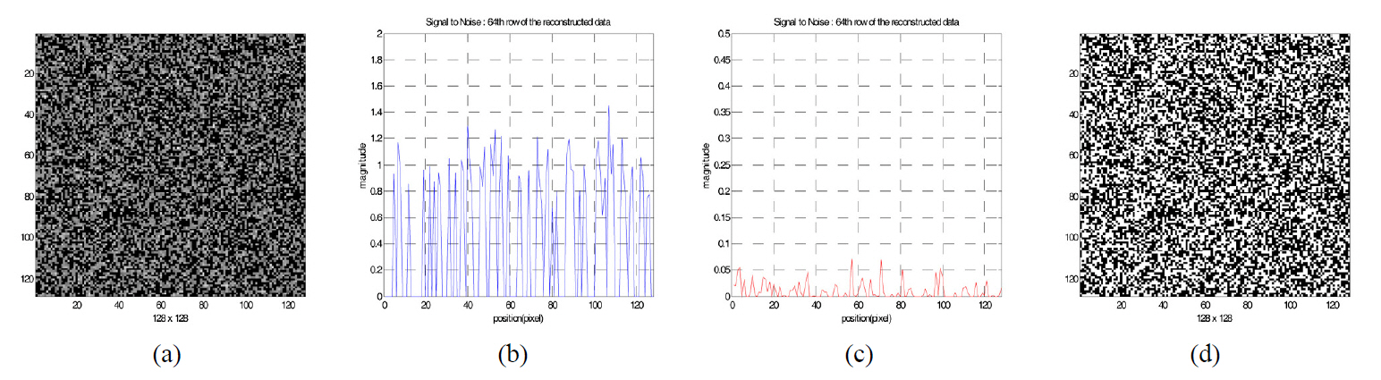
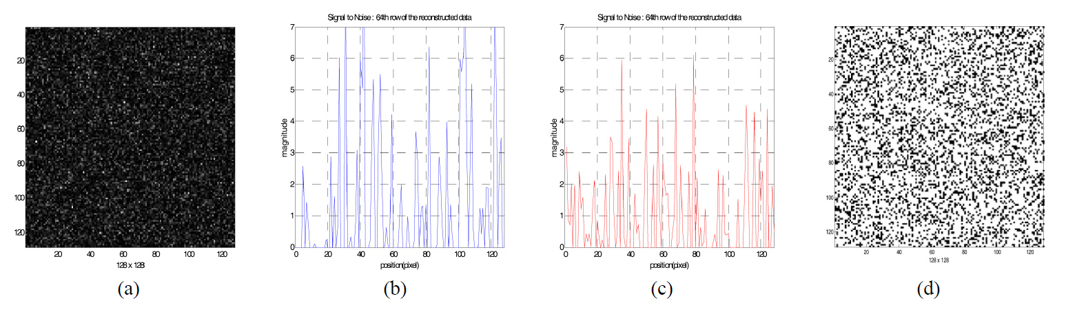
Fig. 5 shows the reconstructed binary data when the incorrect security key is used for decryption, which has a different phase pattern compared to the one used for encryption.We investigated the distribution of the pixel magnitude of the reconstructed data pattern. One of the cross sections in the reconstructed data is shown in Fig. 5(b) and (c). Since the magnitude of the noise bits (zero value in the original bit data) of some pixels are bigger than the magnitude of signal bits(one value in the original data), the threshold value cannot be defined. Therefore, the reconstructed data cannot be decrypted into the original bit data.
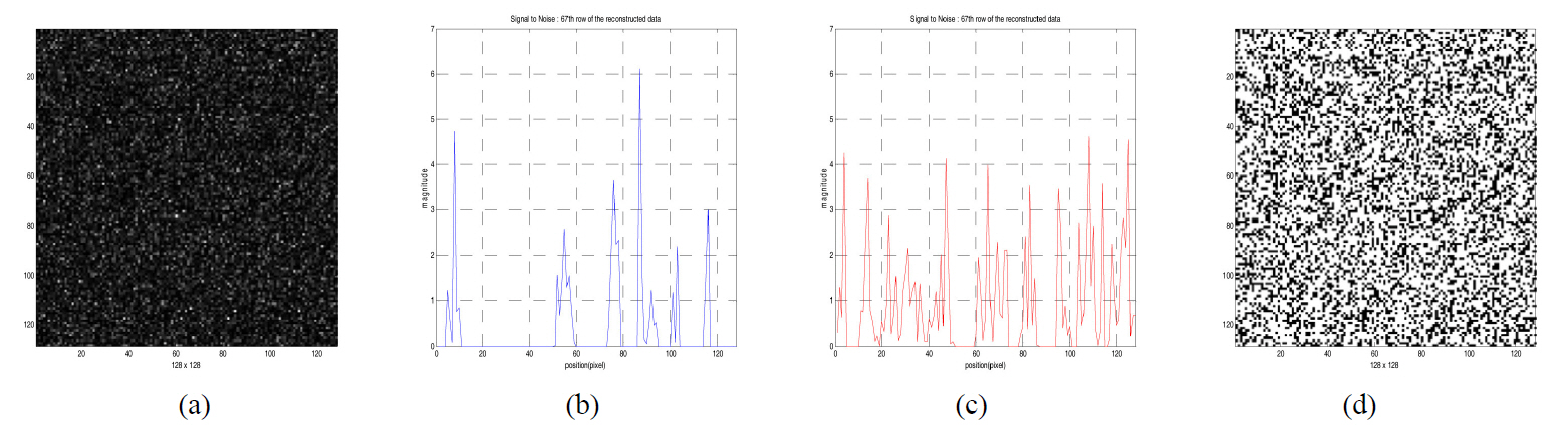
Fig. 6 shows the reconstructed data when the correct security key is used. The magnitude of signal bits is about 1 in Fig. 6(b), but the magnitude of the noise bits is below about 0.1 for the decryption in Fig. 6(c). Fig.6(d) is the decrypted binary bit data after binarization with the proper threshold value. We notice DC-term removal is essential to reconstruct the original binary data for our 2-step phase-shifting digital holography.
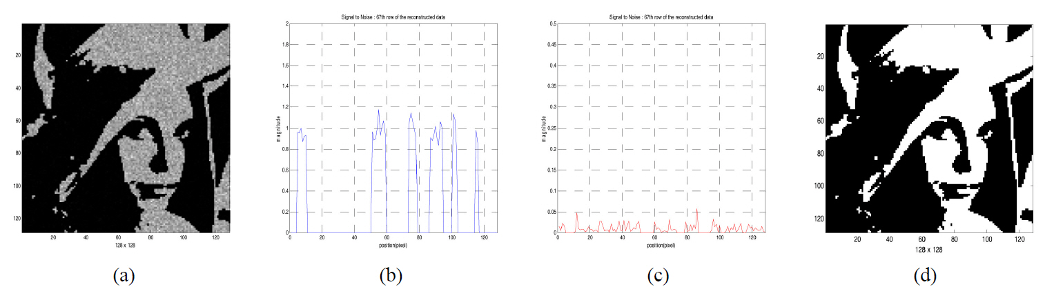
In a similar way, Fig. 7 and Fig. 8 show the results of decryption for the binary image data shown in FIG. 3 (b)when incorrect or correct security key is used, and show the reconstructed image patterns by decryption process and one of the cross sections in the reconstructed image data.
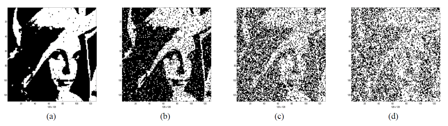
Fig. 9 shows the results of decryption for the binary image shown in FIG. 3 (b) when the variation of gray-level
in CCD quantization happens. From the figure, we know that the original binary image cannot be reconstructed as CCD quantization error increases.
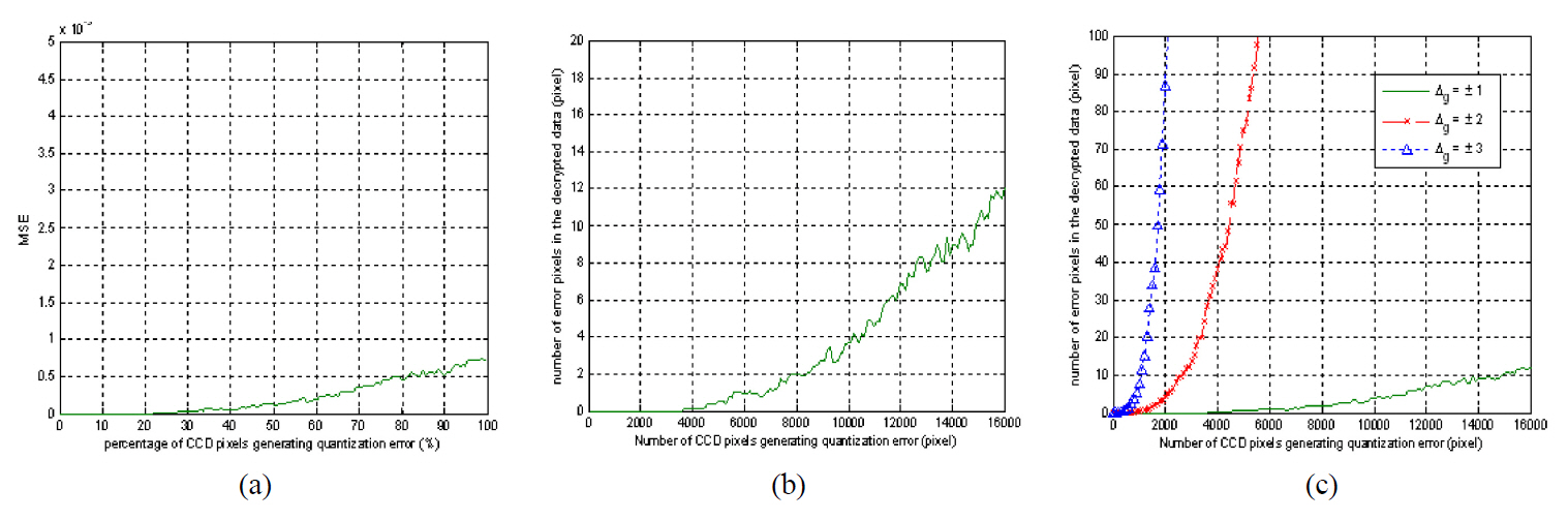
Fig. 10 shows MSE and the number of error pixels of the decrypted data versus an increase of CCD camera pixels which have gray level errors for a binary bit data encryption case. The random generated data and the encryption key shown in Fig. 3(a) and (d) are used. All graphs are an average value which is plotted by 100 random evaluations. Fig. 10(b) shows the simulation result when the gray level variation(
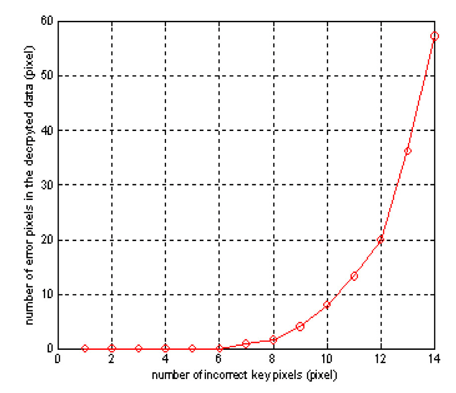
Fig. 11 shows the number of error pixels of the decrypted data versus an increase of error pixels of the security key for the case of a binary bit data encryption. The graph is also plotted by an average value which is obtained by 100 random evaluations. As show in Fig. 11, even though about 6 error pixels exist in the key compared to the correct key,the original bit data is decrypted completely. However, this error is very minor because the portion of 6 pixels error is only about 0.04% of the total key size of 128×128 pixels.When 10 error pixels exist in the key, the decrypted data has errors in about 9 pixels. This means that about 99.94%of the original data size of 128×128 pixels is reconstructed when the key has 0.06% error.
We propose a new optical encryption method based on 2-step phase-shifting digital holography for a security system.2-step phase-shifting is implemented by controlling the PZT mirror with phase steps of 0 or