검색 전체 메뉴
PDF
맨 위로
OA 학술지
Directional Emission from Photonic Crystal Waveguide Output by Terminating with CROW and Employing the PSO Algorithm
  • 비영리 CC BY-NC
  • 비영리 CC BY-NC
ABSTRACT
Directional Emission from Photonic Crystal Waveguide Output by Terminating with CROW and Employing the PSO Algorithm
KEYWORD
Photonic crystal waveguide , CROW , FDTD , Resonator , PSO , (230.0230) Optical devices , (130.3120) Integrated optics devices , (060.4510) Optical communications , (140.4780) Optical resonators
  • I. INTRODUCTION

    Photonic crystals (PCs) [1, 2] have attracted increasing attention in the past decade, due to their unique properties and potential applications in wavelength-scale photonic integrated circuits (PICs) [3-5]. These structures are artificial dielectric or metallic periodic structures in which the refractive index modulation causes stop bands for waves within a certain frequency band. These crystals have many applications because of their ability to control wave propagation.The greatest motivation behind these investigations has been the promise that they hold for miniaturizing photonic circuits [6].

    Local defects in PCs introduce defect modes within the photonic band gaps (PBGs) [4]. Thus, a point and a line defect can act as a micro-cavity and a waveguide, respectively.The resonant frequency of a defect mode is shifted by changing the size or the shape of the defect [7].

    The diffraction limit is a basic principle in classical optics. The emission of light from a structure with a subwavelength feature size will spread into a wide angle range. This is an undesirable property in PICs, because it causes mismatch loss [8, 9]. There have been some methods to obtain beam shaping effects in PCWs [10-23]. One of the methods is to reduce the radii of the surface rods in a PCW in order to create non-radiative surface modes, and then adding a periodic modulated layer of the interface cylinders to support the leaky surface modes [10]. Another method is the reshaping of the surface rods to achieve non-radiative surface modes, and then, for changing the modes to radiative ones, a PC grating layer with a row of rods with the same shape PC rods but different lattice constant is added. In this beam shaping mechanism, the added layers help to induce the electromagnetic waves at the surface to radiate their energy into a beam just a few degrees wide [26]. A directional emitter can also be achieved by covering the termination of a PCW by a self-collimating PC, in which the interference of the multiple self-collimated beams excited by the waveguide reshape the output beam[27]. Also, in another scheme, a multimode (MM) PCW is terminated by a waveguide array. The output of the MMPCW,regarded as a secondary source, splits into two beams to be launched to the waveguide array. As a result,many split light beams can be generated in the waveguide array by coupling among the waveguides. Hence the interference of these light beams after passing through the system leads to the desired directional emission [32].

    Adding a CROW to the end of the PCW can collimate the PCW output lightwave over a wide bandwidth range.These CROWs produce resonant modes, which radiate from the PC structure. These resonant modes and the lightwave emitted from the PCW can be regarded as radiating sources to interfere in free space. The total output field is determined by the vector addition of the fields radiated by the individual sources. To provide very directional patterns,it is required that the fields from the elements of the array interfere constructively in the desired direction and interfere destructively in the remaining areas. The interference produces a directional emitting beam. The mechanism providing a large operational bandwidth is due to the lower Q factor of the CROWs near the termination surface, and hence the higher radiation of the resonators [19, 24].

    In addition, researchers have introduced some structures for achieving off-axis directional beaming via engineering the PC surface layer [28, 29]. They have also presented some structures to split the output beam of PC into more than one beam in various desired directions, for which the output beam property such as angles, intensities and FWHMs are related to the engineering of the surface layer of the PCs [13, 30, 31]. These structures are very useful beam splitters in PICs to drive output lightwaves to be launched to photonic devices with more than one input or to several devices.

    However, due to the impedance mismatch and reflection at the termination of PCWs, some of the reported directional emissions are inefficient and are based on intuition and trial and error without any genuine optimization. So, the researchers have tried to improve the efficiency of the PCW directional emission [14-35].

    In many of the proposed methods, a surface layer is formed to excite the non-radiative surface modes, and then another layer is added to convert these modes to the radiative ones. The performance of the directional emission depends mainly on the coupling efficiency between PCW and the surface modes [15, 33]. Also, the coupling efficiency is sensitive to surface layer parameters such as radius,refractive index [13], and lattice period [35]. Further enhancement of the coupling efficiency is possible, if one can optimize the period of the surface cylinders, simultaneously with the other parameters.

    Some optimization methods have been used for obtaining the optimized parameters of the termination structure of the PCWs to achieve the most improved directional emission.A PCW with grating-like surface, added for highly-efficient directional emission, has been optimized by the genetic algorithm (GA) method. The interference of the lightwaves emitted from the output of the waveguide and the modes of the grating-like surface is believed to affect the directional beaming of these structures [36].

    One of the powerful algorithms that can be employed for optimization of the multidimensional problems of this kind, especially in the domain of computational electromagnetism,is the particle swarm optimization (PSO) method [37-47]. Recently, some different PC structures have been optimized by using the PSO algorithm to evaluate a fitness function [48, 49].

    In this paper, we have used the PSO algorithm to optimize the parameters of a CROW in the output surface of the PCW structure [19] to get a powerful directional beam. The paper structure is as follows. In section II, the details of the structure and simulation space will be described. In section III, the PSO algorithm will be explained.In section IV, the beam shaping effects of the non-optimized,1D-PSO optimized and 7D-PSO optimized CROW will be demonstrated. Also, the FWHM and bandwidth of each structure will be derived. The paper will be concluded in section V.

    II. DETAILS OF STRUCTURE AND SIMULATION SPACE

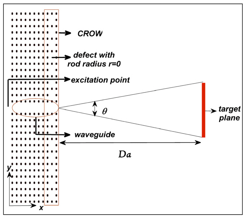
    We have considered a PC structure with a square lattice of dielectric rods in air, as shown in FIG. 1. The relative dielectric constant of the rods is 11.56, corresponding to that of InGaAsP-InP semiconductor material at 1.55 ㎛ wavelength [19], and the rod cross-sectional diameter is chosen to be 0.36a, where a is the PC lattice constant. For TM polarization with the electric field Ez parallel to and magnetic field perpendicular to the rods' axis with components Hx and Hy, the PBG of the PC structure, derived by either broadband Gaussian pulse excitation or the plane wave expansion (PWE) method, is in the normalized frequency

    image

    range of 0.306-0.439, where ω is the angular frequency,and c is the speed of light in free space [19, 24]. All the results are presented for TM polarization and have been obtained with the 2D-FDTD method with perfectly matched layer boundary conditions. In the simulations we have used 31×11 dielectric rods in free space. We have

    considered the spatial step in the FDTD method to be Δx=d/10, where d is the cross-sectional diameter of the rods.We have chosen a waveguide by removing one row of the rods along the x-direction and CROW by making defects at regular intervals of 2a at the PCW termination by changing the diameter of the central rod of the resonators.In this structure each resonator can radiate to free space.The total field of the array is determined by the vector summation of the radiated fields of the resonators, the result of which is the radiation pattern of the structure. The excitation point, the waveguide, the CROW with defect rod diameter of d=0, and the target plane as fitness function in PSO through which the power flow has to be maximized are depicted in FIG. 1. The target plane is defined at a distance of Da from the waveguide exit, where D is a constant number, within an angle of θ degrees, as shown in FIG. 1.

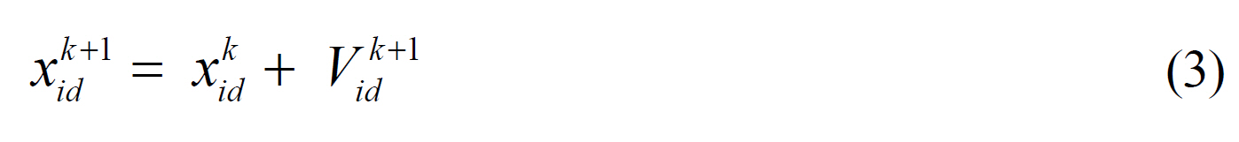
    The incident lightwave signal is a modulated Gaussian:

    image

    where f0 is the resonant frequency of the resonators with defect diameter of d=0, t is time, T0 is the time of the peak and σ is the width controller of the Gaussian pulse[24].

    In this paper, the FDTD software was prepared in C++and MATLAB and was executed on a Pentium IV quad core CPU computer with processing capacity of 2.84 GHz and 3.25 Gb of RAM.

    III. AN OVERVIEW OF THE PARTICLE SWARM OPTIMIZATION METHOD

    PSO is a stochastic evolutionary optimization method based on the movement and intelligence of swarms proposed first by Kennedy and Eberhart [37].

    In this method, the population of potential solutions to the problem under consideration is used to probe the search space. Each particle adjusts its movement according to its own and its companions’ movement experiences.This process is continued until the best solution is achieved[46]. Both genetic algorithm (GA) and PSO are similar in the sense that both are population-based search methods and search for the optimal solution by updating generations.Unlike GA, PSO has no evolution operators such as crossover and mutation. Also, GA and PSO employ different strategies and computational efforts. PSO has been demonstrated to be superior to the genetic algorithm for certain difficult optimization problems [43]. Furthermore, compared to the genetic algorithm, PSO is easier to be implemented and has lower parameters to be controlled. Moreover,researchers have achieved improved and simplified models in the PSO algorithm, for example local PSO and Boolean PSO. However, specialists are trying to find more simplified models. PSO has already given some promising results in the domain of photonics in particular and electromagnetics in general [44-51].

    In each PSO problem a “fitness function” is defined to guide the particles through the solution space to that position where the fitness function has its target value. Each particle is treated as a mass-less and volume-less point in a D-dimensional space. The ith particle is represented as xi=(xi1, xi2,?, xiD). A “best position” is a place that the fitness function has a value closest to its final desired value. The best previous position of the ith particle is named “personal best position”, which gives the best fitness value for that particle, is represented as pbesti=(pi1, pi2, ?piD). The best particle among all the particles in the population is named “global best position” and represented by gbest=(g1, g2, ?gD). The global best position does not have the superscript identifying the particle. Velocity, the rate of position change for the ith particle, is represented as Vi=(Vi1, Vi2, ViD). At every iteration, the velocity and the position of each particle are updated by using the two best values according to the following equations:

    image
    image

    where k is the iteration number, d = 1, 2, …, D, i = 1, 2, …, N, and N is the size of the population (swarm). c1 and c2 are two positive values called acceleration constants,rand1( ) and rand2( ) are two independent random numbers that are uniformly distributed between 0 and 1 and are used to stochastically vary the relative attraction of pbesti and gbest. ω is the inertial weight, a constant acting as the inertia of the particle, which determines that how the velocity of particles in (k+1)th iteration are affected by the velocities in kth iteration. The inertial weight improves the performance of the PSO algorithm [41, 49]. As the iteration count increases, each particle in the swarm will progressively be guided to the position where the fitness function has its desired value. One of the most important issues encountered during the PSO implementation is the ability to control the search space of the swarm. Without any boundary or limit on the velocity, particles could essentially fly out of the physically meaningful solution space. One approach for solving this problem is to simply assign a maximum allowed velocity, Vmax. It has been found that without inertial weight (ω =1), Vmax around 10-20% of the dynamic range of each dimension is the best. We hoped that the introduction of inertial weight would negate the need for Vmax; however, we noticed that the PSO can be performed better if Vmax in each dimension is set equal to the dynamic range of that dimension [50].

    Some experimental results demonstrated that the global best model converges quickly on problem solutions but has a weakness for becoming trapped in local optima, while the local best model converges slowly on problem solutions but is able to “flow around” local optima, as the individuals explore different regions. The global best model is strongly recommended for the single-modal objective functions, while a variable neighborhood model is recommended for the multi-modal objective functions. For the local best model Eqs. (2) and (3) do not alter significantly. But the subscript g (global) is changed to l (local) [40].

    When the solution space is discrete, Boolean PSO is preferred, and Eqs. (2) and (3) change by replacing additions and products with exclusive OR and AND operations,respectively. A full description of Boolean PSO and conventional PSO can be found in [44, 50].

    IV. EFFECTS OF PHOTONIC CRYSTAL WAVEGUIDE SURFACE PARAMETERS ON OUTPUT POWER

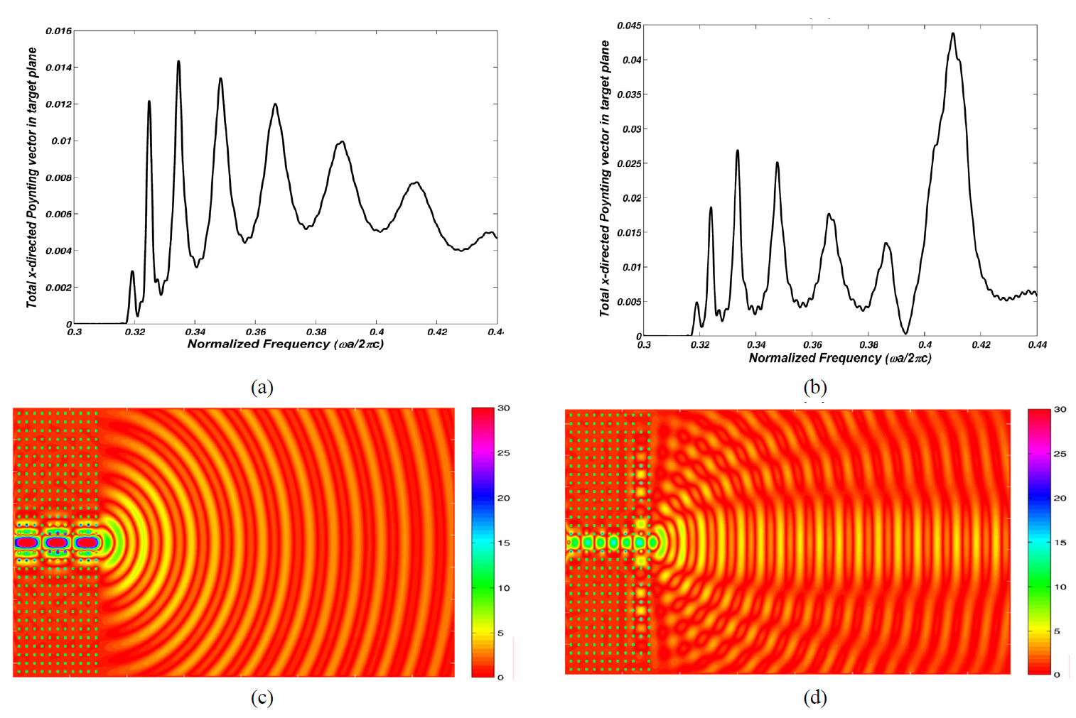
    We consider two PC waveguides with parameters described above, without and with CROW surface structure with defect rods diameter of d=0. We launch an impulse lightwave signal, very narrow Gaussian source to the PCW, the frequency spectrum of which contains the total band-gap of the PC. FIGs. 2a and 2b show the spectra of the total x-directed Poynting vector at the target plane of the structures at a distance of 35a (D=35) and the angle ofθ = 4° , depicted in FIG. 1. The spectra have been obtained by discrete Fourier transform (DFT) of the electric and magnetic fields and the Poynting vector. The spectra are depicted in normalized frequency range of 0.3-0.44 coinciding with the band-gap of the PC. As we can see and have explained previously [19], the CROW in the PCW surface has caused the beam shaping effect and therefore more power is received by the target plane in the whole frequency range. As shown, the maximization of x-directed Poynting vector by means of CROW is more sensible in a special range of normalized frequency, say 0.4-0.42, because of the maximum coupling between the waveguide and the resonators and minimum quality factor(Q) of the resonators in this range. The resonators’lightwaves can radiate to free space, interfere with the waveguide output, cause the beam shaping effect and increase the power transmission to the target plane in this

    specified bandwidth. FIGs. 2c and 2d show the electric field distributions in normalized frequency of 0.334 and 0.410, for which the maximum power is received by the target plane from the PC waveguides without and with the CROW surface, respectively. As illustrated, the x-directed Poynting vector received by the target plane from the PC structure with CROW surface is 3.044 times higher than that of the structure without CROW.

       4.1. Optimization of the Crow Cavity Rods with the Same Diameter

    Further improvement of the directional emission of the PCW with CROW structures is possible by variations of the diameters of the defect rods. First, we assume the same defect rod diameter and try to optimize the diameter by a 1D-PSO algorithm. There is a one dimensional solution space that can be searched for the optimum solution by using the PSO algorithm. Since the purpose of the optimization process is to increase the PCW directional emission,we choose the fitness function as the power (x-directed Poynting vector) received by the target plane located at the distance 35a (D=35) and the angle of θ =4° from the PCW output (FIG. 1). Maximization of the power received by the target plane is the aim of optimization.

    In this optimization process the same diameters of 0.21a have been derived for the defect rods. FIG. 3a shows the spectrum of the total x-directed Poynting vector received by the target plane of this optimized structure. As we can see the normalized frequency for which the maximum power is received by the target plane is shifted to 0.344.Since the frequencies have been normalized to the lattice constant a, manufacturers can choose suitable a value to shift the maximum power wavelength to a desired wavelength,say 1.55 ㎛. The maximum power received by the target plane is 2.79 times higher than that of the previous non-optimized structure.

    In exchange for the greater power received by the target plane and more intensive beam, the normalized bandwidth of the beam shaping effect decreased from 0.014 to lower than its half amount, 0.0052 which can be deduced by comparing FIGs. 2b and 3a. FIG. 3b demonstrates the electric field distribution in normalized frequency of 0.344.The stronger beam focusing compared to that of the previous structure is obvious.

    Optimization of other parameters of the defect rods,such as dielectric constant, was not executed because of the probability of obtaining impractical results.

    In this 1D-PSO algorithm we have chosen 80 particles for global best algorithm with acceleration constants c1=c2=1.5, linearly descending inertial weight from 0.95 to 0.2, Vmax= 0.2 and ε =10-3. When the condition of gbest(k)- gbest(k-1) < ε was satisfied, the PSO algorithm was stopped. The PSO with 20 iterations was sufficient for this condition.

    The execution time for optimization was 148 hours with the computer described in section II.

       4.2. Optimization of the Crow Cavity Rods with Different Diameter

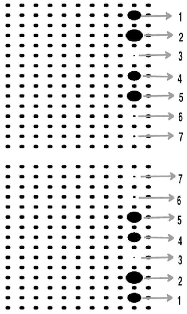
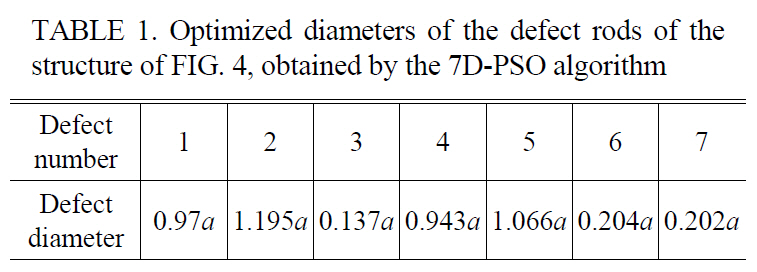
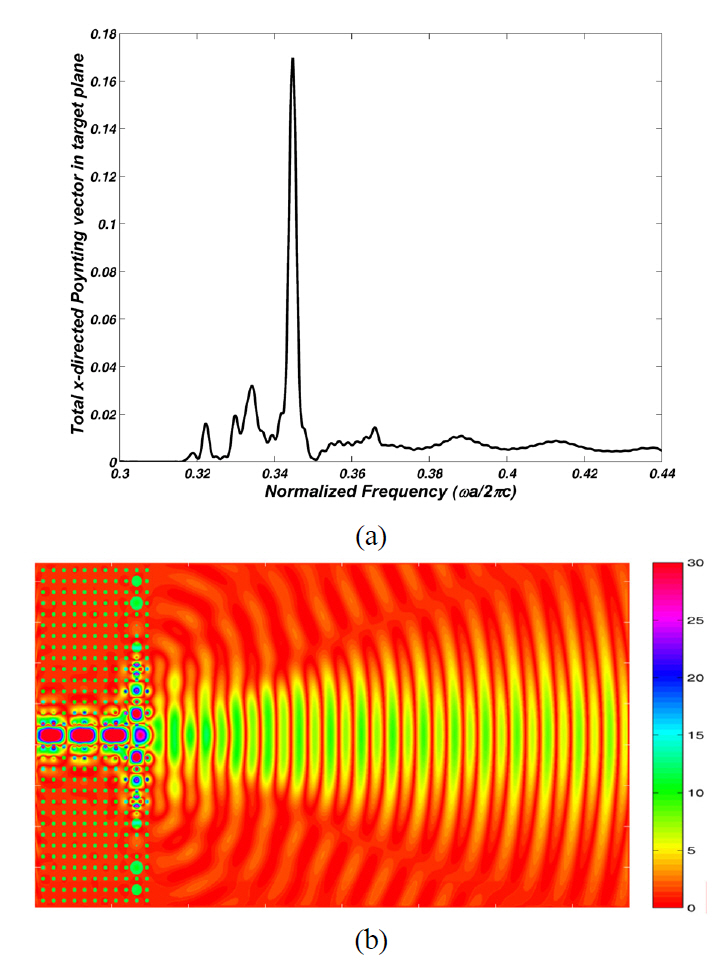
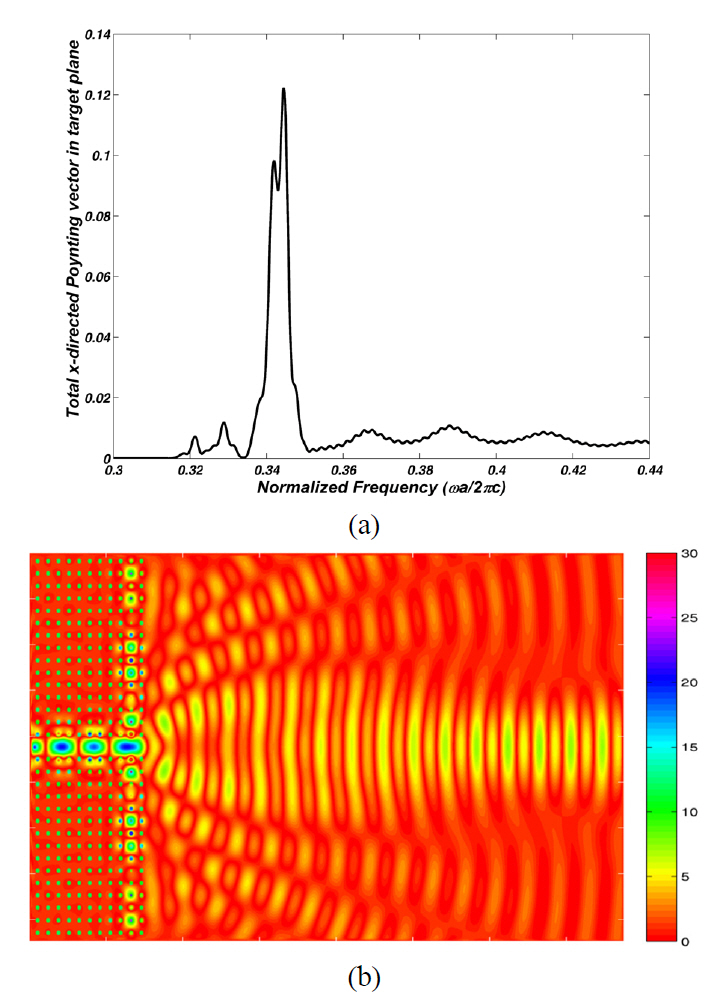
    Optimization of the combination of the diameters of the CROW rods can cause better results in the beam focusing effect. Therefore, we have numbered the defect rods consecutively from the top of the waveguide, as shown in FIG. 4. Since this structure has seven resonators in both sides of the waveguide, due to the symmetry of the structure,we have seven defect rods to be optimized. So, we have a seven dimensional (7D) solution space that can be searched for the optimum solution by using a 7D-PSO algorithm.The fitness function is the same as that of the previous subsection. The optimization results for the diameters of the defect rods are given in TABLE 1. FIG. 5a depicts the spectrum of the total x-directed Poynting vector received by the target plane of this optimized structure. The maximum power has been received in the normalized frequency of 0.344. The electric field distribution in this frequency is shown in FIG. 5b. The 7D-PSO optimized structure has caused 3.875 and 1.389 times improvement in the received power by the target plane compared to the previous non-optimized and 1D-PSO optimized structure, respectively.

    [TABLE 1.] Optimized diameters of the defect rods of thestructure of FIG. 4, obtained by the 7D-PSO algorithm

    label

    Optimized diameters of the defect rods of thestructure of FIG. 4, obtained by the 7D-PSO algorithm

    The angle θ in fitness function depicted in FIG. 1 was chosen to be 4°. As can be intuitively deduced from electric field distribution in FIGs. 3b and 5b, if we had chosen higher θ , the improvement in received power by target plane would have been higher than 1.389 compared to the 1D-PSO. In exchange for the higher received power by target plane and more intensive beam, the normalized frequency bandwidth of beam shaping effect is decreased from 0.052 to lower than its half amount, 0.0023. The higher directivity and intensity caused the lower bandwidth because the directionality and intensity deeply depend on the resonators of the optimized structure. Comparison of FIGs. 2b, 3a and 5a confirms this effect.

    Although global best model converges quickly on problem solutions, in this 7D-PSO algorithm, it was not appropriate because of trapping in local optima. So, we divided the solution space of the PSO to six different explore regions to use local algorithm of PSO. In each region we had 70 particles with acceleration constants of c1=c2=1.5, linearly descending inertial weight from 0.95 to 0.4, Vmax=2 and ε =10-3. When the condition of lbest(k) -lbest(k-1) < ε and the iteration count k > 25 were simultaneously satisfied, the PSO algorithm was stopped.

    In both 1D and 7D-PSO algorithms, the boundary values of the defect rods' diameters and the particles’ velocities have been assigned. The diameters of the defect rods must vary from 0 to 1.64a (2a-0.36a=1.64a) and the velocity of particles must be in the range of [-Vmax ,+Vmax].

    The PSO with 25 iterations was sufficient for each of

    the explored regions that were simultaneously optimized.The execution time for optimization of each region was about 430 hours with the computer described in section II.

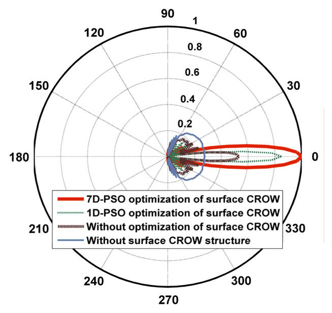
    FIG. 6 shows the polar diagram of the normalized electric field pattern in the azimuthal plane at a distance of 35a from the output of PCW for the four analyzed and simulated structures. We can see the beam focusing improvement in each step of the above cases. In each step, the power at the angles out of the specific narrow angle in front of the PCW decreases and their power transfers to the main lobe lying in this specific angle. So, the main lobe becomes very intensive.

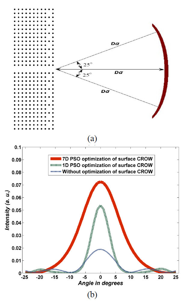
    To compare the FWHM of output beams, we measure the Poynting vector in radius direction in cylindrical coordinate system, in the view angle range of -25° to +25°in free space shown in FIG. 7a, the results of which are illustrated in FIG. 7b. Each diagram in this figure has been plotted for the normalized frequency in which the maximum power is received by the target plane of FIG. 1 in each structure. The red (solid), green (dashed) and blue(dotted) lines describe the power pattern in the normalized frequencies of 0.344, 0.344 and 0.410 for 7D-PSO optimized,1D-PSO optimized and non-optimized CROW surface structure, respectively. The blue (dotted) diagram belongs to the structure without optimization which the defect rods diameter are d=0. Its FWHM is 10°. Implementation of the 1D-PSO algorithm has caused the green (dashed) diagram with

    FWHM of 7°. This FWHM shows a decrement of 1.43 times compared to the non-optimized structure. The increased intensity and beam shaping effect is significant in this structure.In the 7D-PSO algorithm of the red (solid) diagram, all the minor lobes have been eliminated and the main lobe becomes very intensive, but the FWHM is increased to 14°; 1.4 and 2 times increments compared to the non-optimized and 1D-PSO optimized structures, respectively. Although the FWHM becomes higher than the previous cases, the power distribution is very significant in the main lobe and very low (approximately zero) in the angles out of the main lobe.

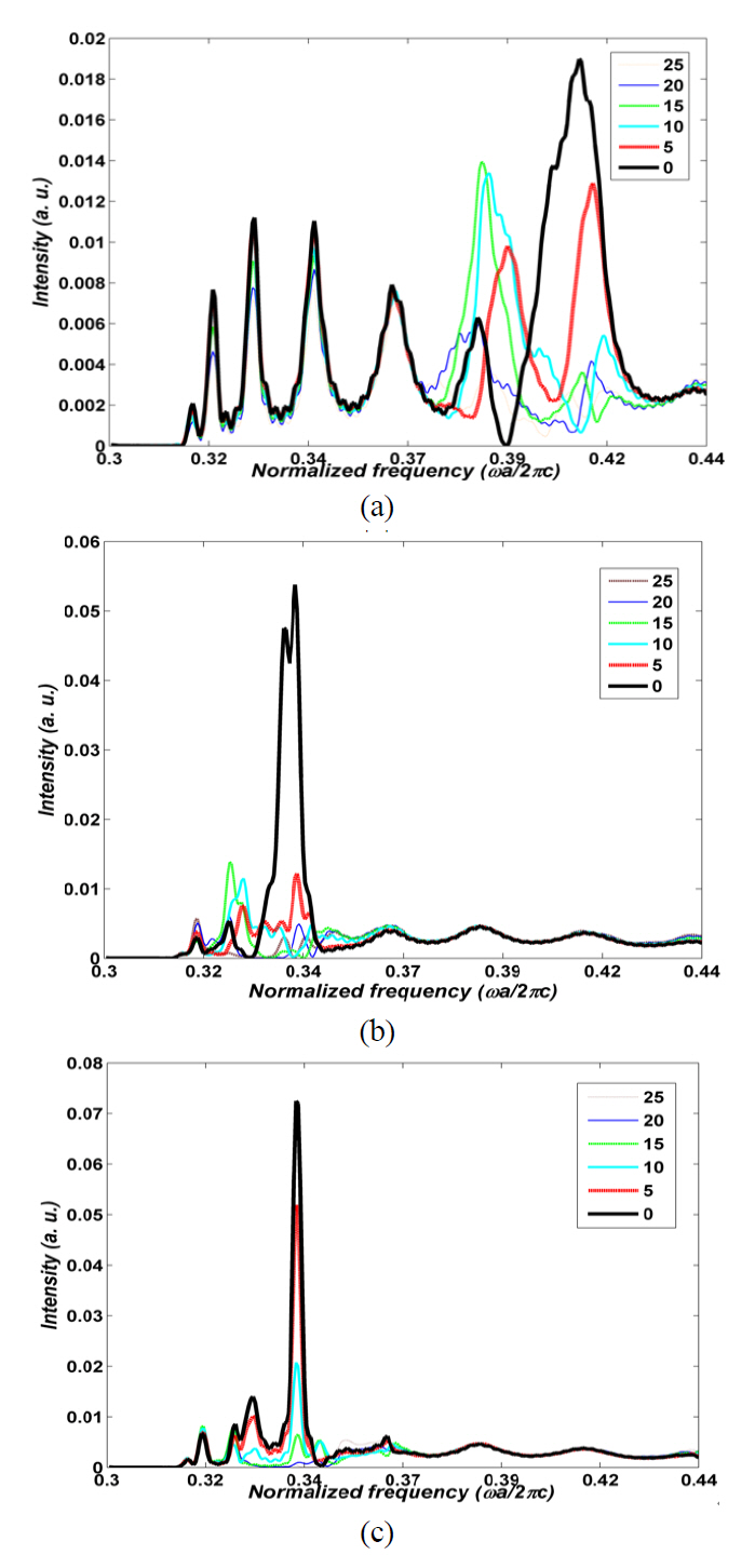
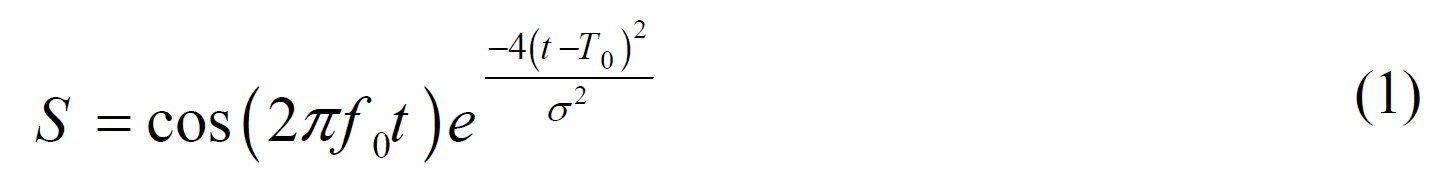
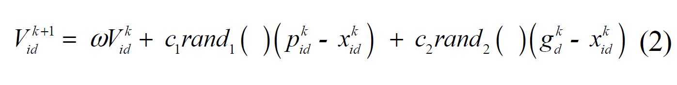
    For more study of the intensity, FWHM and bandwidth

    of beam shaping of the PCW output, we launch similar pulses to the non-optimized, 1D-PSO optimized and 7D-PSO optimized CROW surface structures. FIG. 8a-8c depict the spectra of r-directed Poynting vector of some points in various angles between 0° to 25° on the arc of FIG. 7a for three cases of the CROW surface structure. The measured powers at the angle of 0° of the 1D-PSO optimized and 7D-PSO optimized CROW surface structures increase compared to the non-optimized one, which means that the radiated beams have become more focused around the 0° angle.

    The ratio of the intensities at angles of 5° and 0° of non-optimized, 1D-PSO optimized and 7D-PSO optimized beams in their maximum power transfer frequency are 0.5,0.21 and 0.72, respectively, which confirms that the FWHM of 1D-PSO optimized and 7D-PSO optimized beams are the least and the most, respectively.

    FIGs. 8a-8c also show the frequency bandwidth of the higher intensity of detector at 0° angle. These confirm the lower frequency bandwidth of the beam focusing for the more intensive output structure.

    V. CONCLUSION

    In this paper, we have designed two photonic crystal waveguide (PCW) structures with focused output beams in order to achieve more coupling between photonic devices and decrease the mismatch losses in PICs. We have used the particle swarm optimization (PSO) algorithm for PCW terminated by a CROW structure. We could focus some of the powers of the minor lobes to the main lobe by one dimensional (1D) optimization of the same resonator rods diameter. In this optimized structure the intensity calculated by the fitness function of the PSO increases and the FWHM of the main lobe decreases. But there were some undesirable minor lobes that should be eliminated.So, we used 7D-PSO algorithm to optimize the various diameters of the seven resonator's rods. The power of minor lobes became very low and most of the powers were focused to the main lobe. So, the main lobe radiated power became more intensive. But the FWHM of the main lobe increased compared to the non-optimized and 1Doptimized structure. We have also shown that the higher directivity and intensity causes the lower bandwidth, because the directionality and intensity heavily depend on the resonators in the optimized structure. The method can be extended for simulation and optimization of the photonic crystal power splitters and multi/demultiplexers.

참고문헌
  • 1. Yablonovitch E 1987 Inhibited spontaneous emission in solid-state physics and electronics [Phys. Rev. Lett.] Vol.58 P.2059-2062 google cross ref
  • 2. John S 1987 Strong localization of photons in certain disordered dielectric superlattices [Phys. Rev. Lett.] Vol.58 P.2486-2489 google cross ref
  • 3. Meier M, Mekis A, Dodabalapur A, Timko A, Slusher R. E, Joannopoulos J. D, Nalamasu O 1999 Laser action from two-dimensional distributed feedback in photonic crystals [Appl. Phys. Lett.] Vol.74 P.7-9 google cross ref
  • 4. Umemori K, Kanamori Y, Hane K 2006 Photonic crystal waveguide switch with a microelectromechanical actuator [Appl. Phys. Lett.] Vol.89 P.021102-1-021102-3 google cross ref
  • 5. Sugimoto Y, Lan S, Nishikawa S, Ikeda N, Ishikawa H, Asakawa K 2002 Design and fabrication of impurity bandbased photonic crystal waveguides for optical delay lines [Appl. Phys. Lett.] Vol.81 P.1946-1948 google cross ref
  • 6. Javan A. R. M, Granpayeh N 2008 Terahertz wave switch based on photonic crystal ring resonators [Opt. Quantum Electron.] Vol.40 P.695-705 google cross ref
  • 7. Kee C. S, Ko D. K, Lee J 2006 Functional optical filters based on two-dimensional photonic crystals [Korean Phys. Soc.] Vol.48 P.978-981 google
  • 8. Kurt H 2009 Limited-diffraction light propagation with axiconshape photonic crystals [J. Opt. Soc. Am. B] Vol.26 P.981-986 google cross ref
  • 9. Caglayan H, Bulu I, Ozbay E 2006 Beaming of electromagnetic waves emitted through a subwavelength annular aperture [J. Opt. Soc. Am. B] Vol.23 P.419-422 google cross ref
  • 10. Moreno E, Garcia-Vidal F. J, Martin-Moreno L 2004 Enhanced transmission and beaming of light via photonic crystal surface modes [Phys. Rev. B] Vol.69 P.121402-1-121402-4 google cross ref
  • 11. Kramper P, Agio M, Soukoulis C. M, Birner A, Muller F, Wehrspohn R. B, Gosele U, Sandoghdar V 2004 Highly directional emission from photonic crystal waveguides of subwavelength width [Phys. Rev. Lett.] Vol.92 P.113903-1-113903-4 google cross ref
  • 12. Kurt H 2008 Theoretical study of directional emission enhancement from photonic crystal waveguides with tapered exits [IEEE Photon. Technol. Lett.] Vol.20 P.1682-1684 google cross ref
  • 13. Morrison S. K, Kivshar Y. S 2005 Engineering of directional emission from photonic-crystal waveguides [Appl. Phys. Lett.] Vol.86 P.08111-1-08111-3 google
  • 14. Frei W. R, Tortorelli D. A, Johnson H. T 2005 Topology optimization of a photonic crystal waveguide termination to maximize directional emission [Appl. Phys. Lett.] Vol.86 P.111114-1-111114-3 google cross ref
  • 15. Gan D, Qi Y, Yang X, Ma J, Cui J, Wang C, Luo X 2008 Improved directional emission by resonant defect cavity modes in photonic crystal waveguide with corrugated surface [Appl. Phys. B] Vol.93 P.849-852 google cross ref
  • 16. Chen C. C, Pertsch T, Iliew R, Lederer F, Tunnermann A 2006 Directional emission from photonic crystal waveguides [Opt. Express] Vol.14 P.2423-2428 google cross ref
  • 17. Tang D. H, Chen L. X, Ding W. Q 2006 Efficient beaming from photonic crystal waveguides via self-collimation effect [Appl. Phys. Lett.] Vol.89 P.131120-1-131120-3 google cross ref
  • 18. Zhang Y. L, Zhang Y, Li B. J 2007 Highly-efficient directional emission from photonic crystal waveguides for coupling of freely propagated terahertz waves into Si slab waveguides [Opt. Express] Vol.15 P.9281-9286 google cross ref
  • 19. Zhu Z. H, Ye W. M, Ji J. R, Yuan X. D, Zen C 2007 Enhanced transmission and directional emission via coupledresonator optical waveguides [Appl. Phys. B] Vol.86 P.327-331 google cross ref
  • 20. Li Z. F, Koray A, Ekmel O 2007 Highly directional emission from photonic crystals with a wide bandwidth [Appl. Phys. Lett.] Vol.91 P.121105-1-121105-3 google cross ref
  • 21. Bulu I, Caglayan H, Ozbay E 2005 Beaming of light and enhanced transmission via surface modes of photonic crystals [Opt. Lett.] Vol.30 P.3078-3080 google cross ref
  • 22. Chung K. B 2008 Properties of surface modes used for directionalemission from photonic crystal waveguides [J. Opt. Soc. Korea] Vol.12 P.7-12 google cross ref
  • 23. Chung K. B 2008 Effects of surface termination on directional emission from photonic crystal waveguides [J. Opt. Soc. Korea] Vol.12 P.13-18 google cross ref
  • 24. Bozorgi M, Granpayeh N 2010 Duality of photonic crystal radiative structures and antenna arrays [J. Opt. Soc. Korea] Vol.14 P.438-443 google cross ref
  • 25. Wang Q, Cui Y. P, Yan C. C, Zhang L. L, Zhang J. Y 2008 Highly efficient directional emission using a coupled multi-channel structure to a photonic crystal waveguide with surface modification [J. Phys. D: Appl. Phys.] Vol.41 P.105110-1-105110-5 google cross ref
  • 26. Moussa R, Wang B, Tuttle G, Koschny Th, Soukoulis C. M 2007 Effect of beaming and enhanced transmission in photonic crystals [Phys. Rev. B] Vol.76 P.235417-1-235417-8 google cross ref
  • 27. Tang D. H, Chen L. X, Ding W. Q 2006 Efficient beaming from photonic crystal waveguides via self-collimation effect [Appl. Phys. Lett.] Vol.89 P.131120-1-131120-3 google cross ref
  • 28. Chen H, Zeng Y, Chen X, Wang J, Lu W 2008 Modulation of focus using photonic crystal waveguide [Phys. Lett. A] Vol.372 P.5096-5100 google cross ref
  • 29. Caglayan H, Bulu I, Ozbay E 2008 Off-axis directional beaming via photonic crystal surface modes [Appl. Phys. Lett.] Vol.92 P.092114-1-092114-3 google cross ref
  • 30. Liang W. Y, Dong J. W, Wang H. Z 2007 Directional emitter and beam splitter based on self-collimation effect [Opt. Express] Vol.15 P.1234-1239 google cross ref
  • 31. Jiang L, Jia W, Li H, Li X, Cong C, Shen Z 2009 Inverse design for directional emitter and power splitter based on photonic crystal waveguide with surface corrugations [J. Opt. Soc. Am. B] Vol.26 P.2157-2160 google cross ref
  • 32. Wang Q, Zhang J, Yan C, Cui Y 2009 Beaming effect in multimode photonic crystal by using coupled waveguides [Phys. Lett. A] Vol.373 P.1097-1100 google cross ref
  • 33. W. ?migaj 2007 Model of light collimation by photonic crystal surface modes [Phys. Rev. B] Vol.75 P.205430-1-205430-8 google cross ref
  • 34. Chen H. B, Chen X. S, Wang J, Lu W 2008 Tunable beam direction and transmission of light using photonic crystal waveguide [Physica B] Vol.403 P.4301-4304 google cross ref
  • 35. Frei W. R, Tortorelli D. A, Johnson H. T 2007 Geometry projection method for optimizing photonic nanostructures [Opt. Lett.] Vol.32 P.77-79 google cross ref
  • 36. Jiang L, Li H, Jia W, Li X, Shen Z 2009 Genetic optimization of photonic crystal waveguide termination for both on-axis and off-axis highly efficient directional emission [Opt. Express] Vol.17 P.10126-10135 google cross ref
  • 37. Kennedy J, Eberhart R. C “Particle swarm optimization” P.1942-1948 google
  • 38. Kennedy J, Eberhart R. C, Shi Y 2001 Swarm Intelligence google
  • 39. Chan F. T. S, Tiwari M. K 2007 Swarm Intelligence Focus on Ant and Particle Swarm Optimization google
  • 40. Nedjah N, Coelho L. S, Mourelle M 2006 Swarm Intelligent Systems google
  • 41. Yao Y. Li D, Yao J, Chen W 2005 A particle swarm optimization algorithm for beam angle selection in intensitymodulated radiotherapy planning [Phys. Med. Biol.] Vol.50 P.3491-3514 google cross ref
  • 42. Chamaani S, Mirtaheri S. A, Teshnehlab M, Shoorehdeli M. A, Seydi V 2008 Modified multi-objective particle swarm optimization for electromagnetic absorber design [PIER] Vol.79 P.353-366 google cross ref
  • 43. Kennedy J, Spears W. M “Matching algorithms toproblems: an experimental test of the particle swarm andsome genetic algorithms on multi modal problem generator” P.28-83 google
  • 44. Marandi A, Afshinmanesh F, Shahabadi M, Bahrami F “Boolean particle swarm optimization and its application to the design of a dual-band dual-polarized planar antenna” P.3212-3218 google
  • 45. Li Y 2009 Hybrid intelligent approach for modeling and optimization of semiconductor devices and nanostructures [Comput. Mater. Sci.] Vol.45 P.41-51 google cross ref
  • 46. Djavid M, Mirtaheri S. A, Abrishamian M. S 2009 Photonic crystal notch filter design using particle swarm optimization theory and finite difference time domain analysis [J. Opt. Soc. Am. B] Vol.26 P.849-853 google cross ref
  • 47. Darki B. S, Granpayeh N 2010 Improving the performance of a photonic crystal ring-resonator-based channel drop filter using particle swarm optimization method [Opt. Comm.] Vol.283 P.4099-4103 google cross ref
  • 48. Marandi A, Afshinmanesh F, So P. P. M “Design of a highly focused photonic crystal lens using boolean particle swarm optimization” P.931-932 google
  • 49. Kumar M. S, Menabde S, Yu S, Park N 2010 Directional emission from photonic crystal waveguide terminations using particle swarm optimization [J. Opt. Soc. Am. B] Vol.27 P.343-349 google cross ref
  • 50. Robinson J, R-Samii Y 2004 Particle swarm optimization in electromagnetics [IEEE Trans. Antennas Propag.] Vol.52 P.397-407 google cross ref
  • 51. Afshinmanesh F, Marandi A, So P. P. M, Gordon R 2008 Proposal for compact optical filters using large index step binary supergratings [IEEE Photon. Technol. Lett.] Vol.20 P.676-678 google cross ref
이미지 / 테이블
  • [ FIG. 1. ]  Waveguide structure, CROW with defect rod diameter of d=0 at surface, excitation point and the target plane as fitness function in PSO through which the power flow has to be maximized.
    Waveguide structure, CROW with defect rod diameter of d=0 at surface, excitation point and the target plane as fitness function in PSO through which the power flow has to be maximized.
  • [ FIG. 2. ]  Spectra of the total x-directed Poynting vector received by the target plane at a distance of 35a (D=35) and the angle of θ = 4°depicted in FIG. 1, for (a) a PCW without CROW surface layer and (b) a PCW with non-optimized CROW surface layer with defect rod diameter of d=0. Electric field distributions in the frequency of the maximum power transfer of (c) the first structure at normalized frequency of 0.334 and (d) the second structure at normalized frequency of 0.410. These two frequencies are obtained from the peaks of the spectra (a) and (b), respectively.
    Spectra of the total x-directed Poynting vector received by the target plane at a distance of 35a (D=35) and the angle of θ = 4°depicted in FIG. 1, for (a) a PCW without CROW surface layer and (b) a PCW with non-optimized CROW surface layer with defect rod diameter of d=0. Electric field distributions in the frequency of the maximum power transfer of (c) the first structure at normalized frequency of 0.334 and (d) the second structure at normalized frequency of 0.410. These two frequencies are obtained from the peaks of the spectra (a) and (b), respectively.
  • [ FIG. 3. ]  (a) Spectrum of the total x-directed Poynting vectorreceived by the target plane for a PCW with 1D-PSOoptimized CROW surface layer, (b) electric field distributionof the structure in the normalized frequency of maximumpower transfer of 0.344 which is obtained from the peak of thespectrum (a).
    (a) Spectrum of the total x-directed Poynting vectorreceived by the target plane for a PCW with 1D-PSOoptimized CROW surface layer, (b) electric field distributionof the structure in the normalized frequency of maximumpower transfer of 0.344 which is obtained from the peak of thespectrum (a).
  • [ FIG. 4. ]  The defect rods are consecutively numbered from thetop of the waveguide as the 7D-PSO algorithm parameters.
    The defect rods are consecutively numbered from thetop of the waveguide as the 7D-PSO algorithm parameters.
  • [ TABLE 1. ]  Optimized diameters of the defect rods of thestructure of FIG. 4, obtained by the 7D-PSO algorithm
    Optimized diameters of the defect rods of thestructure of FIG. 4, obtained by the 7D-PSO algorithm
  • [ FIG. 5. ]  (a) Spectrum of the total x-directed Poynting vectorreceived by the target plane for a PCW with 7D-PSOoptimized CROW surface layer depicted in FIG. 4, (b)electric field distribution of the structure in the normalizedfrequency of maximum power transfer of 0.344, which isobtained from the peak of the spectrum (a).
    (a) Spectrum of the total x-directed Poynting vectorreceived by the target plane for a PCW with 7D-PSOoptimized CROW surface layer depicted in FIG. 4, (b)electric field distribution of the structure in the normalizedfrequency of maximum power transfer of 0.344, which isobtained from the peak of the spectrum (a).
  • [ FIG. 6. ]  Polar diagram of the normalized electric field patternin the azimuthal plane at distance of 35a from the output of thePCW for four waveguide structures of 7D-optimized,1D-optimized, without optimization, and without CROWsurface structure.
    Polar diagram of the normalized electric field patternin the azimuthal plane at distance of 35a from the output of thePCW for four waveguide structures of 7D-optimized,1D-optimized, without optimization, and without CROWsurface structure.
  • [ FIG. 7. ]  (a) An arc with radius 35a (D=35) and angle of θ =50°in front of the waveguide, (b) The r-directed Poynting vector over the arc for 7D-PSO optimized (red solid line), 1D-PSO optimized (green dashed line) and non-optimized CROW surface structure (blue dotted).
    (a) An arc with radius 35a (D=35) and angle of θ =50°in front of the waveguide, (b) The r-directed Poynting vector over the arc for 7D-PSO optimized (red solid line), 1D-PSO optimized (green dashed line) and non-optimized CROW surface structure (blue dotted).
  • [ FIG. 8. ]  Spectra of r-directed Poynting vector obtained by thedetectors at angles of 0° to 25° with angle intervals of 5° for(a) non-optimized (b) 1D-PSO optimized, and (c) 7D-PSOoptimized CROW surface structure.
    Spectra of r-directed Poynting vector obtained by thedetectors at angles of 0° to 25° with angle intervals of 5° for(a) non-optimized (b) 1D-PSO optimized, and (c) 7D-PSOoptimized CROW surface structure.
(우)06579 서울시 서초구 반포대로 201(반포동)
Tel. 02-537-6389 | Fax. 02-590-0571 | 문의 : oak2014@korea.kr
Copyright(c) National Library of Korea. All rights reserved.