Recently, RoF technologies have received much interest to accommodate the increase in traffic bandwidth and diversity of services [1-3]. The advantages of RoF technologies include better utilization of optical fiber characteristics, such as low loss and wide bandwidth. Other advantages of RoF technologies include cost-effectiveness achieved by reducing the size of radio base station (RBS) units and ease of upgrade. Moreover, the transmission channel capacity and total number of users in single RoF networks can be increased by using a subcarrier multiplexing (SCM) technology for multi-service environments [4, 5]. Optical SCM technology can simultaneously multiplex and transmit multiple RF signals at different frequencies on a single wavelength.
An RoF system for in-building wireless communications was previously proposed, and the RoF technology is often evaluated as one of the simplest solutions for future wireless broadband access [6] such as worldwide interoperability for microwave access (WiMAX, IEEE 802.16). Although a number of different spectral bands are possible, the IEEE 802.16a standard suggests the use of the frequency band ranging from 2 GHz to 11 GHz, and the SCM technology can be applied to the distribution of multiple RF signals in this band.
However, for the SCM signal transmission environments with high subcarrier frequencies and long transmission distances, impairment from the optical fiber channel is unavoidable such as the fiber nonlinearities (SPM or cross-phase modulation, XPM) and the dispersion-induced power penalty (DIPP) of the optical fiber channel that alters the first null point of the fiber response according to different subcarrier frequencies and transmission distances[7]. To compensate for the DIPP characteristic, the combined effect of SPM and dispersion in millimeter-wave optical transmission systems was previously investigated [8, 9]. The frequency chirp generated by the combination of fiberinduced SPM and chromatic dispersion leads to improving the frequency-length product of the optical link [8], and the dispersion tolerant transmission of 8 Mb/s pseudo-random binary sequence (PRBS) signal at 7 GHz over 75 km standard SMF (SSMF) link has been experimentally demonstrated[9]. Although the previous studies showed the feasibility of the fiber dispersion compensation technique by using the inherent characteristic of fiber nonlinearity such as SPM, not by avoiding them [8, 9], their analyses were limited to transmission systems with a single subcarrier and the mitigation of the system parameter was not investigated.
There are also many pre-existing researches about the signal distortion problems those were published in the 90s in the field of the AM-CATV optical transmission systems [10-12], however, the SCM signal carrier frequency considered in those works (MHz band) was much lower than those for the RoF applications (usually GHz band) of up-to-date systems, and their research has focused mainly on the effect of chromatic dispersion and fiber nonlinearity or the calculation of the second and third order distortion products in the SCM signals in AM-CATV optical transmission systems, not on the system performance or optimization of the system parameters.
We have investigated the combined effect of fiber dispersion and SPM in optical SCM transmission systems in our previous research work [13]. We found that the dispersion compensation effect in combination with SPM can occur independently for each subcarrier for a small OMI per channel and large channel spacing and we evaluated the performance of single-channel and two-channel SCM systems in terms of the transmission distances at P3dB only. For the precise design of RoF systems with wireless multi-services,the SCM transmission systems with multiple subcarrier signals need to be investigated for the effect of fiber dispersion compensation in the presence of the fiber nonlinear effect by more specific system parameters such as frequency dependency of the RF carrier power fading and the degradation of SPM-induced power gain of the SCM signals.
The objective of this paper is to generally analyze the combined effect of fiber dispersion and SPM in optical multi-channel SCM transmission systems by theoretical investigation of the power gain in SCM signals while considering the nonlinear phase shift induced by SPM in multi-channel environments and to suggest a proper range of input signal to mitigate the channel impairment factor. The nonlinear phase shift was derived for subcarrier signals to understand the transmission performance due to linear and nonlinear fiber characteristics. The detected RF carrier power after the SMF link with fiber dispersion and SPM effects can be increased, compared to that of the link with only the fiber dispersion effect. The increased RF carrier power can be thought of as a power gain, and the gain can be degraded in multi-channel environments by interaction (similar to the effect of SPM-induced crosstalk) between the subcarrier signals. However, it is very difficult to determine the origin of these effects in multi-channel environments. Therefore,we performed numerical simulations using two-channel SCM signals to accurately investigate and understand the origin of their interactions, the detected RF power, the degradation of power gain under various SCM transmission environments including the effects of fiber dispersion and SPM. From the simulation results, we showed an optimized range of input signal in terms of power gain of the SCM signals, according to parameters such as OMI, fiber launching power, and SCM channel spacing.
This paper is organized as follows. Section II describes the theoretical background of the nonlinear phase shift caused in the presence of the fiber dispersion and SPM in SCM systems. In Section III, the configuration of two-channel SCM transmission link and the parameters used in our simulations are explained. Section IV presents the results of the numerical simulations. First, the RF carrier powers of two-channel SCM systems after photo-detection were investigated. Second, the degradation of SPM-induced power gain in the detected RF carrier signal due to the interaction between subcarrier signals at the transmission distance at P3dB was calculated. Finally,the conclusions are provided in Section V.
II. NONLINEAR PHASE SHIFT DUE TO LINEAR AND NONLINEAR FIBER CHARACTERISTICS
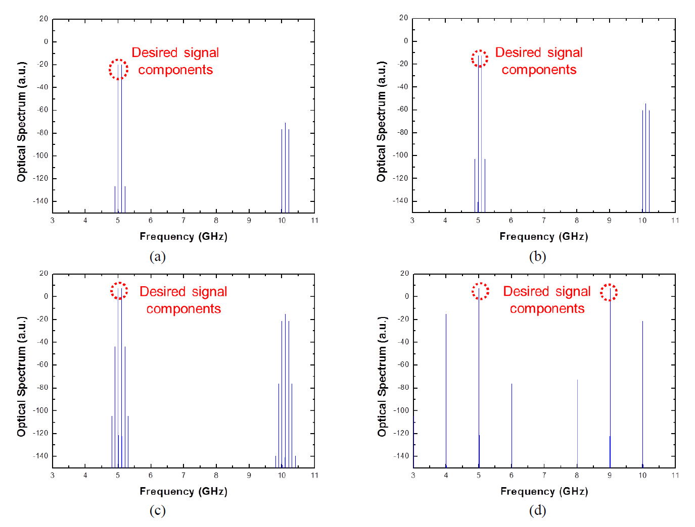
We derived the nonlinear phase shift due to linear and nonlinear fiber characteristics to study the degrading effect of fiber nonlinearity on the SPM-induced power gain [8, 9] in multi-channel SCM systems. For the same transmission distance, the SPM-induced power gain can be generated because the detected RF carrier power with the SPM effect is larger than that of the transmission link with the fiber dispersion effect only. However, the SPM-induced power gain can be degraded because the nonlinear phase shift induced by the SPM effect also generates intermodulation products in the frequency domain. These unwanted components can be increased for larger fiber launching power,and they weaken the subcarrier signal power by beating with generated intermodulation terms. Therefore, the effect of nonlinear phase shift needs to be evaluated by calculating the optical spectra in order to verify the origin of degradation of the SPM-induced power gain in SCM signals.
For a single SCM channel, the nonlinear phase shift induced by SPM at a propagation distance z and normalized time in a frame moving at the group velocity,
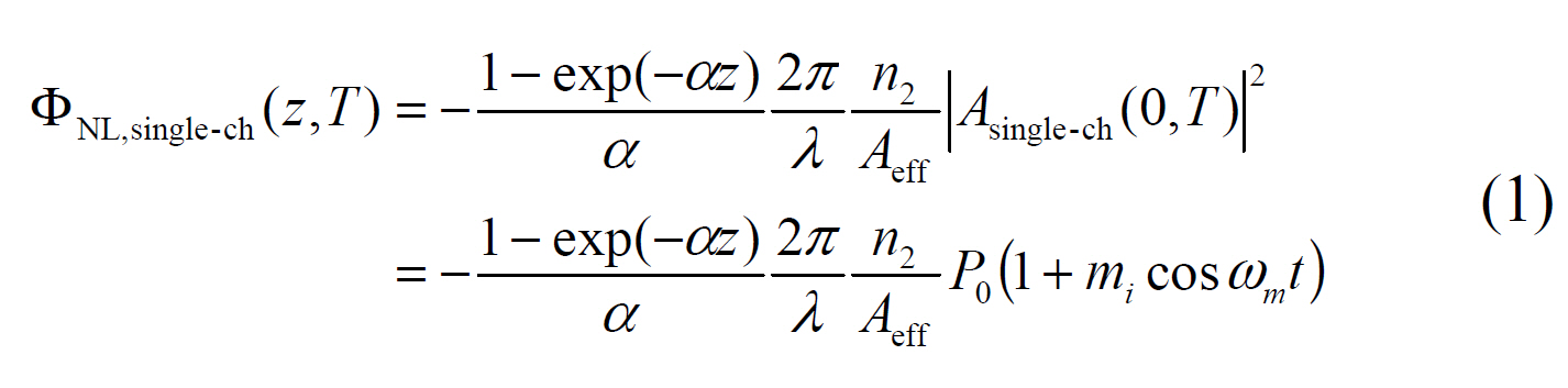
with the field envelope at the fiber input,
where
For multi-channel cases, the initial pulse envelope and the nonlinear phase shift induced by the SPM effect for the two-channel SCM signal can be given by

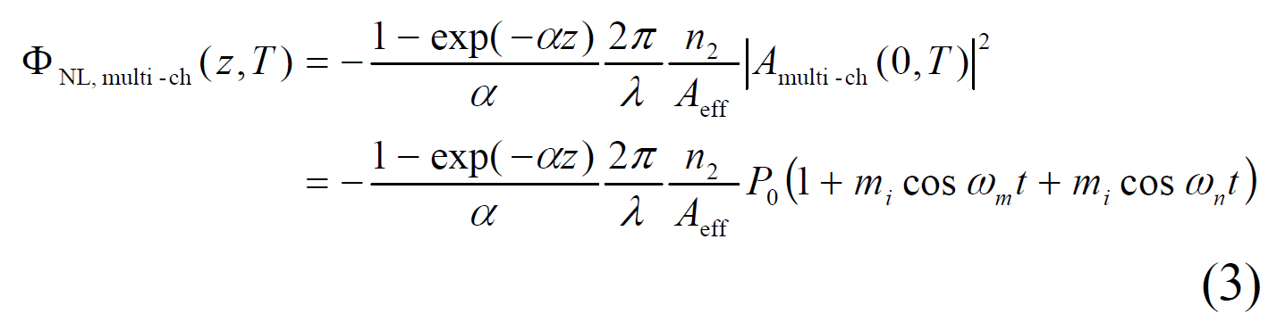
where
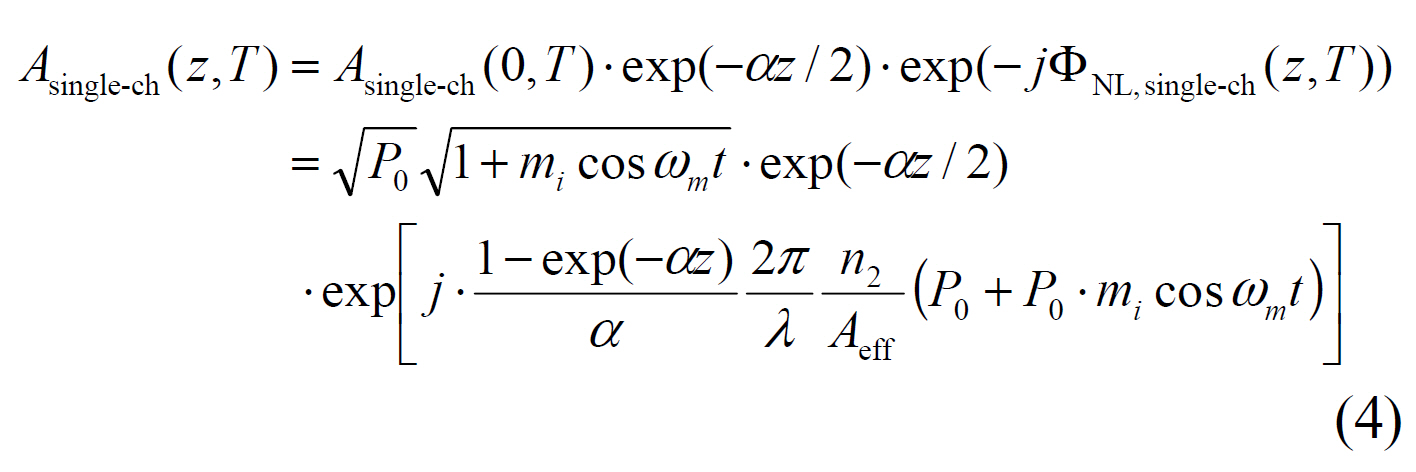
The field of SCM signals with two RF subcarrier channels,considering the initial pulse envelope and phase shift due to SPM, can be given by
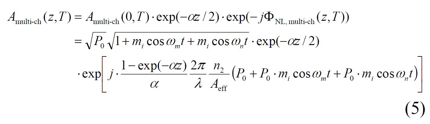
The last term in Eq. (4) indicates the phase shift caused by SPM, and this SPM-induced frequency chirp can compensate for the chromatic dispersion effect in SMF[8,9]. For a two-channel SCM signal, the additional phase shift by SCM frequency
We calculated the optical spectra for various SCM system parameters in order to verify the effect of the optical power
Fig. 1(a) shows the calculated optical spectrum for a two-channel SCM signal (
III. SIMULATION SETUP FOR TWO-CHANNEL SCM TRANSMISSION SYSTEM
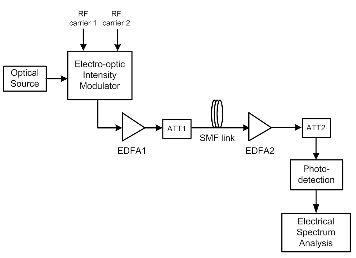
We constructed a simulation setup with a single- or two-channel SCM system by using an optical intensity modulator operating in a linear fashion to observe the effect of fiber transmission link only. Fig. 2 illustrates the block diagram of our simulation configuration to calculate the RF carrier power of the detected SCM signals. The wavelength of the laser diode was 1550 nm, and the input
electrical RF subcarrier signals were pure sinusoidal signals.For optical signal propagation in nonlinear, dispersive, and lossy single-mode fibers, the evolution of a slowly varying electric field pulse envelope can be obtained from the nonlinear Schrodinger equation. The nonlinear Schrodinger equation is a nonlinear partial differential equation that is not generally suited to analytic solutions. This equation was solved via the split-step Fourier method (SSFM) [14].We performed numerical simulations to investigate the combined effect of fiber dispersion and SPM [14-16] on single- and two-channel SCM signals. The fiber launching power entering an SMF was adjusted from 0 to 10 dBm by the first EDFA and optical attenuator before transmission to simultaneously confirm the fiber nonlinear effect.The length of SMF was changed from 0 km to 150 km to apply a different amount of the fiber dispersion effect. The amplitude loss was compensated for via the second EDFA after transmission over SMF, and the second optical attenuator was used to make the optical power received equal to the value of transmitted optical power right after the optical modulator. To calculate the detected RF carrier power of each SCM channel, we used the electrical power spectra calculated after photo-detection. The other specific parameters of the optical SCM transmission links used in the numerical simulations are presented in Table 1. The detected RF power and degradation of SPM-induced power gain were investigated as a measure of the system performance for this simulation environment.
IV. SIMULATION RESULTS AND DISCUSSIONS
4.1. Detected RF Carrier Power
We first constructed a two-channel SCM system with two subcarrier frequencies at 5 GHz and 9 GHz, and we investigated the combined effect of fiber dispersion and
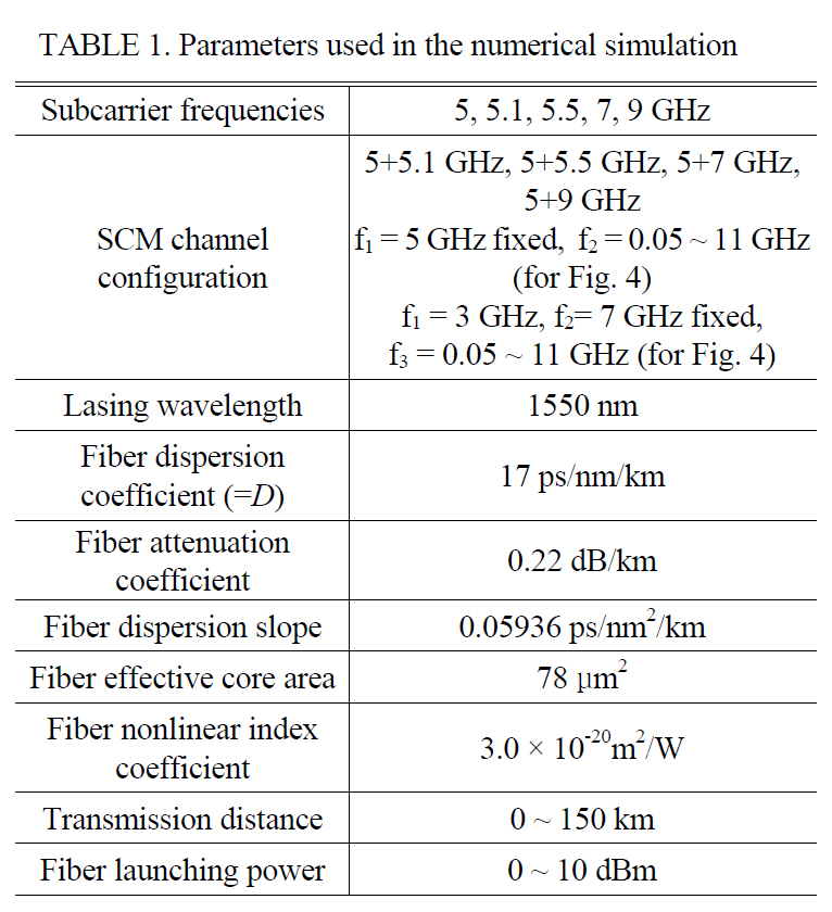
[TABLE 1.] Parameters used in the numerical simulation

Parameters used in the numerical simulation
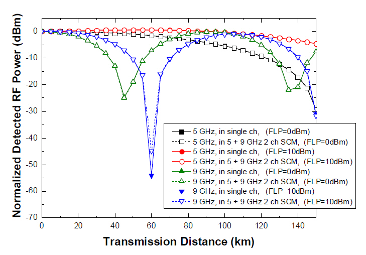
SPM with sufficiently large SCM channel spacing at the beginning. The value of OMI per channel was set to 20%, and the RF carrier power for each detected SCM channel was calculated after transmission over an SMF up to 150 km. We also calculated the detected RF carrier power for a single-carrier transmission system for comparison with the results from the two-channel SCM environments. Fig.3 shows the normalized detected RF carrier power versus transmission distance for the single and two-channel SCM signals. The first null point of the RF carrier power fading curves appeared earlier for the 9 GHz signals because of the DIPP characteristic of the fiber link [7]. The transmission distance at the same detected RF carrier power was extended for both 5 GHz and 9 GHz signals when the high fiber launching power of 10 dBm was applied to the systems, compared to the results obtained from the low fiber launching power of 0 dBm. This is because of the chirping effect of SPM combined with fiber dispersion that brings a dispersion compensation operation in the fiber link [8, 9].
However, the calculated RF carrier power fading characteristics for the single- and two-channel SCM signals appeared almost similarly at different subcarrier frequencies and fiber launching powers. This is due to the fact that there is little effect of the interactions between the subcarrier signals at relatively small value of OMI per channel (= 20%) and large SCM channel spacing (= 4 GHz), as we already showed in Fig. 1. Therefore, the SCM system can preserve the RF carrier power with the two-channel configuration as in the single channel cases. The SPM-induced fiber dispersion compensation effect can be observed to occur independently between subcarriers especially for small OMI per channel and large SCM channel spacing [13].
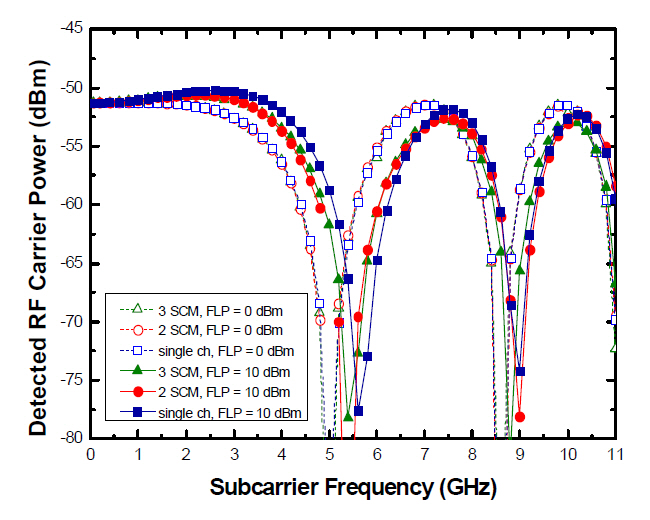
Fig. 4 shows the normalized detected RF carrier power versus different subcarrier frequencies for the single-channel,two-channel, and three-channel SCM signals. For the two-channel system, the frequency of channel 1 was fixed at 5 GHz, and the frequency of channel 2 was varied from 0.05 to 11 GHz. The result from channel 2 at 5 GHz was omitted because it overlapped with the frequency of channel 1. For the three-channel system, the frequency of channel 1 and channel 2 were fixed at 3 GHz, 5 GHz,respectively, and the frequency of channel 3 was varied from 0.05 to 11 GHz. The results from channel 3 at 3 GHz and 7 GHz were also omitted because they overlapped with the frequencies of channel 1 and channel 2. When the fiber launching power was set to be 0 dBm, the detected RF carrier power fading curves of the single-channel, two-channel,and three-channel SCM systems were almost the same.The dispersion induced RF power penalty is sharply reduced by increasing the fiber launching power up to 10 dBm for both the single-channel, two-channel, and threechannel cases. However, the dispersion induced power penalty is degraded for the two-channel cases around the frequency of 5 GHz. For the three-channel case, the dispersion induced power penalty is also degraded around the frequency of 3 GHz and 7 GHz. The amount of degradation around 5 GHz is less than that of the two-channel case because there is no subcarrier at 5 GHz for the three-channel case. These results are also due to the fact that the effect of interactions between the sub-carriers increased for small SCM channel spacing. Although we used the transmission length of 150 km in the numerical simulation results in Fig. 4, we also confirmed similar results for the single channel case after 100 km SMF transmission as the measured fiber responses [9].
4.2. Degradation of SPM-induced Power Gain Due to the Interactions of the Subcarrier Signals
We evaluated the transmission performances of SCM systems in terms of the SPM-induced power gain and the amount of its degradation. For measuring the SPM-induced power gain, we first need to define the transmission distance at P3dB, which is the value of the transmission distance that the detected RF carrier power dropped by 3 dB, compared to that of the back-to-back transmission case.
We calculated the power gain caused by the SPM effect using the detected RF carrier power. The power gain was calculated by the following procedure; first, the detected RF carrier power was calculated at each transmission distance at P3dB. In this case, the effects of fiber dispersion and SPM were considered simultaneously in SCM transmission links. Second, the RF carrier power was calculated again with the effect of fiber dispersion only in the SMF link.As a final step, the power gain due to the SPM effect was quantified by calculating the difference of the detected RF carrier powers between the first and second cases. The SPM-induced power gain was degraded when the multiple SCM channels were applied to the transmission links. We performed the numerical simulations using two-channel SCM signals to accurately investigate and understand the origin of their interactions because it is difficult to determine the origin of these effects in multi-channel environments.
Generally, the amount of SPM-induced power gain in the two-channel system is less than that in the single channel transmission system due to the intermodulation generated by the interactions between sub-carrier components, as we described in Section II. Therefore, the degradation factor for the SPM-induced power gain due to multi-channel configuration can be described as the difference of the SPMinduced power gain of the SCM signal at a certain frequency from the single channel and two-channel cases.
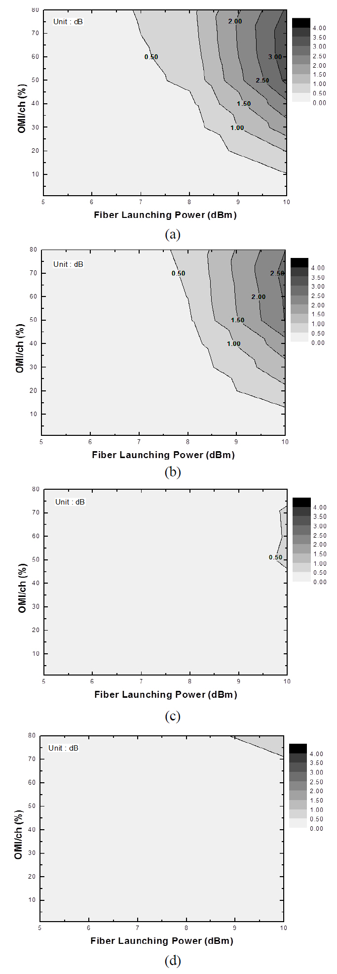
Fiber launching power, OMI per channel, and SCM channel spacing are the important parameters for evaluating the transmission performances of SCM systems. We tried to find the effect of these critical parameters on the SPM-induced power gain in the presence of fiber dispersion and SPM at the same time. The applied OMI per channel and fiber launching power were changed from 0.01 to 80% and from 5 to 10 dBm, respectively. The calculated degradation factors of SPM-induced power gain are shown in Fig. 5 and Fig. 6 as contour plots.
Fig. 5 shows the contour plots of the power gain degradation for the first SCM channel at the second channels at (a) 5.1 GHz, (b) 5.5 GHz, (c) 7 GHz, and (d)9 GHz. Up to the fiber launching power of 5 dBm, there is no significant degradation in the SPM-induced power gain because the effect of fiber nonlinearity is relatively small for low fiber launching power. The general tendency of the calculated power gain degradation factor is proportional to the fiber launching power and OMI per channel. Therefore, the highest degradation occurred at high fiber launching power and large OMI per channel. In Fig. 5(a), a degradation of 2 dB was observed with the fiber launching power of 9 dBm and OMI per channel of 50%. The amount of degradation became over 3.5 dB after increasing the fiber launching power and OMI per channel up to 10 dBm and 80%, respectively. Fig. 5(b) and Fig.5(c) also showed similar power-gain degradation factors with the second channels at the frequencies of 5.5 GHz and 7 GHz, respectively. However, the calculated power gain degradation is significantly decreased when the SCM channel spacing is 4 GHz, i.e., the second channel presents at 9 GHz. This is because the interaction between subcarrier signals is reduced by large SCM channel spacing, resulting in reduced intermodulation terms in the frequency domain.
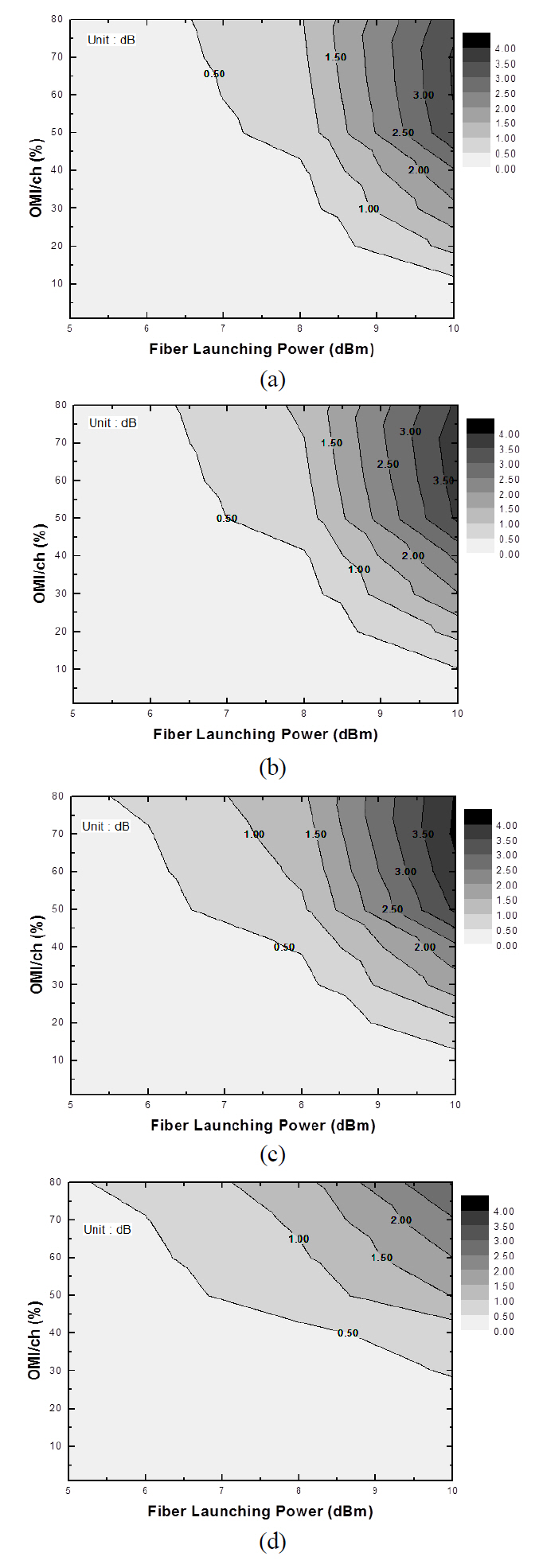
Fig. 6 shows the contour plots of the power gain degradation for the second SCM channels at (a) 5.1 GHz,(b) 5.5 GHz, (c) 7 GHz, and (d) 9 GHz with the first SCM channel fixed at 5 GHz. We obtained similar results in Fig. 5. However, the amount of degradation of SPMinduced power gain is continuously decreased by increasing the SCM channel spacing from 100 MHz (5+5.1 GHz, in Fig. 6(a)) to 4 GHz (5+9 GHz, in Fig 6(d)). Analogous to the results in Fig. 5, large SCM channel spacing can mitigate the generation of intermodulation products caused by interaction between the subcarrier signals. Therefore, in Fig. 6(c) and Fig. 6(d), the amount of degradation is smaller than 1 dB for all possible combinations of the fiber launching power and applied OMI per channel.
From the analysis in Sections II and IV, we can deduce that the power gain due to the SPM effect is degraded at high fiber launching power and large OMI per channel due to the increased intermodulation products, which are generated by the combined effect of the fiber dispersion and SPM when the SCM signal has large OMI values per channel and they allocated within narrow SCM channel spacing. The theoretically calculated optical spectra in Fig.1 also support this phenomenon. The numerical simulation results of power gain degradation can suggest the condition of the input signals to prevent the SCM transmission system suffering from interaction between the subcarrier signals due to the severe nonlinear impairments of the
fiber channel, such as SPM. For example, in the worst case system scenario, i.e., the smallest SCM channel spacing(5+5.1 GHz), the OMI per channel has to be applied by less than 10% with a fiber launching power of 10 dBm to achieve a power gain degradation lower than 0.5 dB, and the OMI has to be lower than 50% with fiber launching power of 8.4 dBm to achieve a power gain degradation lower than 1 dB in detected RF carrier signals. The maximum value of degradation was found to be over 3 dB for the fiber launching power of 10 dBm and OMI per channel of 80%.
We investigated the performance of the multi-channel optical SCM systems with respect to the detected RF carrier power and SPM-induced power gain due to the combined effect of fiber dispersion and SPM via numerical simulations. We also derived the nonlinear phase shift due to linear and nonlinear fiber characteristics to explain these results. The contour plots of the calculated degradation of SPM-induced power gain showed the worst performance in the region with high fiber launching power and large OMI per channel especially for the SCM systems with small channel spacing. The numerical simulation results suggested that the OMI per channel has to be smaller than 10% for the fiber launching power of 10 dBm to guarantee a power gain degradation that is lower than 0.5 dB for the SCM system with a channel spacing of 100 MHz. The results of our work can be utilized to optimize optical transmission systems using the SCM technology in future RoF networks,such as wireless metropolitan area network (MAN) signal distribution via optical fiber networks. From the analyses of SPM-induced power gain degradation, we can predict a proper range of input signal to mitigate the impairment factor caused by the combined effect of fiber dispersion and SPM.