In recent years, the maneuverability and survivability of aircraft against air-to-air missiles during closed-in-combat scenarios has grown. For air-to-air missile systems, an agile turn capability is recommended to effectively shoot down an enemy's aircraft. To improve the missile's maneuverability and achieve agile turn capability, a so called high angleof-attack (AOA) maneuver is required. When the missile is operating at high AOA regions, aerodynamic nonlinearity and uncertainty can be a problem. Accordingly, an autopilot with robustness and a fast response is needed. As a remedy to this,some previous works have been carried out as follows.
Agile missile autopilots have been designed based on the classical control approach with gain-scheduling method(Ryu et al., 2010; Wise and Broy, 1998). In Mehrabian’s work,(Mehrabian and Roshanian, 2006) a linear parameter varying scheme has been applied to the missile autopilot design. A pitch controller with aerodynamic fin and side thrust has also been designed by using dynamic inversion and the extendedmean assignment by Choi et al. (2003). As shown by Menon and Yousefpor (1996), the authors proposed the autopilot design method by combining the feedback linearization technique and linear control theory. The sliding mode control has been also applied to the autopilot problem for agile missile design by Thukral and Innocenti (1998). In the work of Kim et al. (2010), adaptive backstepping methodology has been used for pitch autopilot design. Theorists have also devised sliding mode controllers and time delay controllers in longitudinal missile motion to facilitate agile turn (Kim et al., 2010; Lee et al., 2009c).
In this paper, the authors build on previous works as discussed above (Lee et al., 2009b, c). The AOA is adopted for an appropriate autopilot command structure to achieve a fast response. Then, the robust pitch autopilot is designed based on the time delay control (TDC) methodology (Youcef-Toumi and Wu, 1991). The advantage of the TDC approach is that if an input gain is partially known, a controller can be designed even though the plant dynamics are unknown. For this reason, the TDC can be applicable in the case of agile turn under the presence of model uncertainties. To design an autopilot, we should derive the approximated aerodynamic model, which is given by a polynomial function of AOA, from the experimental aerodynamic data. Next, the input-output linearization technique is used to attain an appropriate form of dynamics for the AOA controller. By using this equation that represents an explicit relationship between tracking state and input, we apply the TDC scheme to pitch autopilot design. In order to implement the proposed AOA controller,feedback of AOA information is needed. Unlike normal acceleration, it is hard to measure the AOA in flight. Instead,since the AOA is directly related to the normal acceleration and the pitch rate, we construct a nonlinear observer in order to estimate AOA that uses the normal acceleration and the pitch rate measurement. Finally, we develop the autopilot design scheme by combining the robust AOA controller and the nonlinear observer.
This article is composed of four sections. In Section 2, the missile model used in the autopilot design is discussed. The proposed autopilot design method is provided in Section 3.To show the validity of the proposed controller, numerical simulations are performed and its results are given in Section 4. Finally, conclusions of this study are offered in Section 5.
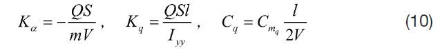
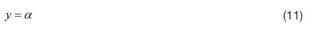
In this section, the nonlinear missile model considered hereafter is explained. The missile motion can be decoupled into two perpendicular channels in the skid-to-turn cruciform type missile. A longitudinal motion with a high AOA capability is considered. Under the assumption that the missile has rigid body dynamics and the gravity force is ignored, the missile dynamics including the first-order actuator dynamics can be expressed as:
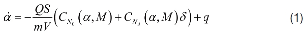
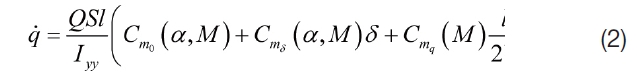
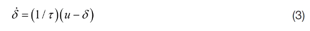
where the notation of α, q and δ describe AOA, pitch rate and fin deflection angle, respectively. The missile velocity,mass, moment of inertia with respect to pitch axis, dynamic pressure, reference area, and reference length are expressed by V, m, Iyy, Q, S and l, respectively. τ represents time constant of the actuator and M is the Mach number.
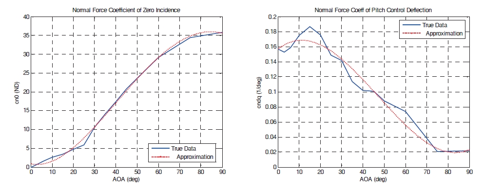
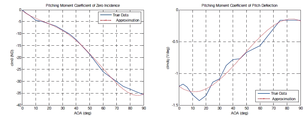
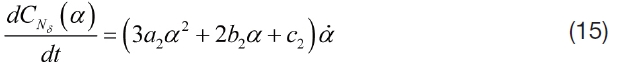
In Eqs. (1) and (2), the missile dynamics include the aerodynamic coefficients, CN0, CNδ, Cm0, Cmδ, Cmq, which are dependent upon the variation of AOA, Mach number, and fin deflection. In general, these parameters are not directly given by the function of AOA, Mach number, and fin deflection.Instead, these are computed by interpolation of experimental data tables. For controller design purposes, the aerodynamic coefficients must be given by a function form. As shown in Figs. 1 and 2, for a fixed Mach number, these parameters can be represented as 3rd and 4th order polynomial functions of AOA. Accordingly, under Mach number
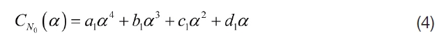
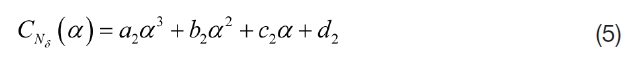
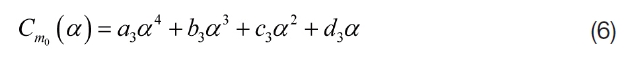
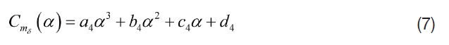
where
where
In this section, we discuss the missile autopilot design based on the TDC with nonlinear observer (Youcef-Toumi and Wu, 1991). The proposed controller configuration is shown in Fig. 3 In order to design the AOA controller, we first derive the dynamics which represent an explicit relationship between
Fig. 3 The configuration of the proposed control method.
3.1 Input-output linearization
In order to derive an appropriate equation for applying the TDC, the input-output linearization technique (Slotine and Li, 1991) is first applied to the above missile model as given in Eqs.(1) through (3). For the control objective, we choose AOA as the output state. The output is not directly related to control input in the missile model so that we take a timederivative of output to find the direct relationship between the system output y and control input
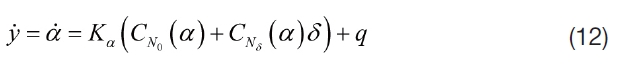
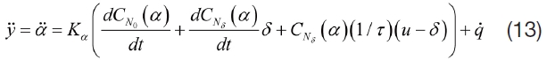
At the second derivative of AOA, control input
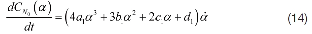
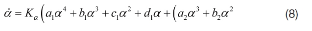
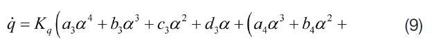
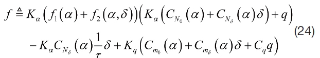
For simplicity's sake, let the new functions be defined as:
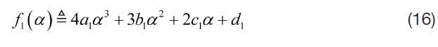
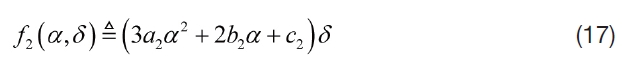
Substituting Eqs.(14) through (17) into Eq.(13), the second time-derivative of AOA can be rewritten as:
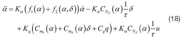
Equation (18) represents an explicit relationship between
Theorem 1. When angle of attack is chosen for output state in input-output linearization of the system as given in Eq.(1)through (3), the internal dynamics is stable.
Proof . From Eq. (18), the control input can be formulated as:
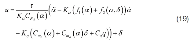
To obtain the internal dynamics, we substitute the obtained control input as shown in Eq.(19) into Eq.(3). Then,we get the internal dynamic as below:
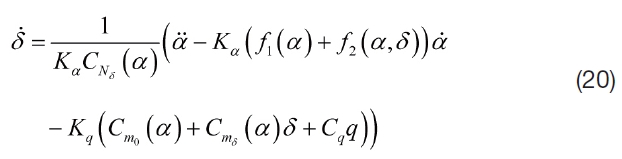
It is noted that the internal dynamic is considerably complicated to check its stability. Subsequently, we indirectly consider the zero dynamic instead of the internal dynamics.The zero dynamics is given by the internal dynamics when the output is kept at zero by the control input as α = α?= α¨ =0.Applying this condition to the internal dynamics, we have the following zero dynamics as:

where C1 and C2 are defined as:
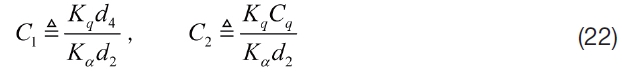
According to approximated aerodynamic coefficients, C1 and C2 are given by positive values. In addition, d2 is positive and Kα is negative. Consequently, C3 is a positive value. From Eq.(21), it can be easily shown that the zero dynamics is asymptotically stable.
3.2 Time delay controller design
The dynamics of AOA as shown in Eq. (18) can be rewritten in a simplified form,

where
To design the AOA controller based on the TDC, Eq. (23)is reformulated as:
In this equation, it is assumed that the dynamics
where the unknown term
Next, we construct the control input
where
where ed=Δαc-α, which denotes tracking error between command and response. Substituting Eq. (29) and (30) into Eq. (27), the error dynamics can be obtained as:
where
Substituting Eq. (32) into Eq. (29), we finally have the TDC law as follows:
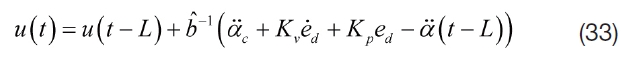
According to Eq. (33), it is noted that the control law does not require the plant model. However, to estimate an unknown term, the previous control input and the second derivative of AOA measurement are additionally needed.
In order to implement the proposed controller as given in Eq. (33), the AOA measurements are required, but it is difficult to obtain those measurements from conventional devices. Accordingly, in this paper, the authors propose a nonlinear observer to estimate AOA as studied suggested by Devaud et al. (1998). In their work, the nonlinear observer was designed based on the known plant model, while we assume that the model of the nonlinear observer also has uncertainty. If the model of the nonlinear observer is exactly known, the normal acceleration feedback is enough to estimate AOA information. Conversely, we use the normal acceleration feedback and the pitch rate to improve the performance of the nonlinear observer against the model uncertainty as follows:
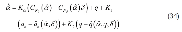

where an and q? denote the estimation of normal acceleration and the estimation of pitch rate, respectively. an and q? can be determined as:

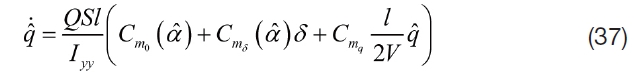
where
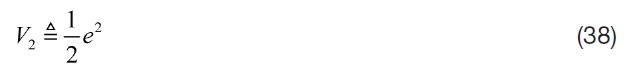
Taking the time-derivative of
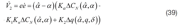
where:
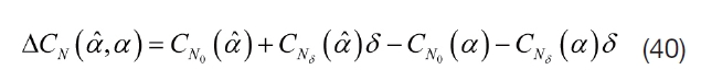
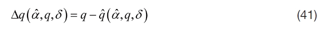
To make V˙2 < 0 and to ensure the exponential stability of the nonlinear observer, for a positive real number ε and some real number
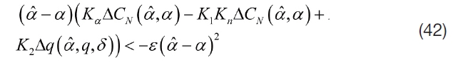
In order to select proper values of
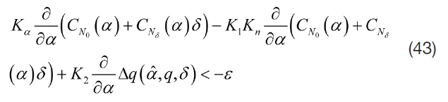
From Eq. (43), the first term of the left-hand side is independent of
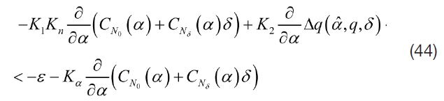
In Eq. (44), it can be easily observed that the value of the left-hand side has two degrees of freedom related to
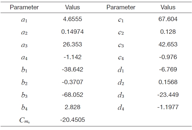
In this section, to investigate the performance of the proposed controller, numerical simulations are carried out in conjunction with the nonlinear observer. The missile model used in simulation is given by the following parameters. The mass and pitch axis moment of inertia are

[Table 1.] Aerodynamic model parameters

Aerodynamic model parameters
We assume that initial estimation of angle-of attack is zero, α? (0) = 0˚. The parameters for AOA estimator are chosen as:

The remainder of this section is concerned with three kinds of nonlinear simulation results. In a high operational AOA range as the agile missile, the aerodynamic parameters could not be obtained accurately. Therefore, to test the robustness of the proposed controller, we consider 30%aerodynamic uncertainties in all simulations. In order to implement the proposed controller, partial information of the plant model is required so that the proposed controller may have robustness against model uncertainties.
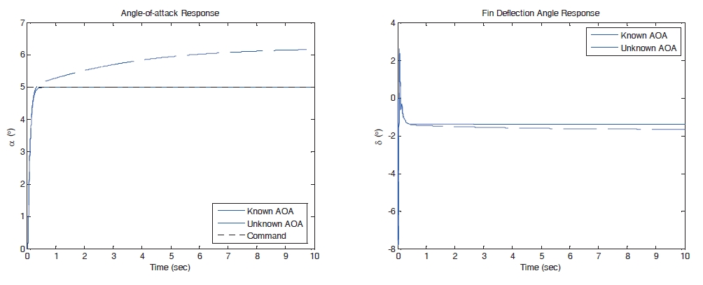
In the first place, the proposed controller with known and unknown AOA measurement is applied to the longitudinal missile model. In the known AOA measurement case, we assume that AOA can be directly measured. In the unknown AOA measurement case, it is assumed that the AOA is estimated from the plant model which contains model uncertainties; it is the same as the estimation of the AOA using the nonlinear observer as shown in Eq. (34) with
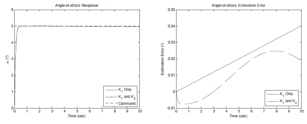
Figure 4 provides the step input response of AOA and control input in cases of known and unknown AOA measurement. If we use the true AOA measurement, the proposed controller has a good tracking performance in spite of the absence of the plant model information and the uncertainty of input gain. When the unknown AOA measurement is applied to the proposed controller, the tracking error increases as shown in Fig. 4 For this reason, we need the nonlinear observer to compensate the tracking error under the absence of the true AOA measurement. Figure 5 provides the AOA response and the estimation error under the proposed controller with the nonlinear observer. Two simulation results as shown in Fig. 5 provide a good tracking performance in the presence of model uncertainties. However, in the nonlinear observer as studied in Devaud et al. (1998), which uses
In this paper, based on the TDC methodology, we discuss the pitch autopilot design for missiles operating at high AOA regions in the presence of aerodynamic nonlinearity and uncertainty. The authors first derive the appropriate nonlinear dynamics for AOA control based on input-output linearization techniques and prove its internal dynamics stability. From the results, the design method of the robust AOA controller against model uncertainty using the time delay estimation techniques is provided. In order to implement the proposed controllers, a nonlinear observer is developed to estimate AOA under model uncertainty.Numerical simulations show that the proposed method can provide a good tracking performance against model uncertainty and can be successfully applied to the agile turn phase of air-to-air missiles.