Advances in the manufacturing process and technology of laminated composites have changed the use of the composites from secondary structural components to the primary ones. In particular, laminated composites are commonly used in aeronautical and aerospace industries as the main part of the structure rather than aluminum or other metallic materials. These recent trends require more accurate static/dynamic analyses of the laminated composites (Cho and Kim JH, 1996a; Cho and Kim JS, 1996b, 1997; Jones, 1975; Park et al., 2009) since the composites have inhomogeneous and anisotropic characteristics. More importantly, laminated composite plates exhibit a larger shear deformation than isotropic plates because the epoxy material used as the matrix of the composites are weak in shear in general. Thus, classical theories, such as Kirchhoff-Love plate theory and Reissner-Mindlin plate theory without shear correction factors are inappropriate for the analysis of laminated composite plates.The improved theories accurately predict the stress fields and represent higher-order deformation fields with low degreesof-freedom. For the last three decades, many refined theories have been developed. These theories can be categorized into three groups: smeared theories, zig-zag theories and layerwise theories (Carrera, 2003; Kapania and Raciti, 1989;Noor and Burton, 1989; Reddy et al., 1994). These higherorder theories, however, are defective because accuracy cannot be guaranteed and they strongly rely on initially assumed warping functions. A method that can obtain the proper warping functions from three-dimensional elasticity is necessary. Among such methods, an asymptotic approach equipped with a rigorous mathematical foundation may be a viable option.
In general, three asymptotic methods exist: the variationalasymptotic method (Berdichevskii, 1979; Berg, 1991),the formal asymptotic method (Niordson, 1979), and the asymptotic integration method (Novotny, 1970; Wang and Tarn, 1994). Yu et al. (2002) and Yu (2005) used the variational asymptotic method to derive a Reissner-Mindlin-like plate theory using through-the-thickness finite element analysis.Meanwhile, the decay method or the averaged boundary conditions were used to determine the interior solution for displacement prescribed boundaries (Buannic and Cartraud,2001; Duva and Simmonds, 1992; Kim, 2009; Kim et al.,2008). The generalized averaged boundary conditions were successively employed to generic anisotropic beams, which demand much less efforts than the decay analysis method.Kim and Wang (2010) also performed a vibration analysis of composite beams based on the averaged boundary conditions. The results obtained therein were promising and provided physical insight on the three-dimensional behavior of plates. Furthermore, this analysis prompted researchers to consider the three-dimensional composite coupling characteristics accurately. Recently, Kim (2009) developed the formal asymptotic method-based plate analysis, called the FAMPA, while accounting for the averaged boundary conditions. The solutions calculated were accurate in both simply-supported and clamped boundary conditions with reasonable computational efforts. However, the previous studies were only carried out for the semi-infinite plates in which the two-dimensional effects, such as the mechanical coupling induced by different layup configurations, were ignored. Thus, the two-dimensional rectangular composite plates must be analyzed in order to account for the composite coupling effects to the macroscopic structural behavior.
In this paper, the authors follow Kim’s work (2009) and obtain an analytical asymptotic solution for rectangular composite plates under doubly sinusoidal loading. To validate the present approach for various rectangular plates, the asymptotic solutions obtained at each level were compared to the solutions of the classical laminated plate theory (CLPT), the first-order shear deformation theory(FSDT), and three-dimensional elasticity. The process by which the asymptotic solution approached the exact solution qualitatively was also discussed for the given examples.
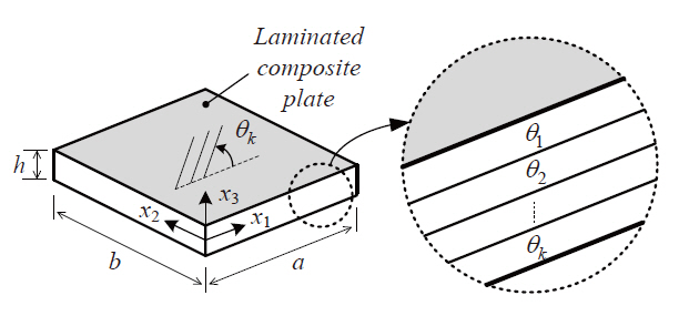
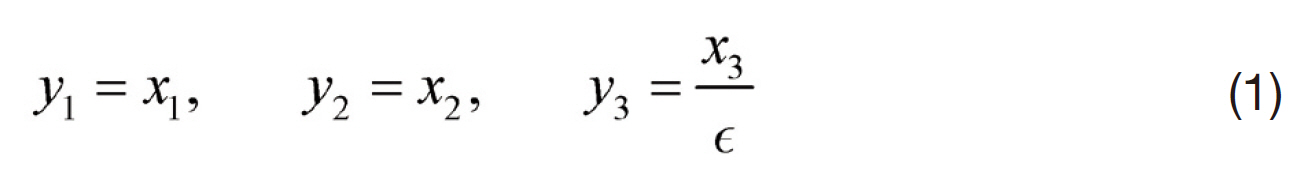
A three-dimensional heterogeneous plate composed of composite materials is shown in Fig. 1. For the application of an asymptotic expansion method, a small parameter (o)is defined as the ratio of the characteristic length (or wave length) to the height of the plate, and the coordinates are scaled in the following manner.
where a small parameter is defined by ∫ =
The governing equations for three-dimensional linear elastostatic problems can be expressed by substituting Eq.(1) into the equilibrium equations, strain-displacement relationships, and constitutive equations as follows:
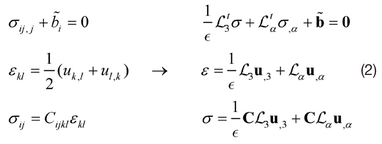
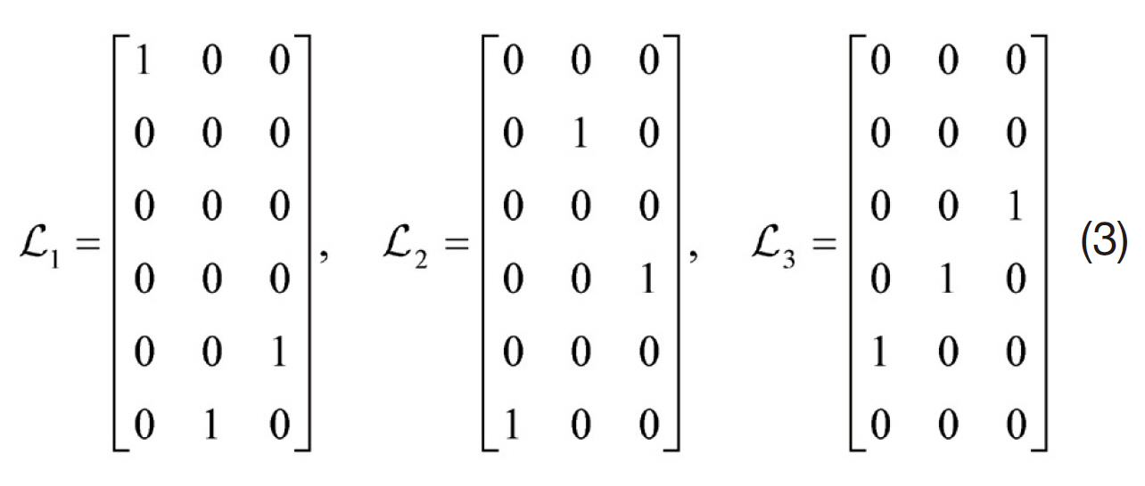
where the linear operators Li are defined by
In the scaled equations in Eq. (2), ( ),i indicates the partial derivative with respect to the coordinate yi, ‘
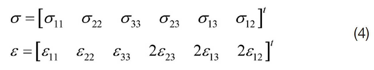
The stress and strain tensors are expressed in the vector form as
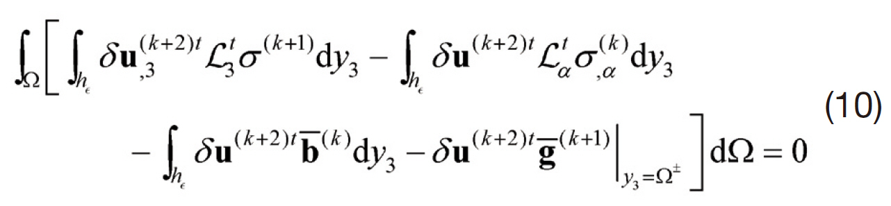
The associated boundary conditions are given by
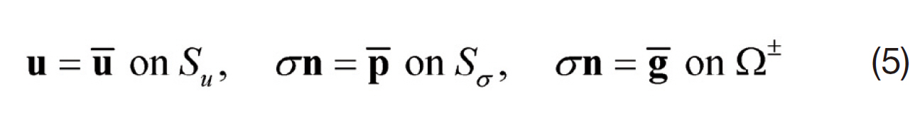
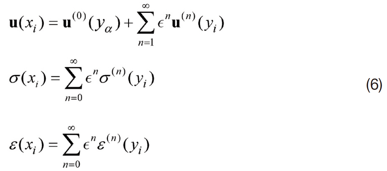
where p? and g? represent the prescribed traction and the body force, respectively. The displacement is asymptotically expanded in terms of the small parameter (∫). Subsequently substituting the expanded displacement into the stress and strain expressions given in Eq. (2) yields the displacement,stress and strain expansions as follows:
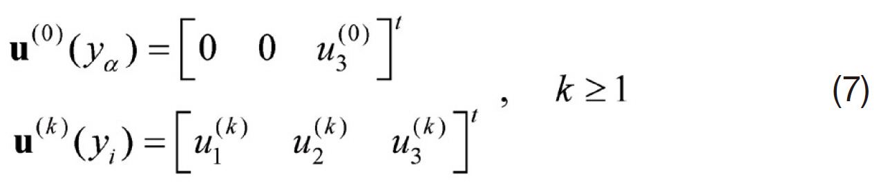
Because of the asymptotic convergence (Kim, 2009; Kim et al., 2008), the zeroth order displacements and each order displacements are assumed by
where
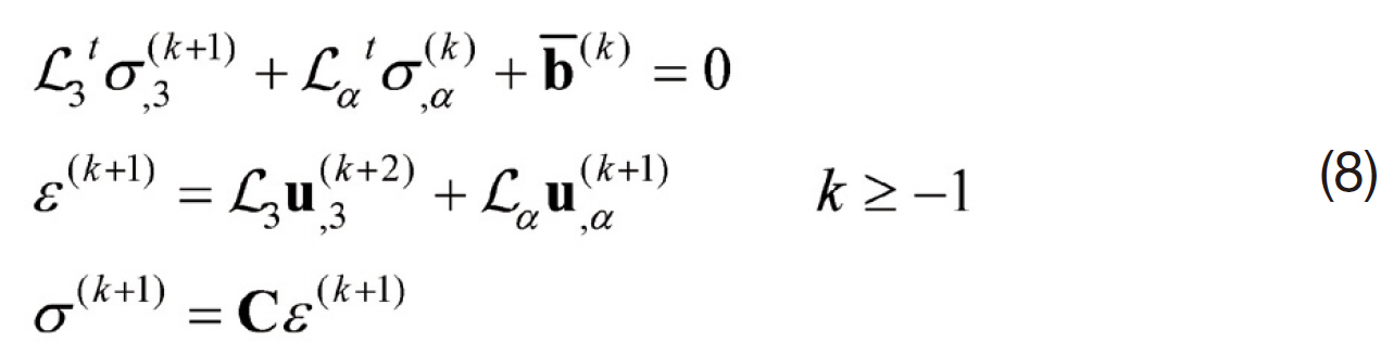
By substituting Eq. (6) into Eqs. (2) and (5) and collecting the same order of the small parameter, thefollowing recursive equations can be obtained:
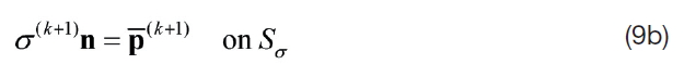
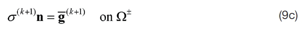
The boundary conditions at the edges and at the top and bottom surfaces of the plate are expressed by

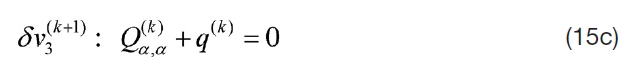
where u?
2.2 Separation of micro-scale and macro-scale
From the first microscopic problem (
where h∫ is the scaled thickness of the plate. The displacement can be decomposed into two terms as

where the first term is the fundamental solution and the second is the warping solution. Substituting Eq. (11) into Eq.(10) gives two equations corresponding to δu~(
The microscopic solution can be obtained using throughthe-thickness analysis. By introducing the one-dimensional finite element discretization, the warping solution of each order can be calculated. The warping solution is then obtained by employing the one-dimensional Lagrangian interpolation function. That is
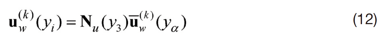
Consequently the warping solutions are generalized by
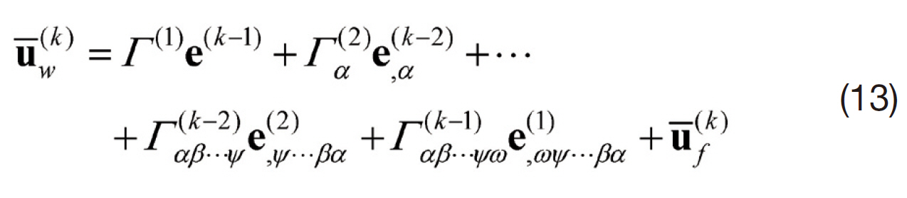
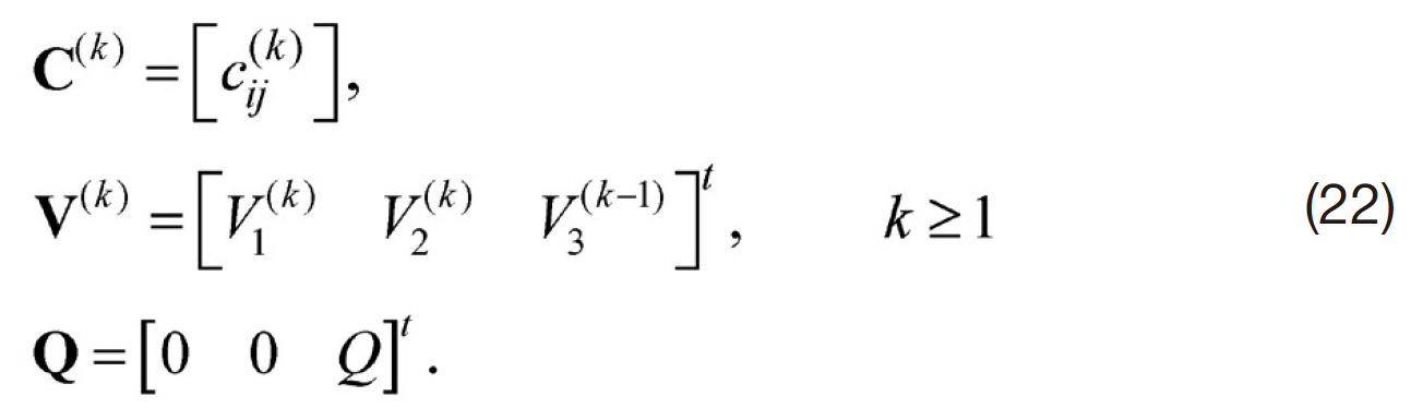
where the macroscopic strain e(k), the displacement due to the body force and traction u?f(k), and the warping distribution Γ(m) are represented as follows:
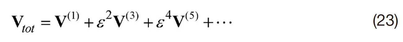
The macroscopic equilibrium equations can be derived from the macroscopic problems obtained in Eq. (10). Thus,the macroscopic equilibrium equations are obtained by
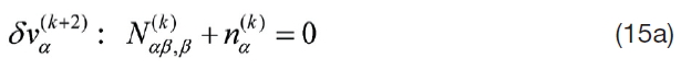
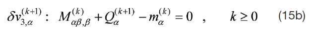
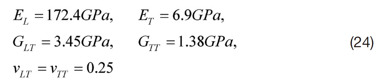
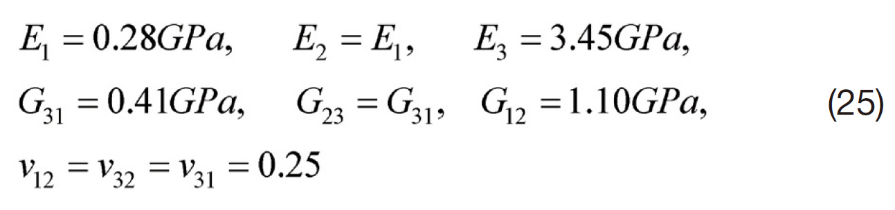
where
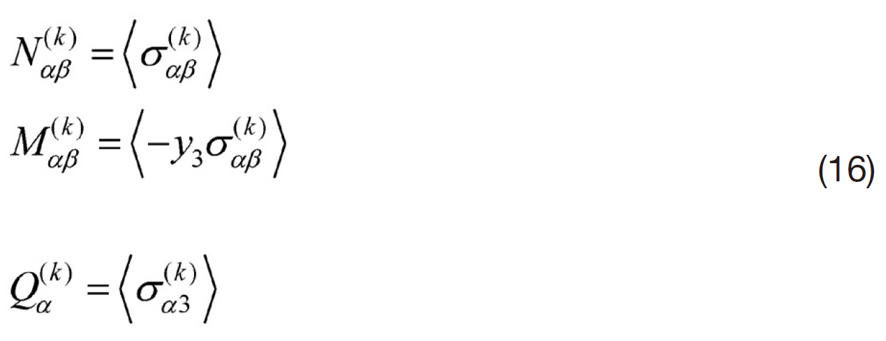
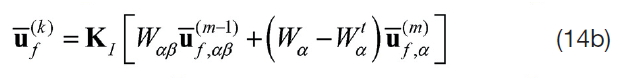
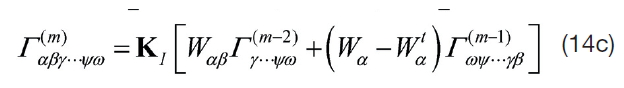
in which
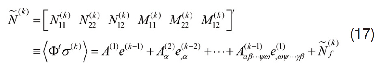
The detailed definitions of matrices used in Eqs. (14-17)are omitted for the sake of brevity, but can be found in Kim’s studies (2009).
In the present study, the analytical solution (Navier solution) of composite plates was calculated under doubly sinusoidal loading. Thus, the transverse load considered the order of magnitude is expressed as follows:
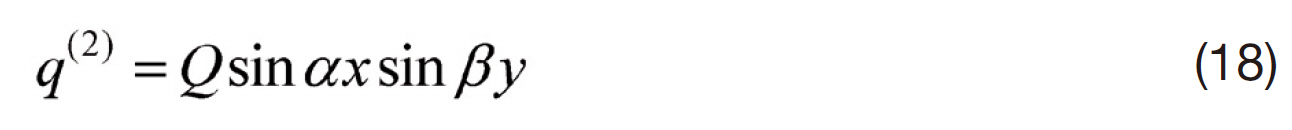
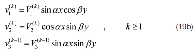
where α = π/a, β = π/b, and Q is constant. The displacements of the plate were assumed by accounting for the layup configuration of the composite. The boundary conditions of each layup are described in Reddy’s work (2004). The displacement fields for the cross-ply and anti-symmetric angle ply laminates are given as follows:
Cross-ply case
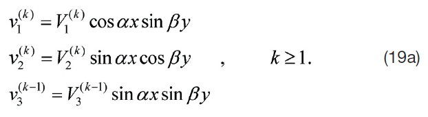
Angle-ply case (anti-symmetric)
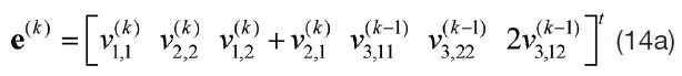
By substituting the assumed displacement fields into Eq.(14a) and solving Eq. (15), the coefficients of the displacement fields can be obtained. When k = 1 (zeroth order solution),the equations become

The second, fourth and generalized equations can be derived from Eqs. (15) and (17) as follows:
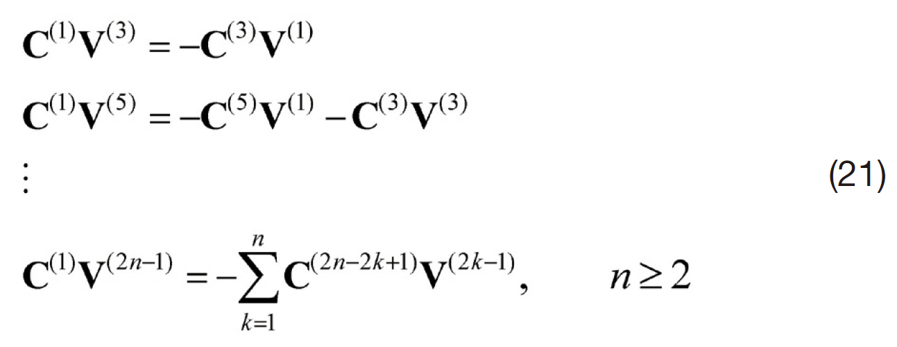
where
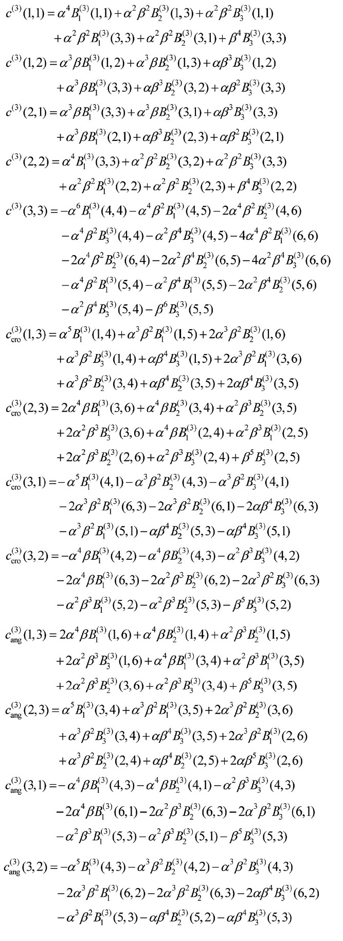
The matrices C(1), C(3) and C(5), which depend on the layup configuration of the laminates, are explicitly listed in Appendix A-1. The coefficients calculated in the previous orders form the part of force vector in the current order linear system equation. Eventually the total displacement coefficient vector takes the form of
4. Numerical Examples and Discussion
In order to verify the present asymptotic analysis, crossply,anti-symmetric angle ply and sandwich plates were studied as illustrative examples. To investigate the effects of the various geometric properties, rectangular (
where
[Table 1.] Layup configuration for laminated and sandwich plates
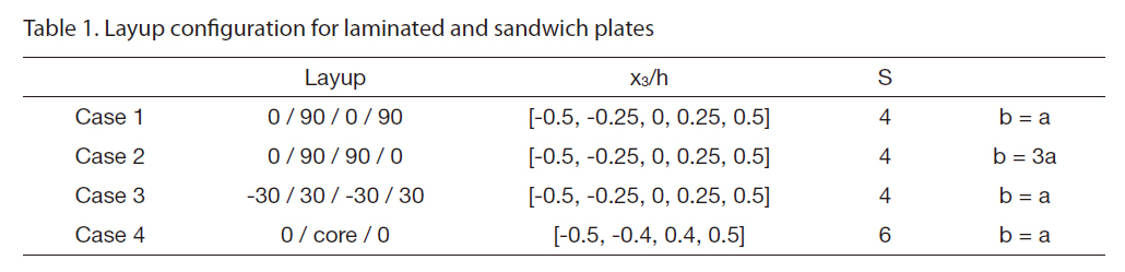
Layup configuration for laminated and sandwich plates
[Table 2.] Maximum deflections of simply supported plates under sinusoidal loads
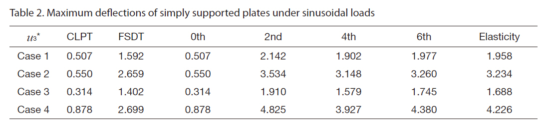
Maximum deflections of simply supported plates under sinusoidal loads
To compare the present results with the CLPT, FSDT and three-dimensional elasticity solution (Pagano, 1970;Savoia and Reddy, 1992), the following non-dimensional parameters are defined:
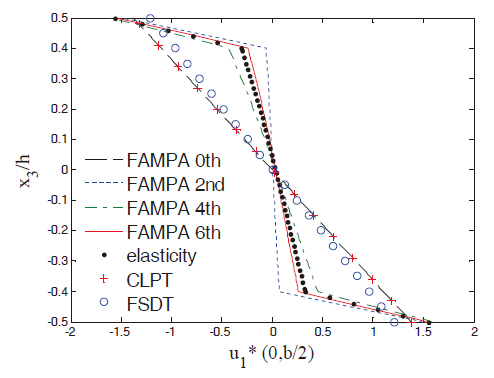
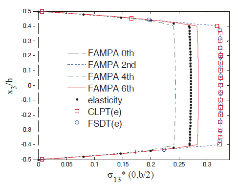
First, the normalized maximum deflections for each case are listed and compared in Table 2. The zeroth-order solution of u3* was the same as the CLPT solution because the present approach performed the recursive analysis based on the CLPT. The shear correction factor was assumed to be 5/6 for the FSDT. The solutions from all four cases obtained by the CLPT and FSDT exhibited large differences compared to the elasticity solution since the plates were extremely thick. The deflections obtained by the FAMPA-2nd were closer to the elasticity solution than those from the FSDT. The difference originated from the assumption applied to the FSDT. The actual shear deformation of the composite laminates was not linear, which held the form of higher-order polynomials and zig-zag functions.
These complicated deformations can be accounted for through the asymptotic expansion method. In previous studies concerning composite beams and semi-infinite composite plates (Kim, 2009; Kim et al.,2008), the very first warping solution represented the threedimensional Poisson’s effect and the second warping solution represented the transverse shear deformation. In other words, it is more general and accurate to predict the elastic behavior of anisotropic plates using the CLPT considering the gradient effects and boundary conditions, which can be obtained by the asymptotic analysis. Another advantage of the present method is that the calculated solutions are located between the upper and lower boundaries of the exact solution. Thus, the approach can be applied to the problems which are difficult to obtain the elasticity solution.
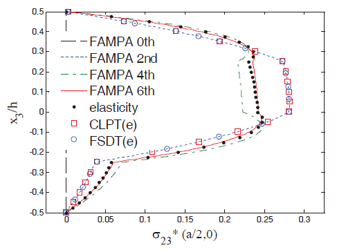
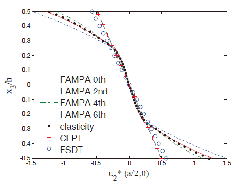
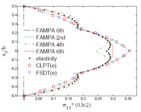
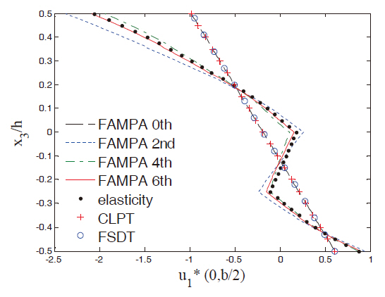
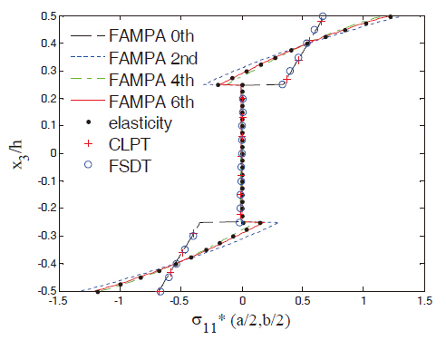
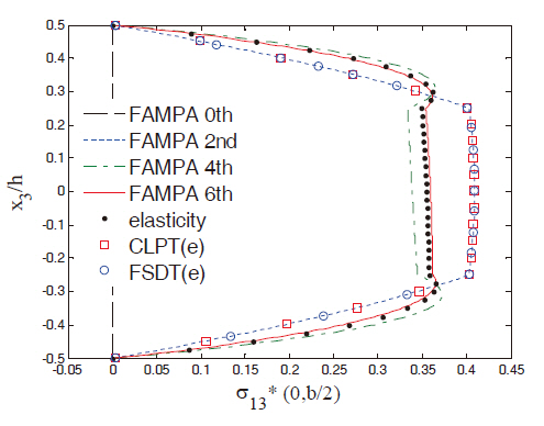
Figures 2 and 3 show the in-plane displacement and transverse shear stress distributions through the thickness of the plate for Case 1. The FAMPA-6th matched well with the elasticity solution, even when the length-to-thickness ratio was very high (S = 4). The through-the-thickness distributions of the FAMPA-2nd were similar to those of the FSDT, which were the same results as the semi-infinite composite plates (Kim,2009). Figures 4 and 5 illustrate the in-plane normal and transverse shear stresses through the thickness for Case 2.The results of the present method were almost identical to the elasticity solutions. In Fig. 4, the difference between the FAMPA-2nd and FAMPA-6th was about 15%, which implies that the failure criteria of σ5 decreased by 15% when the FSDT was used. Even though the plate was relatively thick, this tendency can be problematic during the actual design stage.The through-the-thickness distributions of the displacement and transverse shear stress for Case 3 are presented in Figs. 6 and 7, which show an excellent agreement with the elasticity solutions. As amply demonstrated by the sample results, the present method yielded an efficient yet accurate throughthe-thickness prediction of the displacements and stresses for the composite plates.
The results of the sandwich plate (Case 4) are shown in Figs. 8 and 9. Unlike the previous cases (the laminated composite plates), the length-to-thickness ratio was assumed to be 6, since the significant shear deformation due to the flexible core material slowed down the convergence rate. In the case of transverse shear stresses, the FAMPA-6th for the laminated composite plates agreed well with the elasticity solutions, as was shown in Figs. 3, 5 and 7, whereas the slow convergence for the sandwich plate can be observed in Fig. 9.In fact, convergence failed when the length-to-thickness was less than 5. This implies that there are some criteria for the characteristic length of plates to converge. In other words,a decay condition for the boundary layer effects may exist.This is, however, beyond the scope of the present study. Thus the length-to-thickness ratio (S = 6), which yielded slowly converging results, was investigated. As illustrated in Figs.8 and 9, the convergence was relatively slow in comparison to the involving laminated composite plates. However, one can see that the elasticity solution still existed between the FAMPA-4th and FAMPA-6th. Consequently, by putting the various results together, the convergence rate depended on the layup configuration and the plate geometry, which will be investigated in the future.
The formal asymptotic method-based plate analysis was conducted for various rectangular plates. The analytical solutions obtained under the doubly sinusoidal loading confirmed the accuracy of the present approach. In order to obtain the two-dimensional plate equations, which were formulated with rigorous mathematical foundation, the initial three-dimensional problems were divided into twodimensional macroscopic and one-dimensional microscopic equations. By introducing the one-dimensional throughthe-thickness finite element analysis, the microscopic characteristics were systematically smeared into the macroscopic plate equations. The explicit forms of the twodimensional plate equations were derived and listed up to the third-order. The solutions obtained yielded high fidelity results in comparison to the elasticity solution.
However, the convergence rates for the layup configurations were different from each other. This implies that the characteristic length of the composite was somewhat different from the isotropic case. Although the asymptotic analysis has been widely adopted in the society of mathematical elasticity (Dauge and Gruais, 1996) to investigate the proper boundary condition and convergence of the isotropic plate, the intensive analysis concerning the characteristic length of the composite plates has not been studied yet. This will be the topic of future studies.
Components of the first order matrix C(1), C(3) and C(5).
simplified matrices
C(1) matrix
C(3) matrix
C(5) matrix