Unlike fixed-wing aircrafts, helicopters are exposed to high vibration levels that lead to poor ride quality and reduce the operational life of critical components. The high noise level of helicopters also restricts both military and civil operations. Therefore, reducing the vibration and noise level of helicopters facilitates the designs of more reliable and environmentally friendly helicopters.
One of the main sources of helicopter vibration and noise is unsteady aerodynamic phenomena such as the blade-vortex interaction (BVI) and the mutual aerodynamic interference between those components including the main rotor, fuselage and tail rotor. For modern helicopters requiring higher disk loading and compactness to maximize the maneuverability,the aerodynamic interaction becomes a more critical issue(Leishman, 2006). Therefore, precise understanding of the interactional aerodynamic characteristics between the components and their wake is needed for helicopter design.
Several researchers have previously conducted investigations in order to understand the flow fields around helicopters in which mutual aerodynamic interaction between the main rotor and the fuselage exist. In previous studies, lifting line/free-wake methods coupled with a potential theory were used (Lorber and Egolf, 1990; Mavris et al., 1989; Wachspress et al., 2003). These methods are computationally efficient and provide a fundamental understanding of the rotor-fuselage interaction, but are limited in simulating real flows due to the potential flow assumption. To overcome these limitations, recent studies have utilized computational fluid dynamics (CFD) methods based on the Euler and Navier-Stokes equations. However,most applications of the CFD methods were limited to isolated-rotors (Ananthan et al., 2008; Datta et al., 2006;Potsdam et al., 2004; Yang et al., 2002) and rotor-fuselage configurations (Dietz et al., 2008; Nam et al., 2006; Yang et al., 2008; You et al., 2006). Therefore, important features of the aerodynamic interaction of complete helicopter configurations are still not well understood.
In the present study, the flow fields around complete helicopter configurations were numerically simulated,and the aerodynamic interaction among the main rotor,fuselage, and tail rotor was investigated. For this purpose,a three-dimensional flow solver (Jung et al., 2007) based on unstructured meshes was used. An overset mesh technique was adopted to effectively manage the relative motion of those components. Validation of the flow solver was made for a UH-60A configuration at high-speed and low-speed forward flight conditions by comparing the results with available flight test data and other calculations. Additional calculations were made for a generic complete helicopter configuration at various flight conditions, and their effects on the blade airloads and the wake structure were studied.
The equations governing three-dimensional, inviscid,unsteady, compressible flows are the Euler equations, which can be recast in an integral form for a bounded domain,
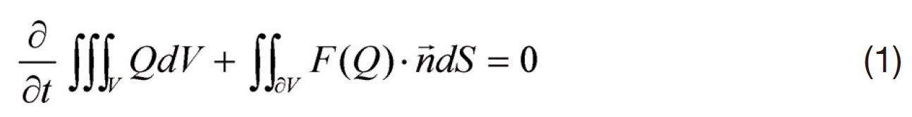
where Q = [ ρ, ρu, ρv, ρw, e0] is the solution vector of the conservative variables for the mass, momentum and energy equations. The governing equations were discretized using a vertex-centered finite-volume method. The flow domain was divided into a finite number of control volumes surrounding each vertex, which are made of a non-overlapping mediandual cell whose boundary surfaces are defined by the cell centroid, face centroid, and mid-point of the edge. The inviscid flux vector term,
An implicit time integration algorithm based on a linearized second-order Euler backward differencing was used to advance the solution in time. The linear system of equations was solved at each time step using a point Gauss-Seidel method.
An unstructured overset mesh technique (Jung and Kwon,2007) was adopted to manage the relative motion between the main rotor, fuselage, and tail rotor. In this overset mesh scheme, the mesh topology was composed of multiple independent mesh blocks. The main background mesh represents the complete computational domain and contains the fuselage, and the sub-block meshes cover each individual blade of the main rotor and the tail rotor. This overset mesh scheme conveniently allowed the treatment of blade motion due to input pitch setting and flapping motion.
To reduce the large computational time, a parallel algorithm based on a domain decomposition strategy was adopted. Load balancing between the processors was achieved by partitioning the global computational domain into local subdomains using the MeTiS libraries.The Message Passing Interface was used to transfer the flow variables across the subdomain boundaries. All calculations were performed on PC-based Linux clusters.
Initially, calculation was made for a complete configuration of UH-60A helicopter in high-speed and low-speed forward flights to validate the capability of the present flow solver.Then, the flow solver was applied to a generic complete helicopter configuration at various operating conditions including forward, backward, and sideward flights.
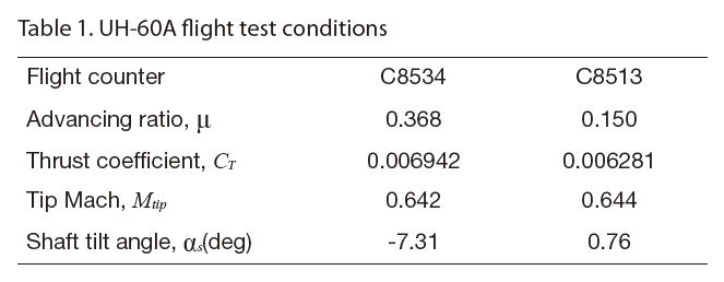
UH-60A flight tests were conducted in 1993-1994 for the NASA/Army UH-60A Airloads Program (Kufeld et al.,1994). The flight conditions cover level flights and transient maneuvers, and the measured data included aerodynamic pressures, structural loads, control positions, and rotor forces and moments. This extensive database (Bousman et al., 2005) was widely used for validating helicopter aerodynamic analysis tools (Ananthan et al., 2008; Bousman,2009; Bousman and National Aeronautics and Space Administration Moffett Field CA Ames Research Center,2003; Datta et al., 2006; Howlett, 1981; Potsdam et al., 2004;Yeo et al., 2002). In the present study, two level flight cases,C8534 and C8513, were selected. The flight conditions are summarized in Table 1. The fight counter C8534 is a high speed forward flight case with an advancing ratio of 0.368 in which transonic effects at the advancing side dominate the blade airloads. On the other hand, significant BVI occurs for the fight counter C8513, which is a low speed forward flight case with an advancing ratio of 0.15.
[Table 1.] UH-60A flight test conditions

UH-60A flight test conditions
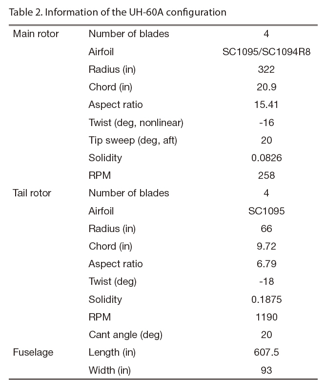
[Table 2.] Information of the UH-60A configuration

Information of the UH-60A configuration
[Table 3.] Pitch and flapping angles
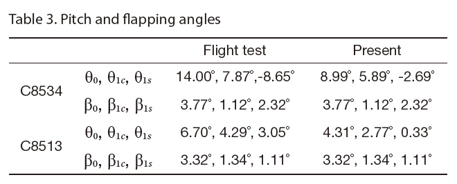
Pitch and flapping angles
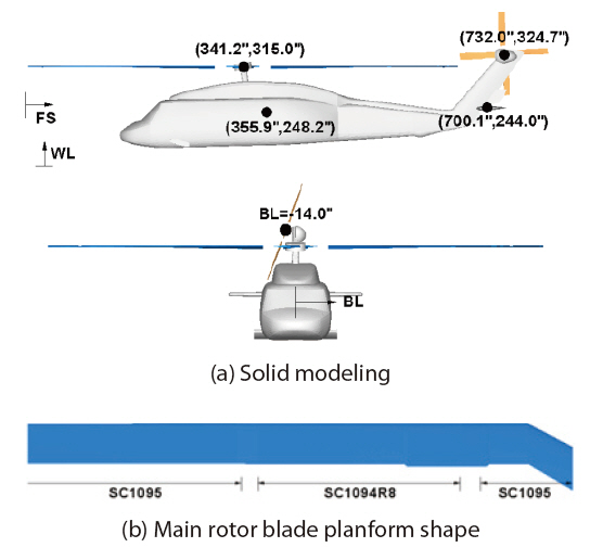
In Fig. 1, the solid modeling of the UH-60A configuration and the main rotor blade planform shape are presented.The UH-60A helicopter has a fully articulated main rotor that consists of four blades and rotates counter-clockwise.Each blade is made of SC-1095 and SC-1094 airfoil sections with a nonlinear twist of 16 degrees, and has an aspect ratio of 15.41 (Fig. 1b). The tail rotor is made of four blades that have an aspect ratio of 3.1, and rotates top-aft with a cant angle of 20 degrees. The gear ratio of the tail rotor to the main rotor is 4.62, and consequently, the blade tip speeds of the two rotors are almost the same considering the radius of the blades of the two rotors. Typical lengths of the fuselage are 607.5 and 93 inches in longitudinal and lateral directions,respectively. Each component was integrated to relative positions with respect to the station coordinates, fuselage station (FS), water line (WL), and butt line (BL) as shown in Fig. 1a. Further information about the UH-60A configuration is summarized in Table 2, and more details can be found in Bousman et al. (2005).
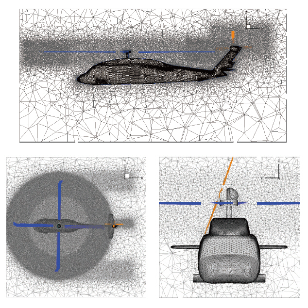
In Fig. 2, the mesh distributions around the UH-60A configuration and on the solid surface are presented.Fine cells are concentrated at the outboard portion of the main rotor disk plane to capture the rotor wake and the aerodynamic interaction phenomena more accurately.For the C8534 case, the computational mesh contained approximately 1.79M nodes and 9.69M tetrahedral cells. The mesh was more refined for the C8513 case, in which 2.67M nodes and 14.68M tetrahedrons were used to better resolve the aerodynamic interaction between the rotor wake and the components in this low-speed flight condition.
A main rotor trim procedure was applied to both fight cases in order to retain the predicted rotor thrust to each desired level (Table 1) and to eliminate the rotor pitching and rolling moments. The trim controls consist of collective(θ0), lateral cyclic (θ1c) and longitudinal cyclic (θ1s) pitch angles, and the trim state was obtained by adjusting the trim controls iteratively using a Newton-Rapthon method(Yang et al., 2000). During the trim calculation, the flapping angles (β0, β1c, and β1s) were set to the values used in the flight test because the structural properties of the UH-60A configuration were not available, which was needed for a free-flight trim analysis involving blade flapping responses.The comparison of pitch and flapping angles between the prediction and flight test data are presented in Table 3.
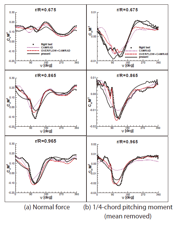
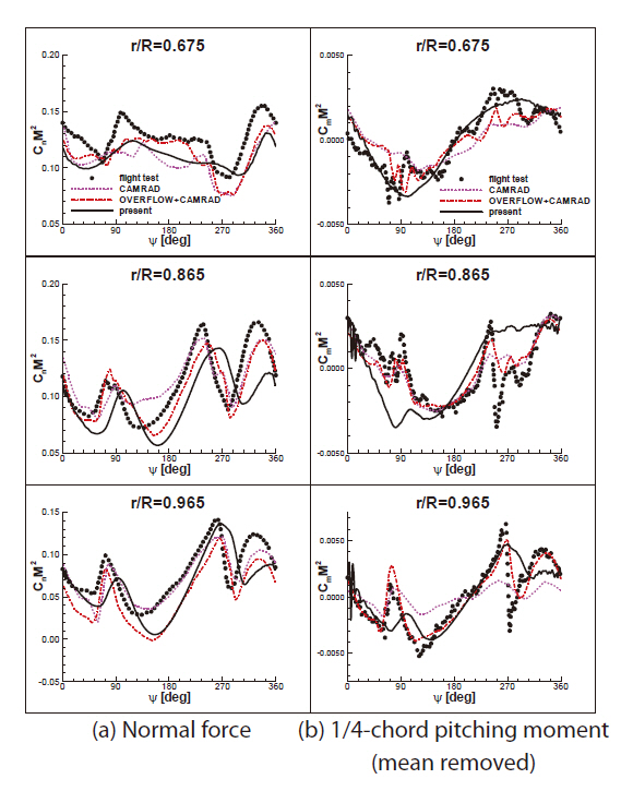
In Fig. 3, the predicted unsteady airloads on the blade of the main rotor, sectional normal force (CnM2) and 1/4-chord pitching moment (CmM2, mean removed), are presented at three selected spanwise stations for the C8534 case. The results were compared to the flight test data(Bousman et al., 2005) and other calculations (Potsdam et al., 2004) by the CAMRAD-II (Johnson, 1998) and the coupled OVERFLOW+CAMRAD-II method. In the figure, the CAMRAD-II results show an azimuthal phase lag of negative normal force and under-predicted pitching moment at the outboard parts of the blade near the azimuth angle of 90 degrees, indicating poor prediction of the transonic effect.In contrast, the OVERFLOW+CAMRAD-II calculation results were more accurate. The present calculation provided comparable prediction accuracy of the airloads. However,a high-frequency pitching moment at the 86.5% spanwise location in the advancing side was not well captured. This was because the present calculation neglected the viscosity of the flow as well as the aeroelastic deformations, particularly in torsion.
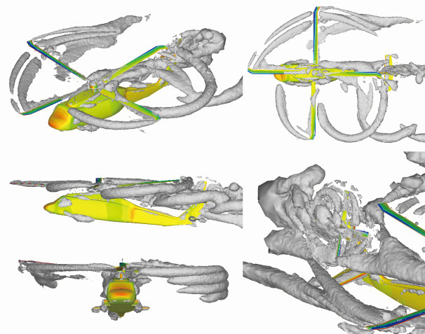
Figure 4 shows the wake structures represented by the iso-surface of λ2-criterion for C8534 case when the reference blade of the main rotor was located at the azimuth angle of zero degrees. The advancing blade strongly interacted with the roll-up vortices trailed from the blade tip and near the sweep break, causing a high-frequency pitching moment. In contrast, when the blade retreated from the freestream, the BVI was not observed because the wake quickly transported downstream and in the downward direction due to the high flight speed and the nose-down shaft tilt angle.
In Fig. 5, a comparison of the unsteady airloads, normal force and 1/4-chord pitching moment (mean removed), was made for the C8513 case. Significant down-up and up-down pulse loadings were observed near the azimuth angles of 90 and 270 degrees, respectively, and this pattern was quite different from those of the high-speed flight case (C8534). Although the present results show small deviation in the phase of the unsteady loading from the flight test data, the overall results agreed well with the test flight data (Bousman et al., 2005) and other calculations (Potsdam et al., 2004).
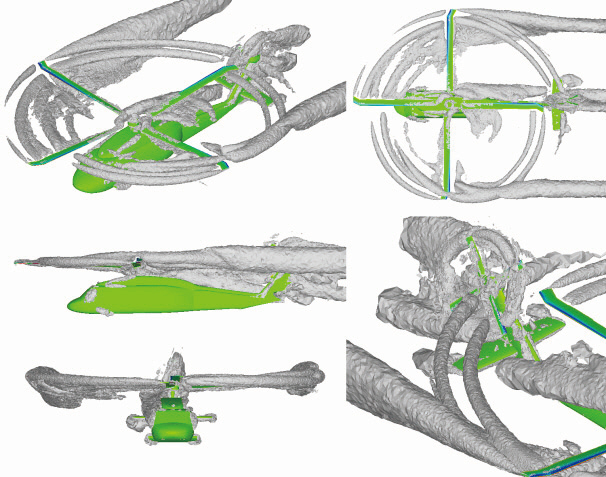
In Fig. 6, the wake structure for the C8513 case is presented when the reference blade of the main rotor is located at the azimuth angle of zero degree. The rotor wake remained much closer to the rotor disk plane and stayed longer, compared to the high-speed flight case (C8534). Furthermore, the diskvortices at the lateral edges of the rotor disk plane, which resulted from intertwining individual tip vortices, were more evident. The disk-vortices strongly interacted with the blade near the azimuth angles of 90 and 270 degrees, and as a result, the down-up and up-down pulse loadings were induced as shown in Fig. 5.
In order to investigate the aerodynamic interference between the wake and the helicopter components in detail,additional calculations were conducted for both isolatedrotor(MR) and rotor-fuselage (MR+FS) configurations for identical flight conditions as the low-speed flight case(C8513), and the results were compared to each other.
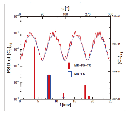
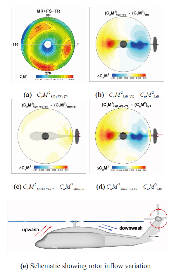
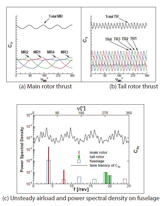
In Fig. 7, the effects of the main rotor and the tail rotor on the fuselage loading are presented. The MR+FS+TR and MR+FS configurations were compared to the results in order to distinguish the main rotor and tail rotor effects. In the figure, the time-varying thrust component of the fuselage loading for one revolution of the main rotor and the power spectral density (PSD) of the loading are presented both in time and frequency domains. The vibratory fuselage loading for the rotor-fuselage configuration was predominately at 4/rev, indicating the blade passage effect of the four-bladed main rotor. After including the tail rotor in the configuration,additional higher harmonics, 18/rev~19/rev, were added to the fuselage loading. The gear ratio of the tail rotor to the main rotor was about 4.6, and therefore these higher harmonics were caused by the tail rotor blade passage effect.
Figure 8 shows the effect of the fuselage and the tail rotor on the main rotor blade normal force. In Fig. 8a, the blade sectional normal force of the MR+FS+TR configuration is presented for one revolution of the main rotor, and in Figs. 8b-d, the differences of the normal force between the MR+FS+TR, MR+FS and MR configurations are presented.The flow is deflected upward in front of the rotor hub and in the downward direction behind the hub, as shown in Fig.8e, due to the blockage of the fuselage. These upward and downward flows around the fuselage effectively changed the local angle of attack of the main rotor blade. As a result,the normal force near the azimuth angle of 180 degrees increased though it decreased near an azimuth angle of zero degree (Fig. 8b). Furthermore, the tail rotor increases normal force at the outboard portion of the blade when it is located at the azimuth angle of zero degree (Fig. 8c).
3.2 Generic Helicopter Configuration
The second application of the present flow solver was made to a generic complete helicopter configuration at various flight conditions. The helicopter consisted of a fourbladed main rotor rotating clockwise, fuselage, and a tail rotor of four blades with top-aft rotation. The gear ratio of the tail rotor to the main rotor is about 4.86. The solid modeling of the configuration is presented in Fig. 9.
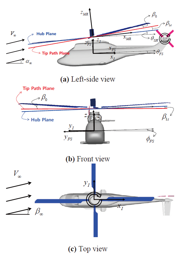
Definitions of blade flapping motion (conning β0, longitudinal β1c, and lateral β1s), fuselage attitude (roll φ
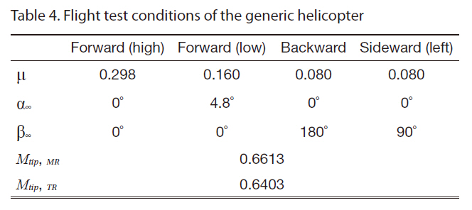
[Table 4.] Flight test conditions of the generic helicopter

Flight test conditions of the generic helicopter
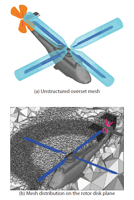
Figure 10 shows the unstructured overset computational mesh of the generic helicopter configuration. Again, fine cells were distributed on the rotor disk plane, particularly near the blade tip to better resolve the rotor wake. The total number of grid points and tetrahedral cells is about 2.93M and 16.1M, respectively.
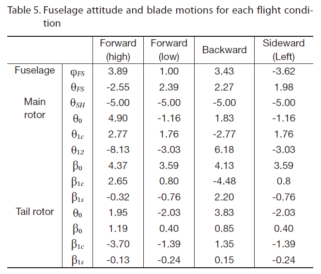
[Table 5.] Fuselage attitude and blade motions for each flight condition

Fuselage attitude and blade motions for each flight condition
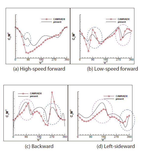
In Fig. 11, a comparison of the unsteady normal force between the four flight conditions is presented. The results were also compared to the CAMRAD-II calculated results for validation. The down-up and up-down pulse loadings show a dominant unsteady wave form of the normal force, which appears quite differently depending on the flight condition.In the case of high-speed forward flight, a down-up pulse loading occurred near an azimuth angle of 90 degrees,but the pulse strength is relatively small. In the low-speed forward flight, down-up and up-down pulse loadings appear near the azimuth angles of 90 and 270 degrees, respectively.In the backward flight, the pulse loadings appear opposite to those of the low-speed forward flight because the advancing and retreating sides are switched. In the left-sideward flight,the pulses were shown near azimuth angles of 180 and 360 degrees, respectively. The overall results show a similar tendency to those of the CAMRAD-II results.
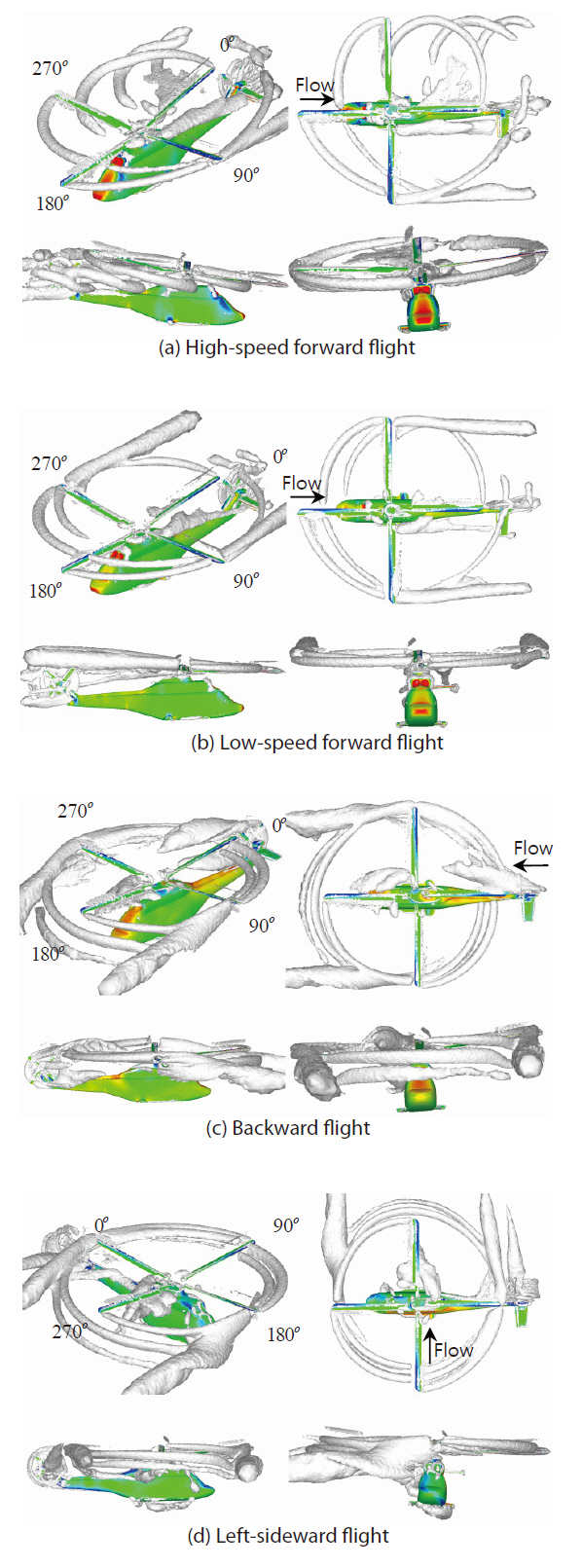
In Fig. 12, a comparison of the wake structures between the four flight conditions is presented by the λ2-criterion for visualization. For high-speed forward flight, the rotor wake was quickly convected downstream, and single disk-vortex develops at the azimuth angle of 90 degrees, causing the down-up pulse loading shown in Fig 11a. For other flight cases with relatively lower speeds, the wake stayed longer in the rotor disk plane, and a pair of disk-vortices develop at the outer edges of the disk plane and at two different azimuthal stations, 90 and 270 azimuth angles for the low-speed forward and backward flights, and the azimuth angles of zero and 180 degrees for the left-sideward flight. Consequently, when the blade encountered the disk-vortices, a pulse loading was created as shown in Figs. 11b-d. For the backward flight case, the tail rotor wake was convected into the main rotor disk (Fig. 12c), and affected the main rotor blade loading, showing an abrupt drop in the normal force at the azimuth angle of zero degree (Fig. 11c). This effect was well captured by the present CFD calculation.
Figure 13 shows the effect of aerodynamic interaction between the main rotor, fuselage, and tail rotor at the highspeed flight condition. In the figure, unsteady airloads on the main rotor, fuselage, and tail rotor for one revolution of the main rotor and the PSD of each airload were also presented.The predominant frequencies of the fuselage normal force were 4/rev and 19.4/rev, and these frequencies were almost identical to those of the main rotor and tail rotor thrusts,respectively. This indicates that the lower frequency loading was exclusively associated with the blade passage effect of the main rotor, while the higher frequency was primarily associated with the passage effect of the tail rotor, which produced pressure pulses on the empennage part of the fuselage, particularly on the horizontal tail.
In the present study, unsteady flow simulations of complete configurations of the UH-60A and the generic helicopters were conducted, and the flow fields around the configurations and the aerodynamic interference between the main rotor, fuselage, and tail rotor were investigated. An unstructured mesh flow solver was used for the simulations,coupled with an overset mesh technique to describe the relative motion among the three components.
For the UH-60A configuration, the predicted results compared well to the flight test data and other calculated results within the accuracy of rigid blade simulations. The fuselage affected the main rotor airloads by changing the rotor inflow distribution.
For the generic helicopter configuration, high-speed and low-speed forward flights, a backward flight, and a sideward flight were simulated. The predicted results agreed well with those of the CAMRAD-II comprehensive analysis code. The main rotor blades strongly interacted with a pair of diskvortices at the outer edges of the main rotor disk plane,which led to high pulse airloads on the blade. These loadings appeared differently depending on the flight condition. The conclusion followed that the blade passage effect of the main and tail rotors dominated the vibratory airloads on the fuselage.