As the application of composite materials to aircraft structures has increased in various fields (Niu, 2005; Park et al. 2009), ballistic-tolerant design concepts have become a topic of interest for designers. Particularly in the design of fighters, it is necessary to consider the ballistic resistance of structures that are exposed to the potential danger of ballistic impact. In helicopters, survivability after a ballistic impact is required for the rotor blades, control, and the hub.The application of composite materials to armor already has a long history due to not only the ballistic resistance but also the excellent specific stiffness and strength offered by these materials.
The behavior of composite structures during a highvelocity impact is affected by a variety of factors, including the impact velocity, shape, mass and stiffness of the impactor, and laminate properties. The complicated failure mechanism of a composite laminate is an especially important obstacle in numerical simulations. Accordingly,numerical approaches regarding a high-velocity impact are considered to be a challenging issue. For this reason, mainly tests have been used in this area (Jung et al., 2006; Lee et al.,2001; Liu, 2004).
There are two approaches regarding numerical methods,i.e., microscopic and macroscopic. In the microscopic model, the constituents of composite materials such as the reinforcing fiber and matrix are treated as separate materials(Ji and Kim, 2006). In another microscopic method,composite materials are idealized as a combination of unit cells consisting of the fiber and the matrix (Tabiei and Ivanov, 2002; Unosson and Buzaud, 2000). The macroscopic model assumes a composite laminate to be a structure made of a homogenous and anisotropic material. It is useful and efficient for simulating the structural behavior, as the constituents of the composite materials are not separately handled. However, it is somewhat limited in simulations of failure due to the combined effect of the fiber and the matrix(Ji and Kim, 2006).
While a number of papers (Kong et al., 2007; Lee et al.,2008; Park et al., 2008) are available related to low-velocity impacts on composite structures, a limited number of studies related to high-velocity impacts are available to the public.Even in the available literature, only limited information is provided, and data such as the stacking sequence and material properties are frequently excluded.
Tabiei et al. (2001, 2002) performed an analysis of a highvelocity impact on flexible Kevlar fabric using a homogenized microscopic unit cell approach. They then compared their results with test results. LS-DYNA provides the user defined material (UMAT) function to simulate a failure through impact on composite structures. Using this method, Hoof(1999) and Yen (2002) conducted numerical analyses of laminated composite structures.
The present paper has used a numerical analytic method for a Kevla29/Phenolic fabric laminate under the highvelocity impact of an fragment simulation projectile (FSP). A nonlinear explicit finite element program, LS-DYNA version 971 (Livermore Software Technology Corporation, 2007),was applied using the element eroding contact algorithm.In the algorithm, where the stress level exceeds a certain criterion, the associated element is eroded from the finite element model. Delamination is an important failure mode in impact problems. The tiebreak contact interface was used to simulate delamination between composite layers. The finite element results were compared with the test results in an earlier study (Hoof, 1999).
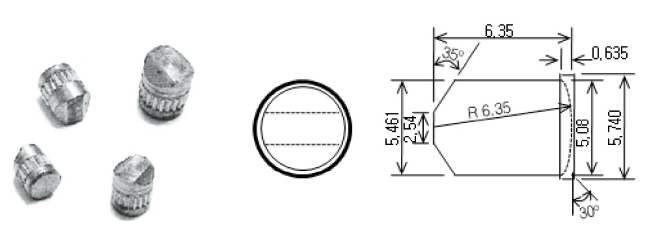
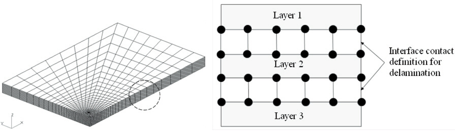
Finite element analysis was conducted for the Kevlar29/Phenolic fabric laminated composite plate shown in Fig. 1.The plate has dimensions of 152.4 (length) × 101.6 (width)× 9.5 (thickness) (unit: mm). The long edges are free, and the short edges are simply supported. The impact velocities considered are 483, 545, and 586 m/s. The impactor FSP shown in Fig. 2 has a diameter of 5.59 mm and weight of 1.1 g. The FSP impacts upon the center of the plate. For finite element modeling, a symmetry condition is used. The material properties of the composite and the impactor are given in Table. 1 and 2, respectively (Hoof, 1999).
Key issues for finite element analysis of a composite laminate under a high-velocity impact include definitions of the material properties, development of a proper contact algorithm, and failure criteria. It is very difficult to define material properties that are valid for a wide range of impact velocities. Accordingly, it is important to find an adjustment factor for material properties to correlate the results of finite element analysis with test results. In the early design phase,many parameters for operating LS-DYNA were adjusted through iterative comparisons between the test and analytic results. To adjust the parameters, we use a trial and error method. First, we set the parameters as they are by default in the program and undertake analysis. We then change these parameters slightly when there is a mismatch between the results of numerical analysis and the test. After several iterations, suitable parameters can be found.
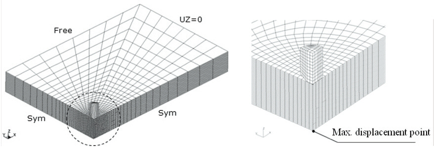
The finite element model is shown in Fig. 3, where a quarter of the plate is idealized using the symmetry condition. An
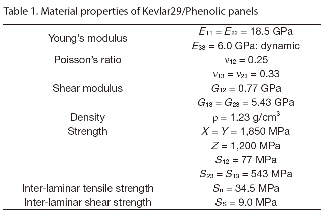
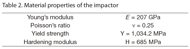
[Table 1] Material properties of Kevlar29/Phenolic panels

Material properties of Kevlar29/Phenolic panels
[Table 2] Material properties of the impactor

Material properties of the impactor
eight-node hexagonal solid element was used to simulate the plate and the impactor. Each layer of the plate was modeled using two solid elements through the thickness, and the minimal element size was 0.25 mm × 0.83 mm at the center of the plate, which was the point of impact. The failure criterion for the composite material is a stress-based equation from Schweizerhof et al. (1998).
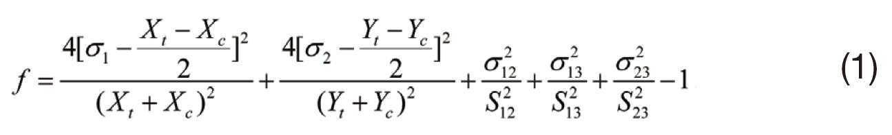
In Eq. (1),
σ1, σ2 : Stresses in the fiber and transverse directions,respectively.
σ12, σ13, σ23: Shear stresses.
Y
S12, S12, S23 : Shear strengths.
When the index,
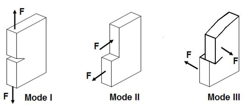
laminar normaland shear stresses exceeds a critical value,the tiebreak contact interface is deleted and delamination occurs (Hoof, 1999; Ji and Kim, 2006; Livermore Software Technology Corporation, 2007). The failure of the tiebreak contact interface is determined by a combination of the fracture modes, I, II, and III, as shown in Fig. 5. The failure criterion for the tiebreak is given in Eq. (2)
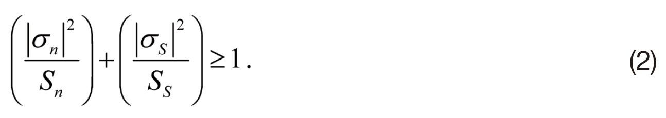
In Eq. (2)
The steel impactor was modeled with an elastic-plastic material. The von-Mises yield criterion for the impactor is defined as follows (Livermore Software Technology Corporation, 2007):
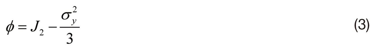
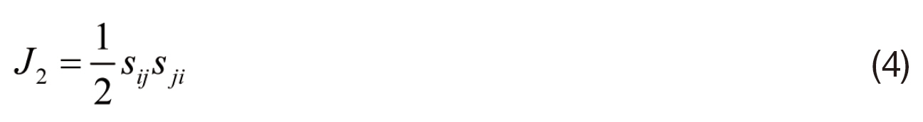
with the following notation.
The yield stress, σ
plastic strain, εp

In Eq. (5),
σ0: Specified threshold stress.
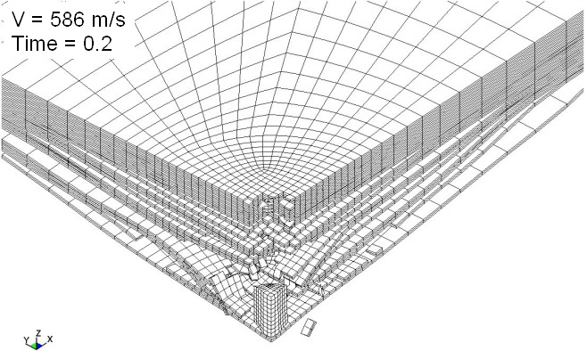
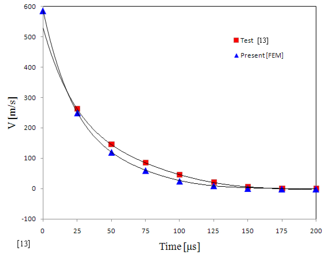
The failure, perforation, backplane deflection, and velocity of the impactor are the important parameters in the analytic results for a high-velocity impact on a composite plate.The behavior of the composite panel 200 μs after the initial contact from a 586 m/s-velocity impactor is shown in Fig.6. As shown in the figure, the panel was nearly completely perforated by the impactor. Extensive delamination occurred between the bottom plies of the panel, whereas this was not observed in the upper plies. Figure 7 shows the velocity-time history of the impactor. The present results of finite-element
analysis are in good agreement with the aforementioned test results (Hoof, 1999).
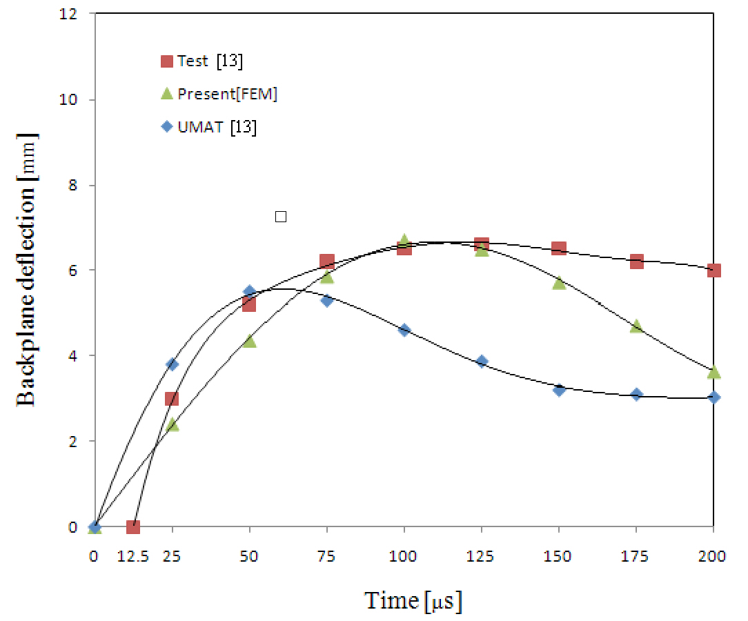
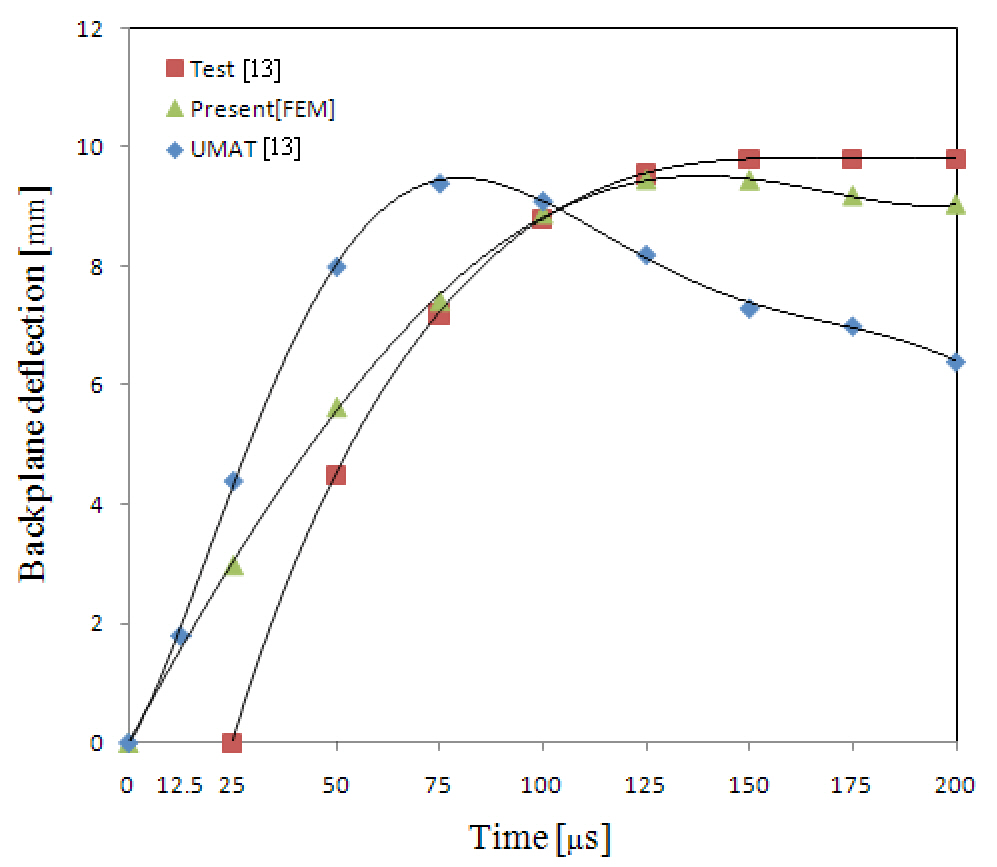
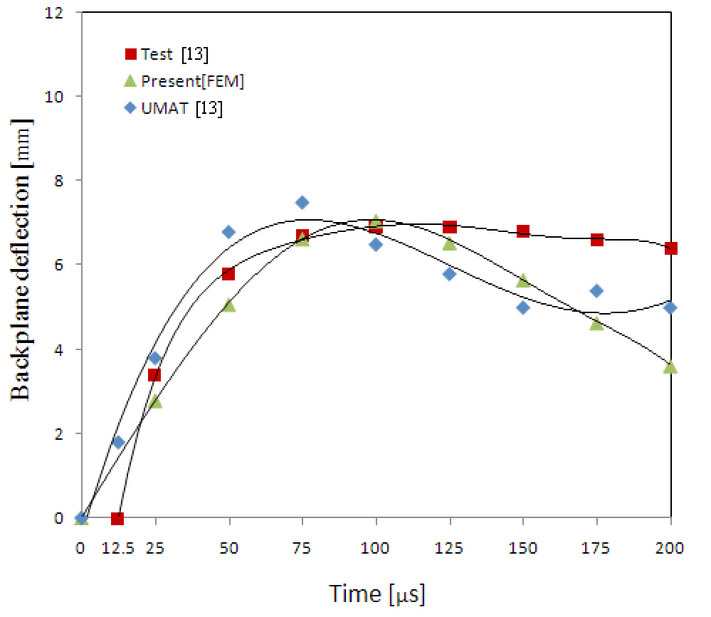
The results regarding the backplane deflection of a composite plate under various impact velocities are shown in Figs. 8-10 in comparison with the test and numerical results based on the UMAT model (Hoof, 1999). As discussed in a relevant study, namely (Hoof, 1999), the initial time of commencement of deflection was not precisely measured during the test. Except for the very early stage of the impact event, the deflection was believed to have been measured correctly. Accordingly, the authors of the aforementioned study, namely (Hoof, 1999), did not shift the test curve to position the starting point at the origin. This is also true for the present paper. The finite element results here show excellent agreement with the test results, including the maximum deflection, apart from the early stage of the event.The springback phenomenon is natural after the maximum deflection under the impact occurs. While the test results do
not account for this phenomenon, it is easily observable in the finite element analyses.
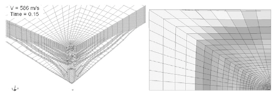
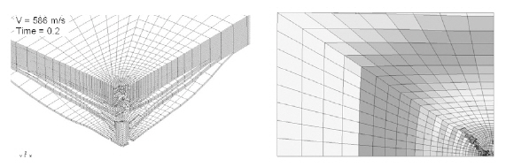
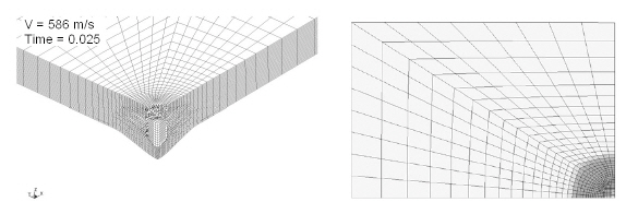
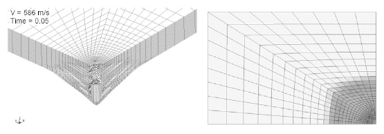
Figures 11-14show the progress of damage in the composite plate at an impact velocity of 586 m/s. The entire process from the initial impact to the final penetration of the impactor through the plate was successfully simulated. Figure 11 shows the damage at 25 μs after the initial strike by the impactor. Regardless of the short time for the response,the impactor penetrated into more than half the plate and the backplane deflection reached nearly 3 mm. However,the damage zone was limited to the region close to the impact point. The finite elements where the impactor passed through failed and were therefore eroded. Figure 12 shows the results at 50 μs after the initial impact. The maximum backplane deflection was approximately 6 mm, which was double the value at t = 25 μs. Extensive delamination around the impactor and through the thickness are observed in the figure. Figures 13 and 14 show the damage of a composite plate at t = 150 and 200 μs, respectively. Delamination in the layers close to the backplane occurred over nearly the entire plate, and the impactor began to leave the plate after penetration.
A finite element model using LS-DYNA was developed to simulate the high-velocity impact response of a Kevlar29/Phenolic composite plate. The interface between the laminas was modeled by a tiebreak contact algorithm, while the interaction between the impactor and the laminate was simulated using a surface-to-surface eroding contact algorithm. Numerical analyses were conducted at impact velocities of 483, 545, and 586 m/s of a steel impactor. The
results of finite element analysis were in good agreement with the test results and in especially excellent agreement regarding the maximum backplane deflection. The present finite element model also successfully simulated the progress in damage from the initial impact to the final penetration of the composite plate.