A finite element analysis for the wing and landing gear of a composite target-drone air vehicle was performed. For the wing analysis, two load cases were considered: a 5g symmetric pull-up and a -1.5g symmetric push-over. For the landing gear analysis, a sinking velocity of 1.4 m/s at a 2g level landing condition was taken into account. MSC/NASTRAN and LS-DYNA were utilized for the static and dynamic analyses, respectively. Finite element results were verified by the static test of a prototype wing under a 6g symmetric pull-up condition. The test showed a 17% larger wing tip deflection than the finite element analysis. This difference is believed to come from the material and geometrical imperfections incurred during the manufacturing process.
Composite materials reduce the structural weight of an aircraft, and thereby improving its efficiency. Composite materials were extensively utilized in the Boeing 777, A-350, and F-22. Composite materials are generally light in weight and very strong; however, the uses of composite materials are not limited to only advance large scale commercial planes or fighter jets. Composite materials are also powerful alternatives to metal in small scale unmanned aerial vehicles (UAVs). Small scale UAVs have experienced considerable development in both civil and military applications. Accordingly, the demand for the systematic research of composite materials has also increased.
The regulations for UAV structural design are not well established in comparison to manned vehicles; thus, UAV design often depends on the manufacturers’ experiences. In addition, a limited number of papers on UAV structural design have been published. Romeo et al. (1995, 1998, 1999, 2003), Cestino (2006), and Frulla and Cestino (2008) used composite materials to develop a high altitude long endurance (HALE) UAV and a solar powered airplane. Gadomski et al. (2006) used composite materials to make a composite UAV and proposed an optimization method for the wing structure. Young (1986) introduced composite materials to the landing gear of a UAV and compared the resultant performance with previous metal landing gear.
In the present paper, the structural design and analysis results of a relatively heavy target-drone made of composite materials are presented. The main objective was to develop a composite target-drone and verify its structural performance by tests and a finite element analysis. The static strength and buckling of the wing structures were examined. A dynamic analysis was conducted for the landing gear. A static strength test for the wing was performed by sand bag loading.
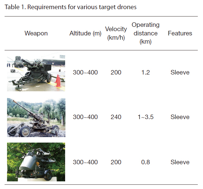
[Table 1.] Requirements for various target drones

Requirements for various target drones
2. Specification and Load Conditions
2.1 Specification of target-drone
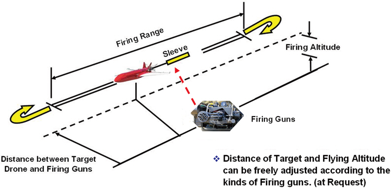
Target-drones can be broadly classified into two types: direct and indirect shooting target-drones. For an indirect shooting target-drone, an air vehicle pulls a sleeve that functions as a shooting target, as shown in Fig. 1. In the design of a target-drone, not only should the performance requirements be satisfied, but reduction manufacturing cost is also critical.
The design of a target-drone aircraft is usually dependent on the type of flak used. Table 1 lists the target-drone requirements depending on three kinds of flak: M-167 Vulcan, Oerlikon flak and M55/M45D flak. The present air vehicle was designed according to the Oerlikon flak conditions.
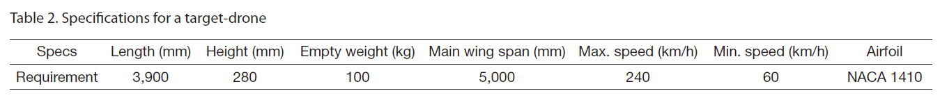
[Table 2.] Specifications for a target-drone

Specifications for a target-drone
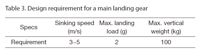
Oerlikon flak entails the highest velocity requirements. Table 2 shows the specifications of the vehicle. Table 3 shows the requirements for the main landing gear of the plane.
The Federal Aviation Administration (FAA) provides regulations for commercial aircrafts; MIL-spec is limited to military aircrafts. The regulations for a small scale unmanned aircraft are not clearly defined in the Federal Aviation Regulations (FAR). In this study, the load conditions were determined based on the experience from the operation of similar UAVs. FAR, Part 23 (FAA), which is the basic regulation for commercial aircrafts, was also referenced.
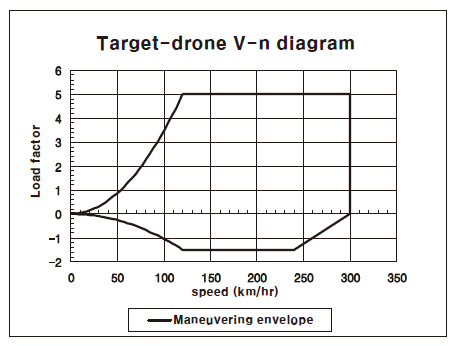
For the wing design, the following two loading cases must be sustainable: a 5g symmetric pull-up and a -1.5g symmetric push-over conditions. For the landing gear, a 2g landing case was considered. The V-n diagram shown in Fig. 2 presents these conditions.
For the wing and fuselage, glass fabric was mainly used because it is cheaper than carbon composite and is relatively stiff and strong. A carbon composite was used for the main landing gear, however, in order to sustain the landing loads. The composite materials selected for the wing and fuselage were H612 and WR580A glass fabric from Hankuk Fiber Co., Ltd. (Milyang, Korea), with room temperature curing resin and hardener. Carbon fabric WSN3K from SK Chemical (Seongnam, Korea) was selected for the landing gear. Aluminum pipe and two kinds of wood, balsa and plywood
[Table 3.] Design requirement for a main landing gear

Design requirement for a main landing gear
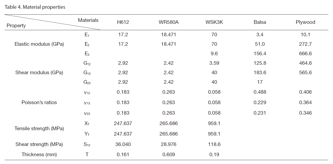
[Table 4.] Material properties

Material properties
were partially used in the target-drone.
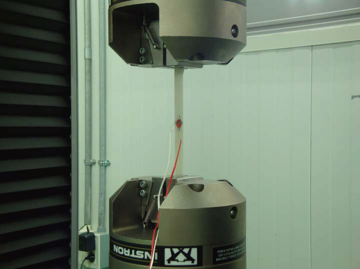
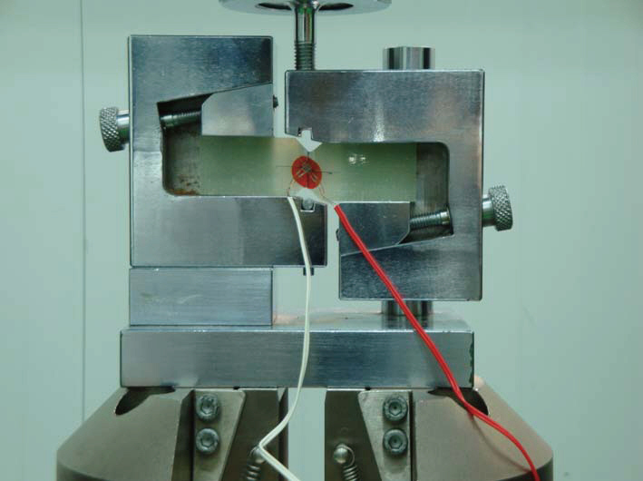
Basic material properties for the glass and carbon fabric were obtained through tests conducted according to ASTM-D3039 (tensile test) and ASTM-D5379 (V-notch shear test) standards (ASTM International, 2003). Figures 3 and 4 show the test set-up. Table 4 shows the measured material properties.
Mechanical properties of the H612 and WR580A glass fabric were obtained through testing and those of balsa and plywood were gathered from (US Forest Products Laboratory, 1962, 1964).
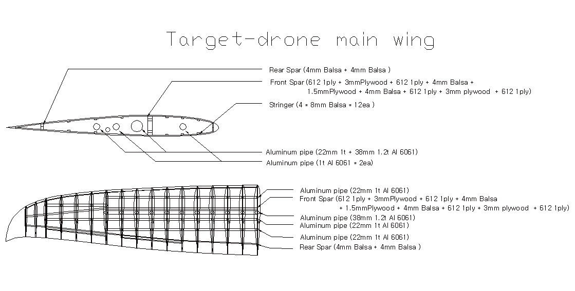
The wing of the target drone shown in Fig. 5 had a 5-m wing span and 0.7-m root chord. The structures of the target-
drone’s main wing were designed to sustain a 5g symmetric pull-up and a -1.5g symmetric push-over conditions.
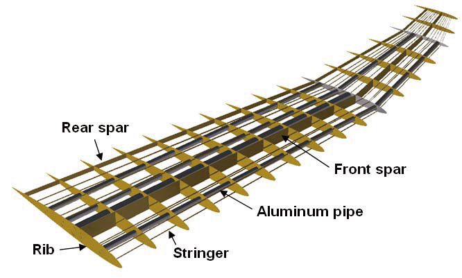
Generally, the understructure of a wing consisted of spars, ribs and stringers. The spars of large planes commonly have an I-cross section shape with flange and a web. However, the present target-drone’s spars were not divided into a flange and web so as to reduce the structural complexity and manufacturing cost. This configuration is frequently applied to small aircrafts such as unmanned air vehicles. Several reinforcing aluminum pipes were installed in the span-wise direction.
The front spar had a thickness of 6-mm. It was made with a sandwich structure comprising a combination of balsa, plywood and glass fabric. The ribs were made in a similar fashion. Stringers were added to reinforce the wing skin. The final design of the wing had 2 spars, 17 ribs and 4 aluminum pipes. A ply of glass fabric was adhesively bonded over the outer skin to create a smooth surface. The structural layout of the wing is shown in Fig. 6.
When an aircraft lands at a normal sink rate, a large amount of energy has to be absorbed by the main landing gear, which undergoes large deformations and rotations. The desired characteristics of the main landing gear are high strength, lightweight, medium stiffness and high elastic strain energy storage capacity.
The landing gear was designed based on the required ability to sustain a 2g applied load or landing with a minimum vertical velocity of 1.4 m/s. The main landing gear was laidup using 40 plies of WSN3K with a stacking sequence of [45/0/-45/90]5s.
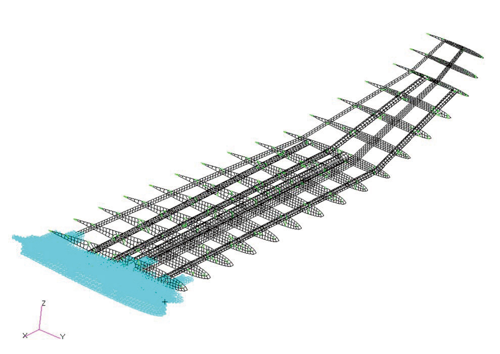
The target-drone wing consisted of skin, a front spar, a rear spar, ribs, and stringers. The first step in the finite element analysis was to construct the geometry. The geometry of the wing was generated by computer aided three-dimensional interactive application (CATIA) and imported to Altair/Hypermesh. Next, a mesh was created for the finite element model using the geometry. Shell elements (CQUAD4 provided in MSC/Nastran) were used in the modeling of the skin and the front and rear spars while the stringers were modeled using a one-dimensional rod element (CROD). The finite element model of the wing is presented in Fig. 7.
A linear static analysis using MSC/NASTRAN was conducted. The Tsai-Wu failure criterion was adopted to evaluate the failure of the composite parts while the von-Mises stress was used for the aluminum parts. Analyses were performed for 2 cases of loading: a 5g symmetric pull-up and a -1.5g symmetric push-over. Buckling was also examined
[Table 5.] Main wing analysis results
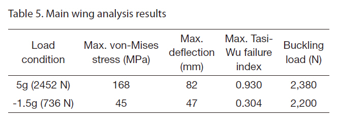
Main wing analysis results
for the entire wing structure.
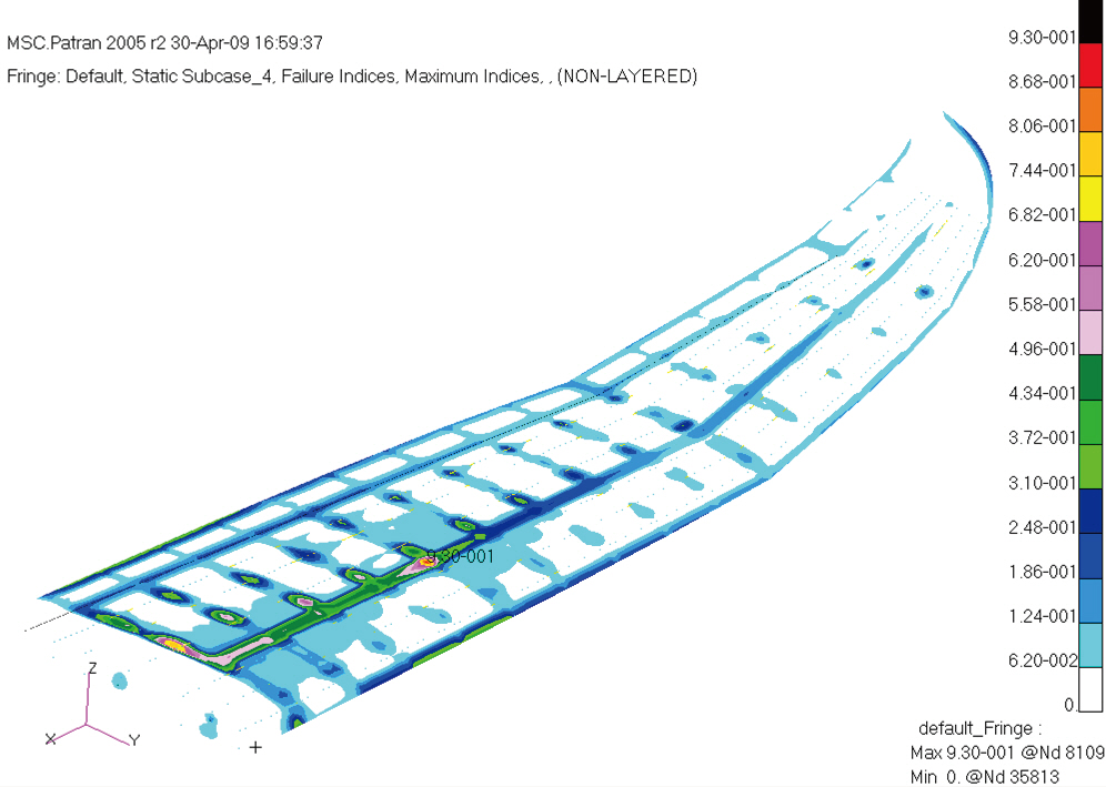
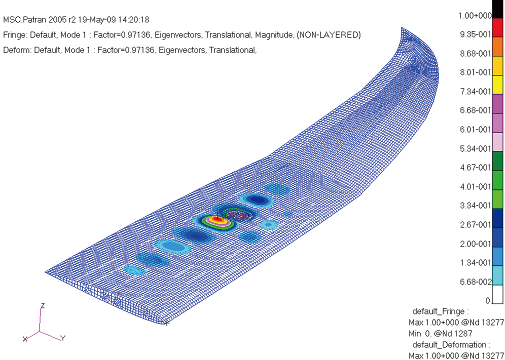
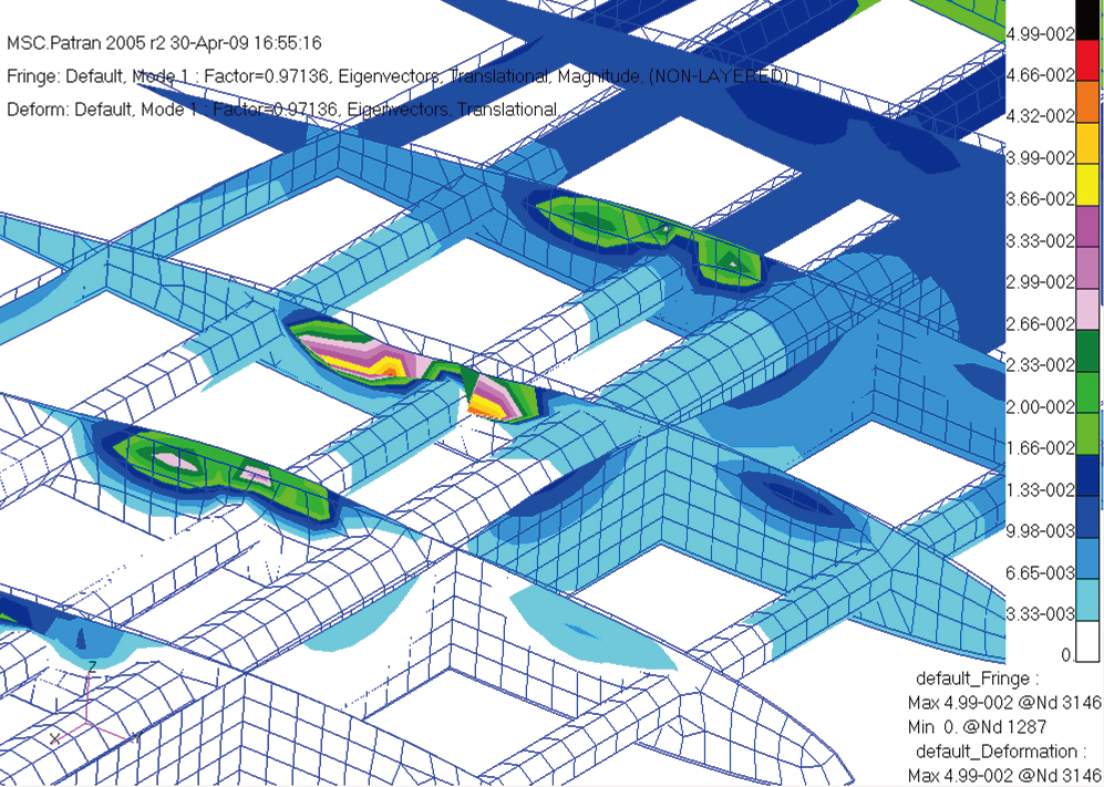
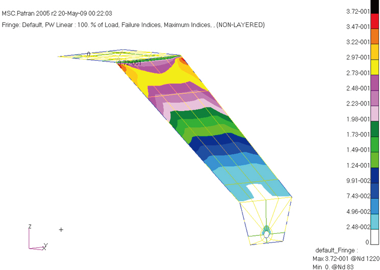
Table 5 lists the analysis results of the wing for two load conditions. In the case of a -1.5g symmetric push-over, the maximum failure index using the Tsai-Wu criterion was smaller than 1, indicating that the structure was still robust. In the case of 5g loading condition, the maximum Tsai-Wu index was found to be 0.930, but the buckling load was lower than the maximum internal load in the 5g loading condition, indicating the possible existence of local buckling. The maximum Tsai-Wu failure index in the skin is shown in Fig. 8 and the buckling analysis results are shown in Figs. 9 and 10. As shown in the figures, the wing skin and ribs can undergo local bucklings. This indicates that the structure required a modification for the stability requirement in the 5g loading condition. To prevent skin buckling, reinforcements were required in wing structure, such as additional more stringers or ribs.
5.2 Main landing gear analysis
The main landing gear had two requirements, one for a static load condition and the other for a dynamic load condition. To characterize the behavior of the landing gear in the static load condition, a non-linear static analysis using MSC/NASTRAN was conducted. LS-DYNA meanwhile was used for a dynamic analysis of the landing gear.
5.2.1 Static analysis
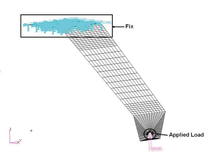
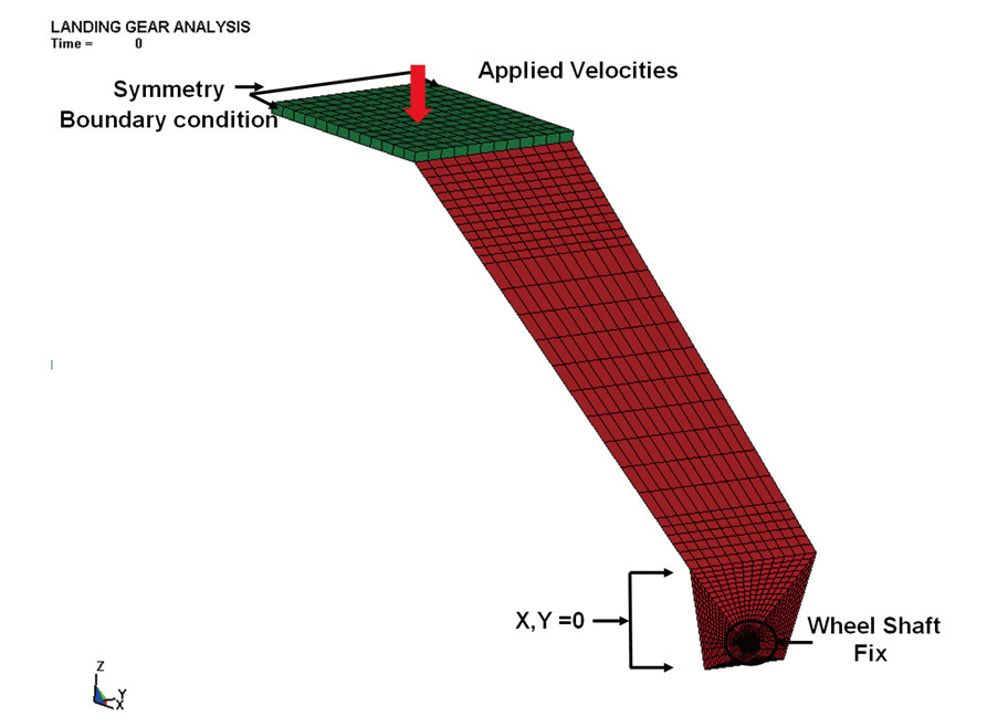
MSC/NASTRAN, the most reliable finite element program for air vehicles, was used for the static analysis of the landing gear. The landing gear was made of a carbon fabric prepreg WSN3K. A total of 40 plies were laminated to yield a final thickness of 7.6 mm. A finite element model was created using shell elements (CQUAD 4). Taking advantage of the symmetry of the landing gear, only half of the structure was modeled. The material properties of the fabric prepreg are given in the Table 6. The maximum stress criterion and the Tsai-Wu failure criterion were chosen to predict the failure. A distributed load corresponding to a load factor of 2 was applied at the contact area between the landing gear and the wheel shaft. The finite element model with all the constraints and applied load is shown in Fig. 11. Considering
[Table 6.] Main landing gear static analysis results of 2g (981 N) load condition
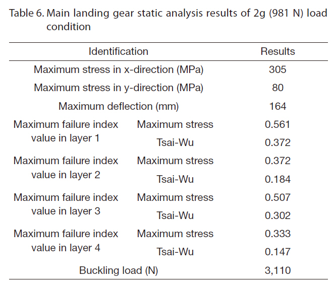
Main landing gear static analysis results of 2g (981 N) load condition
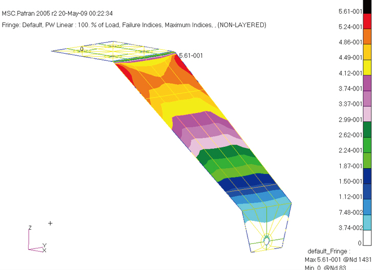
that the landing gear can experience a large displacement, a nonlinear static analysis was performed. The failure indices by the maximum stress criteria and the Tsai-Wu failure criterion are shown in Figs. 12 and 13, respectively. The results showed that the current design had enough margins of safety, which was made of 40 plies of carbon prepregs in the stacking sequence of [45/0/-45/90]5s. Maximum stress was predicted at the curved region where supports were attached to the landing gear. Failure indices were lower than 1.0 by both failure criterion.
5.2.2 Dynamics analysis
The contact between the composite strut and the wheel shaft of the landing gear can result in a high stress concentration, especially in during harsh landings. The
[Table 7.] Main landing gear dynamic analysis results
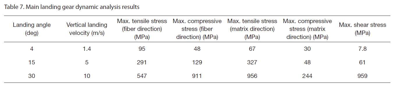
Main landing gear dynamic analysis results
kinetic energy of the vehicle should be absorbed by the landing gear, and allowing the landing gear to undergo a larger compressive force than the vehicle’s weight. The current study investigated the capacity of the landing gear to withstand an unusual landing via a dynamic analysis using LS DYNA, a commercial explicit finite element program.
The landing velocity should be at least larger than the stall velocity. Therefore, the landing velocity was equal to or greater than 60 km/h. It was assumed that a normal landing of the target-drone involves a landing angle of 4 degrees from the ground, as is the case for commercial aircrafts. The vertical landing velocity in this case was equal to 1.4 m/s. To identify the possibility of other landing cases, a dynamic analysis was performed with a vertical landing velocity equal to 5 m/s and 10 m/s, which were equivalent to the landing with landing angles of 15 and 30 degrees, respectively.
The composite panel was modeled using shell elements. Material model number 55 (MAT_055) was used to model the composite materials. The weight of vehicle was simulated by adding a solid box, which is connected to the composite panels, having the same weight as the vehicle. The box was modeled using solid elements. The wheel shaft was modeled as a rigid body. It was fixed while the composite panels and the additional box were initialized with a downward velocity equal to the vertical landing velocity. The finite element mesh of the wheel shaft with boundary conditions is shown in Fig. 14. The maximum tensile and compressive stresses in
the composite panel close to the hole are given in Table 7. Based on our observations, normal landing and landing with an angle of 15 degrees were safe whereas the landing with an angle of 30 degrees yielded a stress level in the composite plies close to their strength.
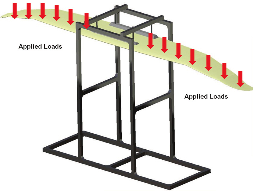
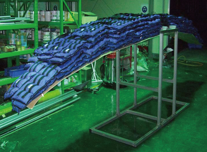
The structural analysis of the wing was verified by a static strength test. Load was applied using sandbags and was gradually increased to a 6g load, as shown in Figs. 15 and 16. The tip displacement was measured as the load increased and to verify the analysis results. The tip displacements
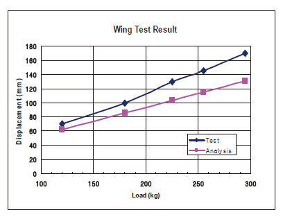
obtained by experiment and analysis are shown in Fig. 17.
The analysis yielded a similar displacement trend as that obtained in the experiment. The deviation between the analysis and experimental results were about 17%. The test displacement was higher than that from the finite element analysis. The authors believed the differences originated from the assumptions on the material properties. The material properties of the composites were tested at the specimen level. A real full scale structure may incorporate a variety of the defects during the manufacturing. Therefore, the structural performance evaluated by the analysis was slightly overestimated the structural performance.
A composite target-drone air vehicle was developed and its structural performance was verified by a finite element analysis and tests. Analysis of the wing included a static strength analysis and examination of buckling. The landing gear was investigated by a dynamic analysis as well as a static strength analysis. The current structural design was verified to be safe in terms of static strength. However, local buckling was predicted in some parts. Analysis results of the wing were verified through a test on a full scale wing and showed a 17% deviation.