The micropump, which is a highly important microfluidic device, has been the subject of several excellent reviews (Laser and Santiago, 2004; Nguyen et al., 2002; Woias, 2005; Zhang et al., 2007). There are several different types of actuation principles for micropumps: piezoelectric, thermopneumatic, pneumatic, electrostatic, electromagnetic, and shape memory alloy. Woias (2005) carefully discussed the strengths and weaknesses of each kind of actuation principle. The micropump’s valve controls the flow in a desired direction and prevents reverse flow. A check valve micropump allows fluid to flow in one direction, whereas an active valve micropump allows the fluid to flow forward or backward through a change in the driving sequence. In spite of its manufacturing complexities, the active valve micropump generally performs well.
In the aerospace applications, Jacot et al. (2001) explained that the pump can be used to control the aerodynamic flow in the boundary layer. For micro aerial vehicles, micropumps can be used for the control of the boundary layer. Also the design principle of micropumps can be applied to micro thruster designs, which are installed in micro satellites.
In a peristaltic micropump, sequential actuations of actuating diaphragms act as valves, causing the fluid to flow in a desired direction. The main advantage of a peristaltic micropump is that no valve or other parts ever touch the running fluid and the actuation is very gentle. Peristaltic micropumps can be used in medical applications, for example, pumping blood through the body during surgery. Smits (1990) presented the first peristaltic micropump containing piezoelectric actuators and pump chambers etched in silicon. When working with water at 100 V and a frequency of 15 Hz, the pump produced a flow rate of 0.1 mL/min and a backpressure of 5.9 kPa. Smits (1990) suggested many attractive uses for peristaltic micropumps, such as the administration of insulin to diabetic patients, chemotherapy for cancer patients, pain relief for terminally ill patients, and the pumping of a coolant in a cooling system.
Several prototypes have been based on the working principle of the peristaltic micropump proposed by Smits(1990). Cao et al. (2001) used microelectromechanical technology in their design and simulation of an implantable medical drug delivery system. They reported that the concept of active, normally closing membrane valves in the peristaltic micropump could prevent backflow. Na et al. (2003) followed the design of Cao et al. (2001) to develop theoretical modeling and fabricate a peristaltic micropump for an implantable medical drug delivery system. Teymoori and Abbaspour-Sani (2004), who also proposed a micropump for drug delivery applications based on peristaltic motion,used the same type of active, normally closing membrane valves as those used by Cao et al. (2001). However, their micropump was designed to satisfy important requirements of a drug delivery micropump as specified in the literature and they used electrostatic actuation. The developed micropump achieved a flow rate of 9 μL/min. Ok and Satoshi (2008) developed another peristaltic micropump with a polydimethylsiloxane (PDMS) pumping body. The PDMS pumping body has several advantages, such as flexibility, a simple and fast fabrication process, and low production cost.Richter et al. (2005) developed a multi-material peristaltic micropump made of a plastic body and metal diaphragm with a piezoelectric actuator. The actuator was economical because it could be mass produced. Doll et al. (2006) developed a high-performance bidirectional micropump for a novel artificial sphincter system; the high backpressure produced by this type of pump can maintain the state of the pressurized inner cuff. Jang et al. (2007), on the other hand, developed a stand-alone peristaltic micropump with a battery-operated driving circuit.
This work reports on the use of a lightweight piezocomposite actuator (LIPCA) (Yoon et al., 2002) and normally closing active membrane valves in the design and fabrication of a peristaltic micropump with a high flow rate and moderate pumping pressure. The active membrane valves were carefully designed so that the chamber possessed a smooth cross section and experienced minimal fluid leakage. Consideration was also given to the power consumption, which was an important factor in the design of microfluidic devices. Our results show that a circular LIPCA with a 0.1 mm thick lead zirconium titanate (PZT) ceramic satisfies the requirements of an optimal actuator design with sufficient actuation displacement.
PDMS is a popular structural material for microfluidic devices because of its high biocompatibility, low cost, transparency, and rapid replicability. The three-dimensional microchannels used in our design can be made easily and rapidly by using a replica molding method (Jo et al., 2000; Kim et al., 2004). Furthermore, instead of using the type of conventional unimorph-type PZT element often found in the literature, we use a miniature circular LIPCA, which can be directly attached to a thin layer of PDMS. In the following sections we explain the design and finite element calculation of the circular LIPCA; we present the detailed design and fabrication of the peristaltic micropump with active membrane valves; and, finally, we discuss our experimental evaluation of the micropump’s performance.
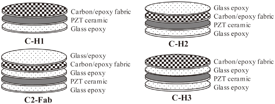
The introduction of the circular miniature LIPCA led to the investigation of several layup sequences of LIPCAs, such as the C-H1, C-H2, C-H3 and C2-Fab sequences in Nguyen and Goo (2006). Figure 1 shows the structure and shape of the designed LIPCAs. In this work, although the layup sequence of the LIPCAs was maintained, the active layer was replaced with a PZT ceramic with a thickness of 0.1 mm and a reduced diameter of 8 mm. This replacement reduced the size, bending stiffness, applied voltage, and power consumption of the actuator. Using the basic properties of the constituent materials of the LIPCAs listed in Table 1, we calculated the coefficient of the unimorph actuator, which is defined as where a is the moment arm and D is the bending stiffness
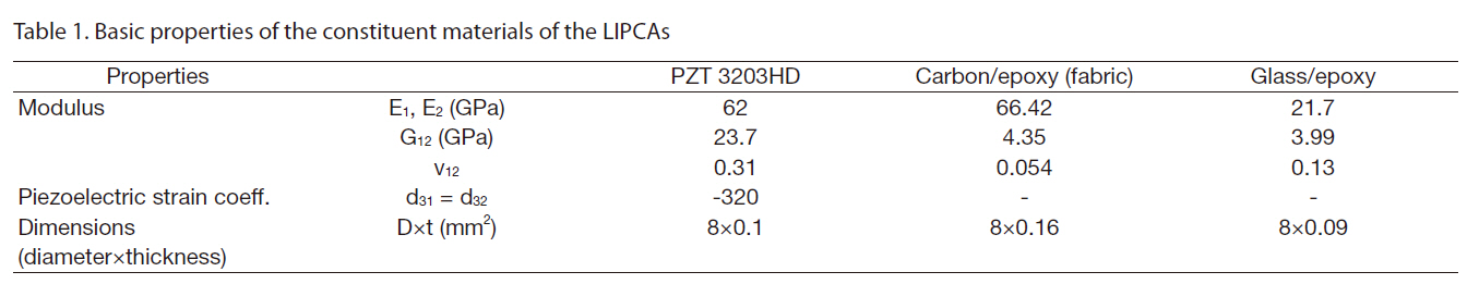
[Table 1.] Basic properties of the constituent materials of the LIPCAs

Basic properties of the constituent materials of the LIPCAs
[Table 2.] Coefficient of the unimorph actuator of the actuator candidates
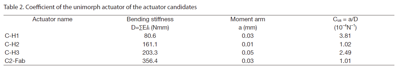
Coefficient of the unimorph actuator of the actuator candidates
(Yoon et al., 2002).Table 2 shows the calculated coefficient of the unimorph actuator. Of the four layup sequences, CH-1 had the largest value, indicating that it can produce the best actuation performance in terms of actuation displacement.
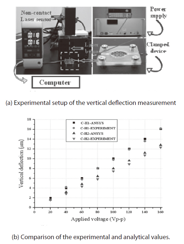
To confirm that CH-1 produces the best actuation performance in terms of actuation displacement, we used ANSYSTM (ANSYS Inc., Canonsburg, PA, USA) to conduct a coupled field analysis of the piezoelectricity and structure. A hexahedral eight-node element solid5 was used to generate the mesh of the PZT ceramic layer, whereas the hexahedral eight-node element solid45 was used to model the carbon/epoxy and glass/epoxy layers. The boundary condition for the simulation was clamped as in the experiment.When an electric field was applied to the active PZT layer, a dome-shaped out-of-plane deflection was induced. The vertical deflection at the center point is shown in Fig. 2b and compared with the experimental results.
As shown in Fig. 2a, the out-of-plane deflection of the fabricated circular LIPCA was measured by means of a noncontact laser sensor (KEYENCE LK-G80; KEYENCE Corporation, Japan), a function generator (Agilent 33120A; Agilent Technologies, Santa Clara, CA, USA), a power supply (Matsusada AMS-1.5B40LC; Matsusada Precision Inc., Tokyo, Japan) and an oscilloscope (Tektroniks TDS 2024; Tektroniks Inc., Beaverton, OR, USA). The experiment was implemented under a clamped boundary condition. The finite element analysis and experimental results are presented inFig. 2b, where it can be seen that the out-of-plane deflection results of the analysis and experiment agree well with one another. The C-H1 layup produced the best actuation displacement, which was the same tendency shown in the cua results in Table 1.
3. Working Principle of a Peristaltic Micropump
Due to its specific working principle, a peristaltic micropump usually requires at least three actuators. The
operation of the peristaltic micropump is based on the upand-down motion of the actuators in different phases. The resultant sequential wave motions can thrust fluid in a desired direction.
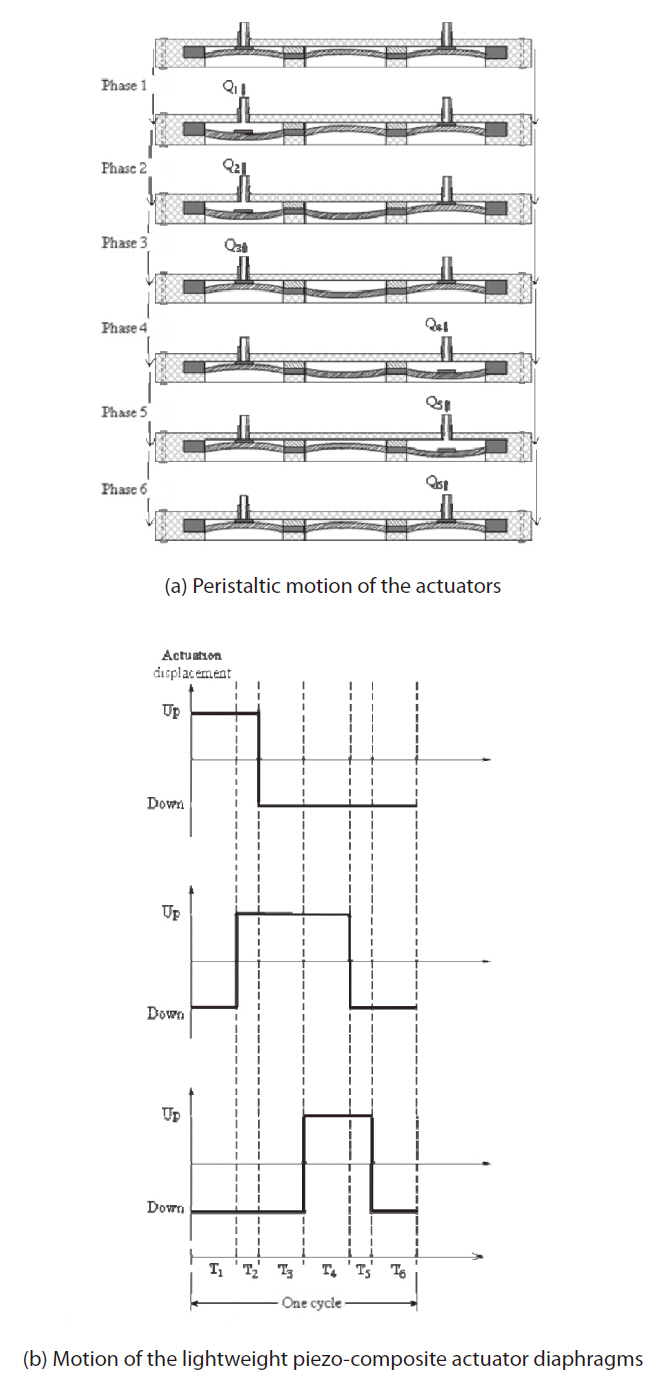
Firstly, a power supply was fabricated. It had a driving circuit that controlled the phases, frequencies and applied voltage of the actuators. To generate the peristaltic motions, we set up a phase scenario of the three actuators as shown in Fig. 3a. In Phase 1, an inlet valve moved down, the inlet was open, and the fluid was then sucked into a pump chamber. In Phase 2, the actuating diaphragm continued moving down and the fluid continued moving into the second chamber. In Phase 3, the inlet valve moved up; this upward movement squeezed the fluid into the second chamber and simultaneously closed the inlet. At this time the pressure in the second chamber became high.
In Phase 4, the outlet valve moved down and the fluid moved to the third chamber. In Phase 5, the actuating diaphragm moved up and the fluid continued thrusting into the third chamber because the inlet valve was closed by that point. In Phase 6, the outlet valve moved up, the fluid flowed out of the outlet, and the outlet closed simultaneously. This completed a cycle of the peristaltic micropump.
Repeated cycles of peristaltic motion forced the fluid into the inlet and eventually pumped the fluid out through the outlet. The motion state of the three actuators is described in Fig. 3b, where we can see that each phase had an interval time of Ti, where i=1, 6, and the summation of the values of Ti,’s where i=1, 6, equals the duration of one cycle.
4. Design of a Peristaltic Micropump with Active Membrane Valves
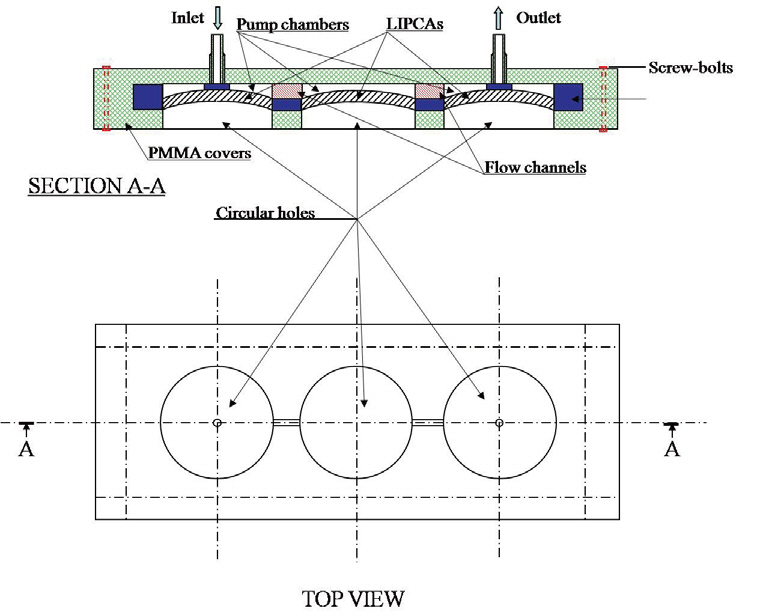
Leakage is a very serious problem concerning the micropump. Leakage causes a reverse flow and reduces the pumping pressure. To avoid leakage, we designed two normally closing active membrane valves at the inlet and outlet as shown in Fig. 4. A PDMS sealing layer was put on the LIPCA to prevent any leakage between the inlet or outlet and the membrane. The active membrane valve was designed to create a smooth flow inside the chambers.
The invented active membrane valve prevented the fluid leakage. It comprised two parts: an actuation membrane
and a sealing layer. The sealing layer was deposited on the surface of the actuation membrane as shown in step (e) of Fig. 5a. The surfaces of the actuation membrane and sealing layer were made of PDMS. This design exhibited several advantages. For example, the fabrication process was easy and the bonding of the components was simple. Moreover, the elastomer sealing layer was compliant and less subject to contact flaws than rigid interfaces (such as a silicone-tosilicone interface). As a result, the design could potentially be applied in areas of biology, medicine, and so on.
5. Fabrication of a Peristaltic Micropump
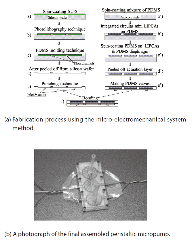
The fabrication process is shown in Fig. 5a. First, a mold of the actuator chamber layer was fabricated, and an SU-8 layer was deposited on a silicon wafer. The thickness of the SU-8 layer was controlled by the spin-coating process. A conventional photolithographic process was used to create the SU-8 pattern on the silicon substrate (as shown in steps (a) and (b) of Fig. 5a). Next, a mixture of the PDMS prepolymer and a curing agent were mixed at an appropriate ratio and stirred. The mixture was then poured onto the mold and softly cured at 65℃ for 45 minutes (step (c) of Fig. 5a). After that, the PDMS actuator chamber layer was peeled off the silicon substrate (step (d) of Fig. 5a). Upon completion of those steps, a punching process was conducted to make the inlet and outlet ports (step (e) of Fig. 5a).
A LIPCA PDMS diaphragm was fabricated. Three circular miniature LIPCAs were integrated on the first thin PDMS layer of 100 μm, which was previously created from a spincoating process (steps (a’) and (b’) in Fig. 5a). The 100 μm PDMS layer was subsequently deposited on the circular miniature LIPCA, and the whole stack was subjected to curing at 65℃ for 45 min (step (c’) of Fig. 5a). An actuation layer was eventually created as shown in step (d’) ofFig. 5a, and the pump chambers were also created when the actuator chamber layer and the actuation layer were aligned and bonded together (step (f ) of Fig. 5a).
Two PDMS layers were bonded to be the main body of the micropump by means of a plasma gent device (Bhattacharya et al., 2005; Satyanarayana et al., 2005), which is an apparatus for creating a perfect bond between PDMS layers or between a PDMS layer and a glass wafer. The top and bottom covers were made out of polymethyl methacrylate (PMMA). The covers were made with a CNC machine (MM-300S), and a pit was created inside the PMMA covers. The main body of the micropump was built tightly inside the rectangular shape of the pit. Note that good bonding of the PDMS layer and the PMMA cover can be achieved by decreasing the proportions
of the pre-polymer and curing agent in the PDMS and increasing the curing temperature (Chow et al., 2006). The inlet and outlet ports were located on the top surface of the PMMA cover. Two plastic piles were used to extend the inlet and outlet ports. The fabricated peristaltic micropump, which is shown in Fig. 5b, had a total size of 28.24 mm ×12 mm × 2 mm.
6.1 Measurement of the pumping performance
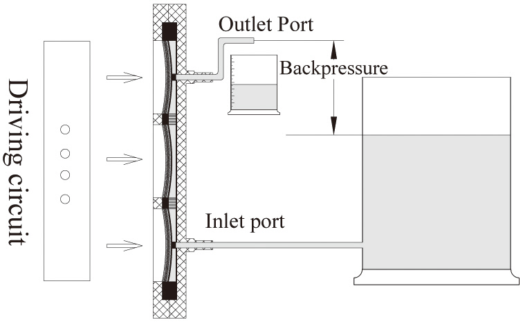
Water was the preferred liquid for measuring the pumping performance. First, the flow rate was measured under various operating conditions including driven voltage, frequency,and backpressure. The flow rate was determined by the weight of the pumped water after a certain time. Fig. 6 illustrates the experimental setup of the flow rate measurement. The backpressure in this experiment was defined as the height difference between the water level in the reservoir and water level at the outlet port. We measured the flow rate for different backpressures by lifting the outlet port. The driven voltage was varied from 20 Vp-p to 160 Vp-p (voltage peak to peak) and the driven frequencies were varied from 10 Hz to 180 Hz.
6.2 Measurement of power consumption
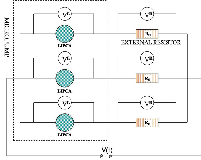
Because the LIPCA is a type of piezoelectric actuator, it can be modeled as an RC circuit (Smith et al., 2007), and the power consumption of the micropump can be measured using the same method as in Smith et al. (2007). Figure 7 shows a schematic of the experimental power consumption measurement. The measurement system consisted of the peristaltic micropump, three external resistors, a power supply, and an oscilloscope (Tektronix TDS 2024; Tektroniks Inc.). Each LIPCA is attached in series to a 10 kΩ external resistor, and the voltage of each external resistor was monitored to determine the current, which is expressed as follows:
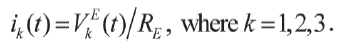
The applied voltage, V(t), was imposed upon each LIPCA and external resistor series. The phase difference of the applied voltage among the three actuators was 120 degrees. In addition, the applied voltage was changed from 20 Vp-p to 160 Vp-p and the driven frequencies were varied from 10 Hz to 160 Hz. While the peristaltic micropump was working with the water fluid, the voltage over each LIPCA, VLk(t), and the voltage over each resistor, VEk(t), were recorded into the memory of the oscilloscope. The power consumption of the peristaltic micropump can be calculated as follows by summing the power consumption of each LIPCA as
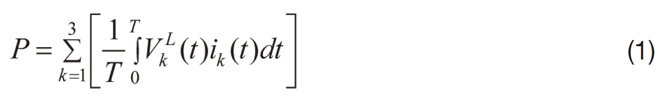
where T is a period.
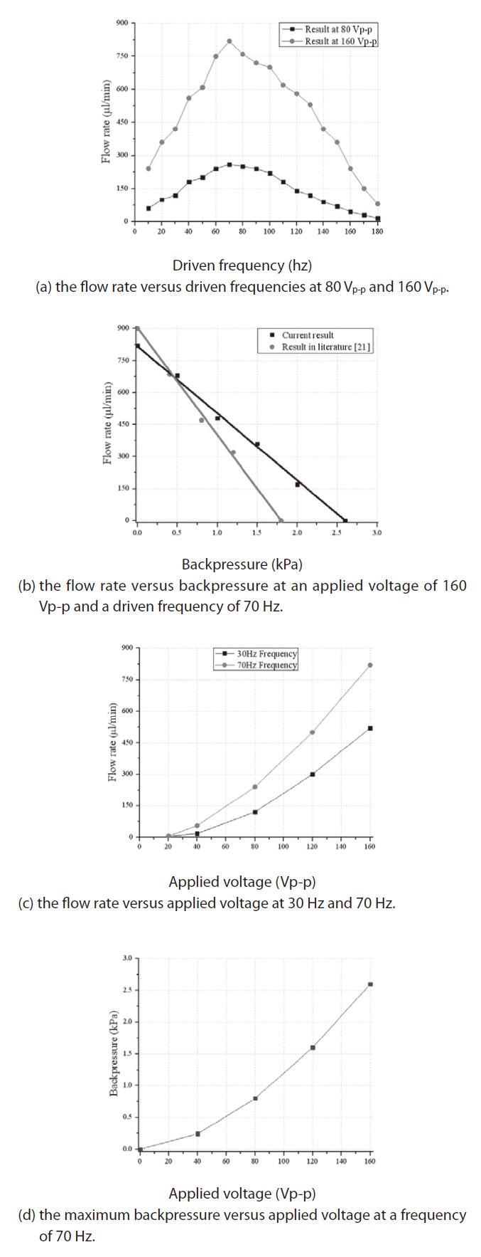
Figure 8a shows how the flow rate varied in relation to a driven frequency range of 10 Hz to 180 Hz. At a frequency of 70 Hz, the maximum flow rate was 820 μL/min for an applied voltage, 160 Vp-p, and 260 μL/min for an applied voltage of 80 Vp-p. Before the resonance frequency, the flow rate increased as the frequency increased; after the resonance frequency, the flow rate decreased as the driven frequency increased. It is clear that 70 Hz is the resonance frequency of the peristaltic mircopump, and at this frequency the actuator membranes reach the maximum out-of-plane deflection, thereby causing the maximum stroke volume and the maximum flow rate. When the driven frequency increased beyond the resonance frequency, the out-of-plane deflection of the actuator membrane decreased because the membrane deflection could not follow the fast change that occurred in the applied voltage at a high frequency. As a result, the flow rate decreased.
Figure 8b shows how the flow rate varied in relation to the backpressure. When the flow rate was 0 μL/min, the maximum backpressure was 2.6 kPa; and when the maximum flow rate was 820 μL/min, the backpressure was 0 kPa. The backpressure achieved with this design was better than the backpressure achieved with the micropump in our previous work (Nguyen et al., 2008). This improvement is most likely due to the fact that the active membrane valves on the PDMS sealing layer reduced the fluid leakage. Note also that a backpressure of 0 kPa has no physical meaning in real applications. However, the line connecting the zero backpressure point and the zero flow rate point indicates the boundary of the operating region. We can therefore choose any point inside the line as an operating point.
Figure 8c illustrates how the flow rate varied in relation to the applied voltage. Because we used a PZT thickness of 0.1 mm, we limited the maximum voltage to 160 Vp-p to avoid the domain switching phenomenon.
Figure 8d shows the relation between the pumping pressure and the applied voltage. After testing the backpressure at various applied voltages, we found that the micropump exhibited a maximum backpressure of 2.6 kPa at 160 Vp-p and 70 Hz.
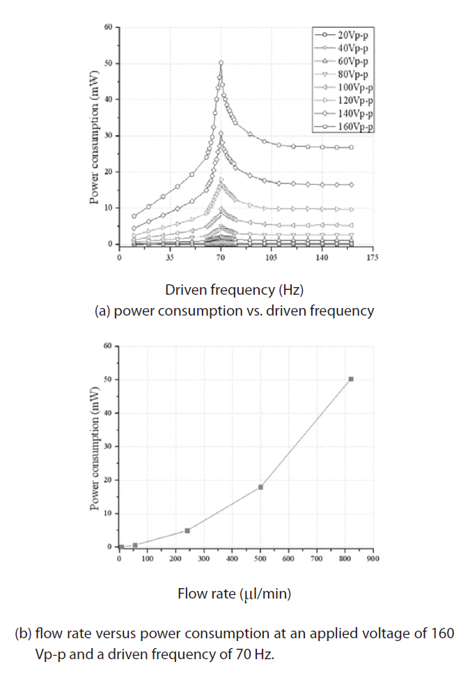
Figure 9 shows the power consumption results of the present peristaltic micropump with respect to the driven frequency and flow rate. Figure 9a, which describes the power consumption variation with respect to the driven frequency, was studied for voltages ranging from 20 Vp-p to 160 Vp-p. The maximum power consumption was reached at a driven frequency of 70 Hz because the micropump system was resonant at 70 Hz. At this point, the micropump generated its maximum external work and the power consumption was maximized due to the energy conservation. Figure 9b shows that the power consumption increased rapidly when the flow rate increased and that the maximum power consumption of 50.9 mW was achieved at 820 μL/min.
The peristaltic micropump reported by Na et al. (2003) had a pump size of 70 mm × 35 mm, a flow rate of 11.4 μm/min, and a backpressure of 351.1 Pa at 130 V and 4 Hz. The multimaterial peristaltic micropump, which comprised a plastic body and a metal diaphragm with a piezoelectric actuator, produced a water flow rate of 150 μm/min (Richter et al., 2005). The peristaltic micropump of Doll et al. (2006) has a package size of 30 mm × 11 mm ×1 mm, a flow rate of 1.8 mm/min, and a backpressure of 60 kPa at high voltages ranging from -100 V to 250 V when boosted by a battery. The peristaltic micropump presented by Jang et al. (2007) had a package size of 75 mm × 21 mm × 1.1 mm, a flow rate of 36.8 μm/min, a backpressure of 520 Pa, and a power consumption of 683 mW at 100 Vp-p and 700 Hz. The present peristaltic micropump had a package size of 28.24 mm × 12 mm × 2 mm, a flow rate of 820 μm/min, a backpressure of 2.6 kPa, and a power consumption of 51 mW at 160 Vp-p and 70 Hz.
When comparing the performance of micropumps, we needed to consider such factors as the diaphragm material, the diaphragm thickness, the package size, the working fluid, the applied voltage, the driven frequency, the backpressure,and the the flow rate (Laser and Santiago, 2004). The performance of the present micropump in terms of flow rate and backpressure provides suitable qualifications for medical and engineering applications.
Video clips of the experiment can be found on Youtube (http://www.youtube.com/watch?v=TVOqCr6XMu0, http://www.youtube.com/watch?v=JAqCZzv4szs, http://www.youtube.com/watch?v=u5xtUA7Ik4k). It shows the water column continuously rising, indicating that the flow is stable. Even though several air bubbles formed in the beginning, small bubbles moved through the pump chamber after a steady flow was reached.
This paper reported the development of a peristaltic micropump with smart active membrane valves. The micropump possessed three miniature circular LIPCAs and two active membrane valves. The valves reduced the reverse flow and improved the pumping pressure characteristics.The micropump achieved a pumping pressure of 2.6 kPa and a flow rate of 820 μL/min at 160 Vp-p and 70 Hz. In comparison to the pumping performance of a piezo-based peristaltic micropump, the present micropump exhibited a higher flow rate and a more moderate pumping pressure.