The effects of swirl chamber’s diameter and length on injector’s dynamic characteristics were investigated through an experimental study. A mechanical pulsator was installed in front of the manifold of a swirl injector which produces pressure oscillations in the feed line. Pressure in the manifold, liquid film thickness in the orifice and the pressure in the orifice were measured in order to understand the dynamic characteristic of the simplex swirl injector with varying geometry. A direct pressure measuring method (DPMM) was used to calculate the axial velocity of the propellant in the orifice and the mass flow rate through the orifice. These measured and calculated values were analyzed to observe the amplitude and phase differences between the input value in the manifold and the output values in the orifice. As a result, a phase-amplitude diagram was obtained which exhibits the injector’s response to certain pressure fluctuation inputs. The mass flow rate was calculated by the DPMM and measured directly through the actual injection. The effect of mean manifold pressure change was insignificant with the frequency range of manifold pressure oscillation used in this experiment. Mass flow rate was measured with the variation of injector’s geometries and amplitude of the mass flow rate was observed with geometry and pulsation frequency variation. It was confirmed that the swirl chamber diameter and length affect an injector’s dynamic characteristics. Furthermore, the direction of geometry change for achieving dynamic stability in the injector was suggested.
Liquid rocket engines operate using combustors in which high pressure combustion processes are performed. This fact led the liquid rocket engine to have a great demand for combustion stability. Due to the great demand, many research have been done on combustion instability since the 1940s. Despite the large amounts of human and financial resources invested on the research, the combustion instability remains as an unsolved problem since it is a very complicated process that involves many physical phenomena. Efforts have been made for suppressing the symptoms associated with combustion instability as well as for revealing the causes of the combustion instability. Such efforts resulted as the baffle which is a additional structure installed in the combustion chamber to suppress the combustion instability. It was developed in the United States and has been used widely in their engines. In Europe, a Helmholtz resonator attached to the combustor was employed (Bazarov, 1979, 1995, 1996; Bazarov and Yang, 1998; Rubinsky, 1995).
However, these additional structures mean additional mass which is a critical disadvantage in liquid rocket engines. Furthermore, the additional mass negatively affects combustion efficiency.
Researchers in Russia, where the swirl type injectors are used, attempted to suppress combustion instability by modifying the injectors. The researchers were able to eliminate combustion instability without adding structures. The study for this method is called injector dynamics.
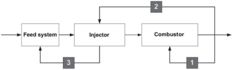
Injector dynamics is a study that focuses on the dynamic responses of the injector to dynamic disturbances (Bazarov, 1979; Bazarov and Yang, 1998). Figure 1 is a schematic of dynamic interactions among three elements in a rocket engine system: the feed system, injector, and combustor. The propellant flows through the feed system to the injector, and is injected into the combustor by the injector. During combustion, pressure oscillation is generated, affecting the subsequent combustion process (Loop1). The acoustic pressure oscillation causes fluctuations in the injector’s properties, such as propellant velocity, pressure in the orifice and the mass flow rate (Loop2). Furthermore, the oscillation in the injector excites the pressure in the feed system (Loop3). Thus, the whole rocket engine system can become dynamically unstable due to these dynamic interactions,which translated into combustion instability. However, the injector acts as a bridge between the feed system and the combustor. If the injector does not respond to the dynamic disturbances entering it, then the injector can suppress combustion instability by cutting the dynamic interaction loops. This is the motivation of the injector dynamics.
To use the injector’s dynamic characteristics acquired by the injector dynamics study, a transfer function must be derived, providing the ratio between the input and output of the injector. Thus, a mechanical pulsator was built for the experiment in order to generate sinusoidal input oscillations. Additionally, DPMM was developed to acquire the output data. Experiments on a simplex swirl injector were conducted followed by results analysis (Khil et al., 2009).
This study focused on the influence of an injector’s geometrical variations on the injector’s dynamic characteristics.
2. Transfer Function of a Swirl Injector
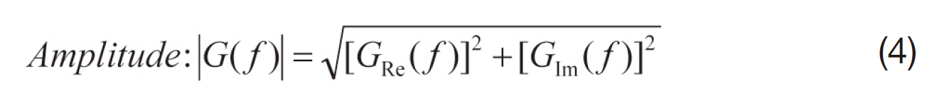
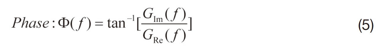
A transfer function is a mathematical representation, in terms of spatial or temporal frequency, of the relation between the input and output of a system. In this study, the input was the pressure fluctuation of the feed system or manifold, and the output was the mass flow rate fluctuation. The time-domain input and output were converted into the frequency-domain with the fast Fourier transform. The transfer function of the injector was:


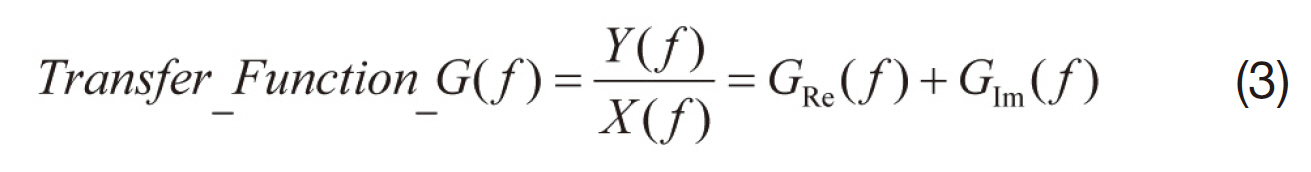
From the transfer function, amplitude and phase were calculated.
In the injector dynamics study, the transfer function of each element or parameter was derived separately and then combined to obtain the whole transfer function of the injector. The theoretical derivation of the whole transfer function of the injector was conducted by Bazarov (1979). Further experimental work for the completion of the transfer function of an injector must be completed.
3. Elements of a Typical Simplex Swirl Injector
The swirl injector is a widely-used type of atomizing device. It is commonly used in aviation engines and combustion chambers of high-pressure, high-temperature power systems. The schematic of swirl injectors can be reduced to a set of three elements as represented in Fig. 2: the tangential
entries, the swirl chamber and the orifice. A tangential entry supplies the injector propellant with initial tangential velocity. The Swirl chamber develops the swirling motion of the propellant. The orifice accelerates the propellant in order to generate a thin cone-shaped film (Bazarov, 1979).
In this study, the swirl chamber was designed to be replaceable to see the effect of its geometry on the simplex swirl injector’s dynamic characteristics.
The injector used in this study was a simplex swirl injector. The length and diameter of the swirl chamber were designed with the capability of being varied. Two electrodes were installed at the orifice in order to acquire liquid film thickness through an electrical conductance method. A 10 V AC voltage with the frequency of 10 kHz was generated with a function generator. The voltage variation between the electrodes was recorded by the computer in real time. The experimental apparatus is shown inFig. 3. The reference electrodes were installed to compensate for the electrical conductivity change due to the temperature.
The diameter and length of swirl chamber were varied as a means for observing the influence of these variations on a simplex swirl injector’s dynamic characteristics. As shown in Table 1, the diameter of the swirl chamber was changed from 12 mm to 24 mm with an interval of 3 mm while the length of the swirl chamber was fixed at 19 mm. The length of the swirl chamber was changed from 19 mm to 55 mm with an interval of 9 mm while the diameter of the swirl chamber remained fixed at 18 mm.
Manifold pressure of 4, 5, 6 bar were tested for every geometry of the injector within a frequency range of 5~25 hz. The testing manifold pressure was chosen to be relatively low in comparison to a practical injector because the injector was made of acryl to insulate the electrode from the injector. Since the result indicated that the effect of manifold pressure change was small in the testing frequency
[Table 1.] Experimental conditions
Experimental conditions
region, this manifold pressure range was appropriate for the experiment.
The pressure in the orifice and liquid film thickness were measured during the experiment and mass flow rate through the orifice was calculated using DPMM with the data obtained above (Khil et al., 2009).
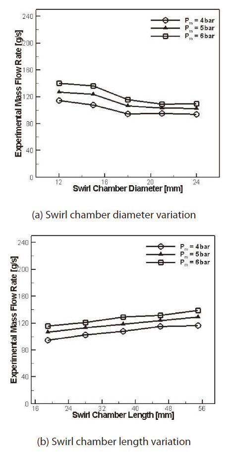
The mass flow rate values of the injectors with swirl chamber diameter variation and swirl chamber length
variation are given in Fig. 4. The mass flow rates were directly measured in the experiment.
The mass flow rate decreased by approximately 20g/s within the 12 mm increase of swirl chamber diameter. This tendency was witnessed throughout the manifold pressure change.
The discharge coefficient μ, which plays a dominant role in determining the mass flow rate, was calculated as follows (Borodin et al., 1967; Kulagin and Moroshkin, 1966).
C and b are constant values, and A is the Abramovich geometrical characteristic of the swirl injector.
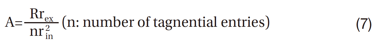
Through these equations, the mass flow rate decreased with the increase of A which was proportional to the swirl chamber diameter. Physically, this was due to the higher swirl action which enlarges the air core diameter and thereby reduces the effective flow area of the orifice (Rizk and Lefebvre, 1985).
The mass flow rate increased by approximately 20g/s within the 36 mm increase of swirl chamber length. This tendency was also exhibited throughout the manifold pressure change.
As shown in Fig. 5, Rizk and Lefebvre (1985) stated that the effect of the swirl chamber length on mass flow rate was small due to relatively small frictional losses. However, since the interval of the swirl chamber length variation was much larger in this paper, the mass flow rate change was more apparent.
Such dependence of the mass flow rate on the swirl chamber length and diameter was also described through experimental data in studies produced by Khavkin (2004).
A phase-amplitude diagram of the mass flow rate through the orifice with varying manifold pressure is shown in Fig.6. It was one case of the geometry variation in which the swirl chamber diameter was 18 mm and length was 19 mm.As shown in the figure, each lines standing for different manifold pressure are depicted similarly. This indicates that the effect of manifold pressure on injector’s dynamic characteristic with the pulsation frequency range of 5~25 hz was insignificant. This result coincides with the result obtained by Khil et al. (2010), who investigated the dynamic characteristic of a simplex swirl injector. The work showed that the dynamic characteristics of the simplex swirl injector varied by manifold pressure in the pulsation frequency region of over 100 hz.
This tendency was exhibited for the remaining eight geometries, indicating that the effect of manifold pressure was also insignificant even with variations in the swirl chamber’s length or diameter.
5.3 Frequency-amplitude effect
The effect of input pulsation frequency on the mass flow rate pulsation amplitude of injector was observed. The amplitude of the mass flow rate pulsation is an important parameter because it serves as the criterion for dynamic stability of the injector. If the amplitude of the mass flow rate is small, then stable injection of the propellant is viable. Stable injection refers to a damper-like injector in the dynamic interactions among three elements of the rocket engine system, as mentioned in the introduction. Thus, a dynamically stabilized rocket engine system is free of combustion instability and can be operated with high
[Fig. 6.] Phase-amplitude diagrams of mass flow rate with swirl chamber diameter 18 mm length 19 mm.

reliability. Thus, minimizing the amplitude of the mass flow rate pulsation is a key goal of this study.
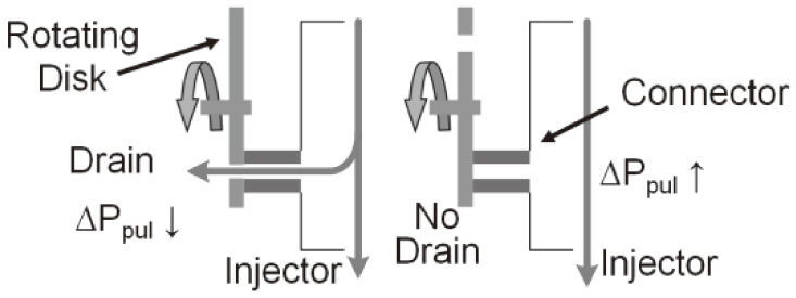
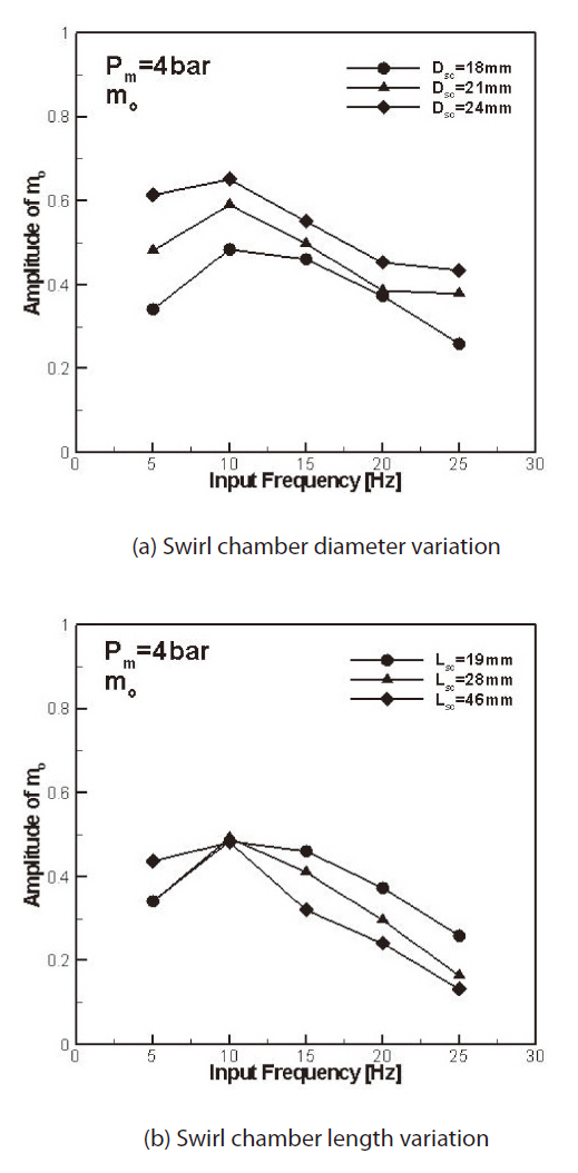
Three samples for each parameter of the injector geometry were chosen for detailed study. The frequency-amplitude diagrams of the injectors with different geometries are given. The amplitudes decreased as the input pulsation frequency increased. This is caused by the shorter coincidence duration time of the rotating disk hole and the connector hole in the hydrodynamic mechanical pulsator by a quickened rotating speed when the pulsation frequency was high. Fig.7 illustrates this mechanism of the pulsator.
In Fig. 8a, the amplitude decreased as the swirl chamber diameter decreased. In Fig. 8b, the amplitude decreased as the swirl chamber length increased. As shown in previous section, a smaller swirl chamber diameter and longer swirl chamber length indicates a larger mass flow rate, which again translates into higher momentum. Higher momentum element requires higher energy to change its direction or speed, which makes the element insensitive to a disturbance. Thus, the smaller swirl chamber diameter injector and longer swirl chamber length injector possessed smaller mass flow rate pulsation amplitude with the same input pulsation as the other injectors.
The dynamic characteristics of a simplex swirl injector with varying geometries were investigated.
The effect of the input pressure in the manifold was insignificant under the frequency range of 5~25 hz. Only minor differences were observed in the injector’s dynamic characteristics.
The mass flow rate of the injector increased as swirl chamber diameter decreased and as the swirl chamber length increased.
The phase of the mass flow rate pulsation, which was designated as the output pulsation, moved clockwise in the phase-amplitude diagram, indicating that the pulsation of the mass flow rate became faster as the input pulsation frequency increased.
The amplitude of the mass flow rate pulsation decreased with the decrease of swirl chamber diameter and with the increase of swirl chamber length indicating that an injector with a smaller swirl chamber diameter and longer swirl chamber length was dynamically more stable and was better for combustion stabilization in a liquid rocket engine.