When a structure is loaded by periodic constant loads or thermal loads, it will experience elastic strain as well as creep strain.
The creep phenomenon was first considered in the 1920s during the analysis of metal under high thermal loads.Since then, creep phenomenon has undergone extensive research from the 1950s-1960s until present-day. In addition to theoretical results, experimental evidence has proven the existence of creep strain and its effect on material strain(Iliushin and Ogibalov, 1966; Iliushin and Pobedrya, 1970;Malmeiter et al., 1980; Rabotnov, 1966, 1998; Rjanhixin,1968). In creep research, function of time is often used. If we consider v(τ), in which τ∈(-∞,
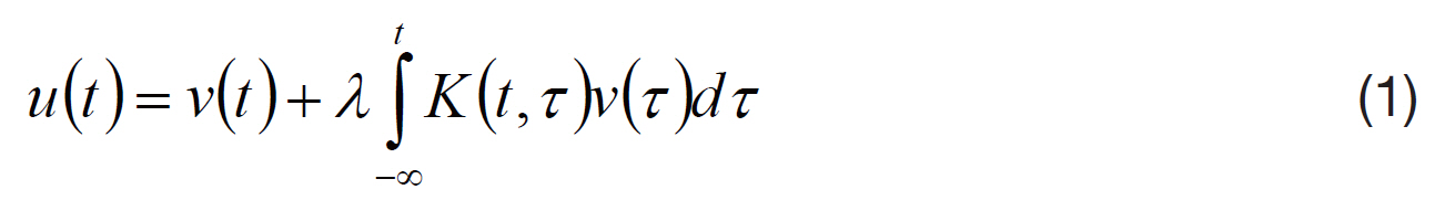
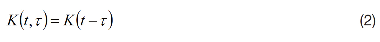
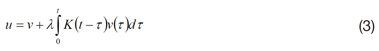
In Eq. (1), the lower limit of the integral is -∞, but in fact,any history of F starts from a certain point: the beginning of materials manufacturing, or the beginning of the loading process. Thus, Eq. (1) can be rewritten as:
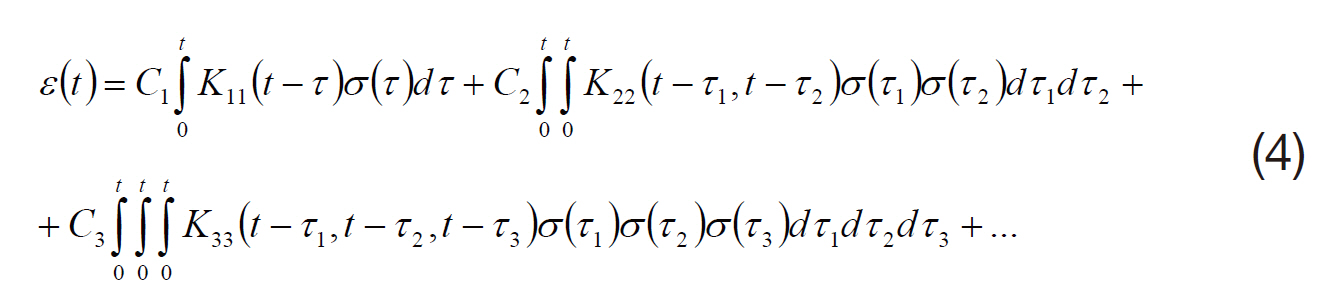
In the simplest case(one dimension), the nonlinear stress-strain relationship can be expressed as (Grin and Adkinc, 1985):
In the tensor form (Grin and Adkinc, 1985):
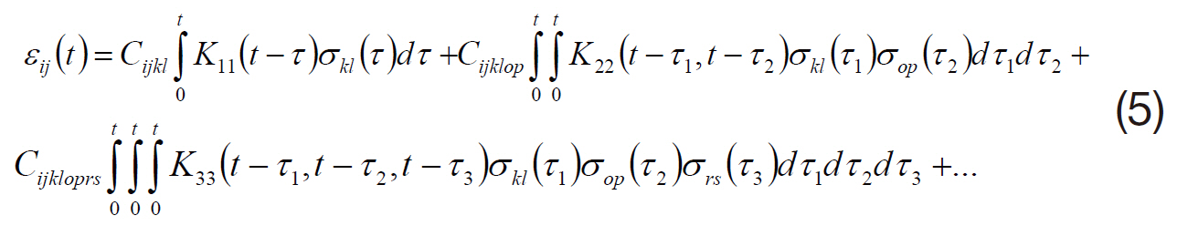
The multiple term in Eq. (5) has the following form (Grin and Adkinc, 1985; Malmeiter et al., 1980):

For anisotropic materials, the general stress-strain relationship is as follow (Iliushin and Ogibalov, 1966; Iliushin and Pobedrya, 1970; Malmeiter et al., 1980; Rabotnov, 1966,1998; Rjanhixin, 1968):
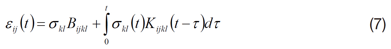
Eq. (7) is Hooke’s law for viscoelastic materials. Here the Bijkl and Kijkl (t-τ) are obtained from experiments.
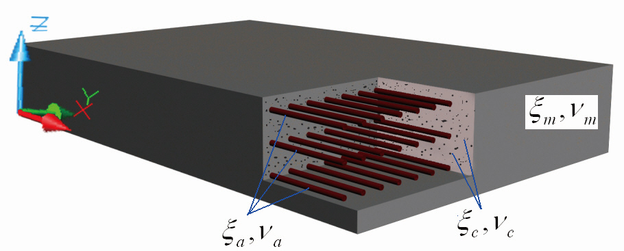
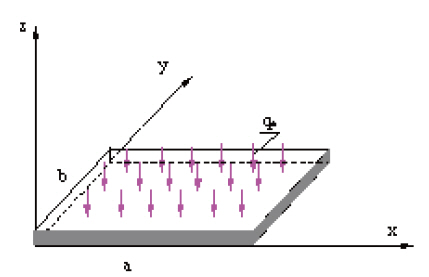
Consider a plate made of a 3-phase composite Fig. 1.
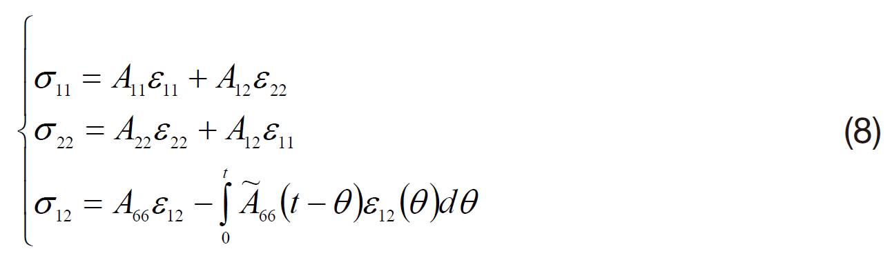
Experimental results indicate that creep strain is notable only under the action of shear stress (Malmeiter et al., 1980),then Eq. (7) can be written in the following form:
he function A?66(
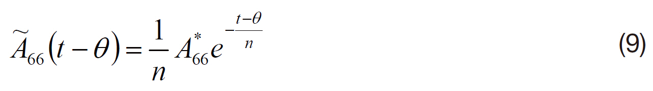
Here A*66 and n are obtained from experimental tests; n is the stretch coefficient of the material.
2. Bending Equation Considering Creep Effect
The research of the effect of each phase (fiber, particle)on the bending of a 3-phase composite plate was conducted by Dinh and Pham (2009a). Nguyen and Dinh (2010)investigates the bending of a 3-phase composite plate when the shear effect is taken into account.
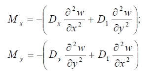
In the making of the bending equation, the plate’s bending moment was determined by Malmeiter et al. (1980):
Creep appears within the twist moment:
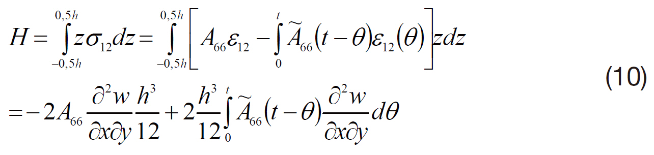
Where:
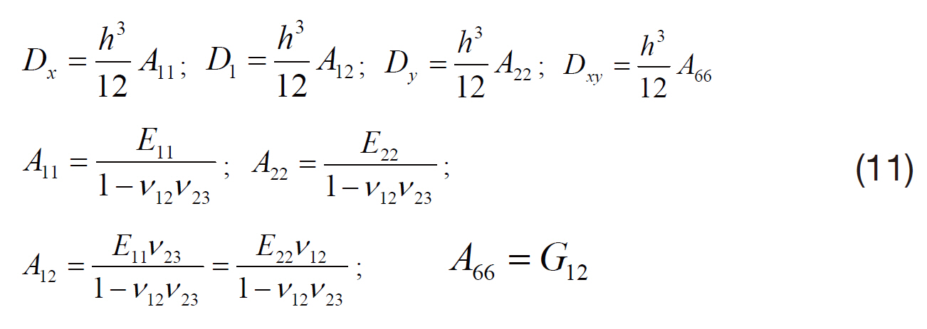
In Eq. (11), the elastic modules of the 3-phase composite were completely determined as in Dinh and Pham (2009b).By introducing Eqs. (10) and (11) into the equilibrium equation:
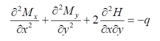
we obtain the plate’s deflection equation when creep strain is taken into account:
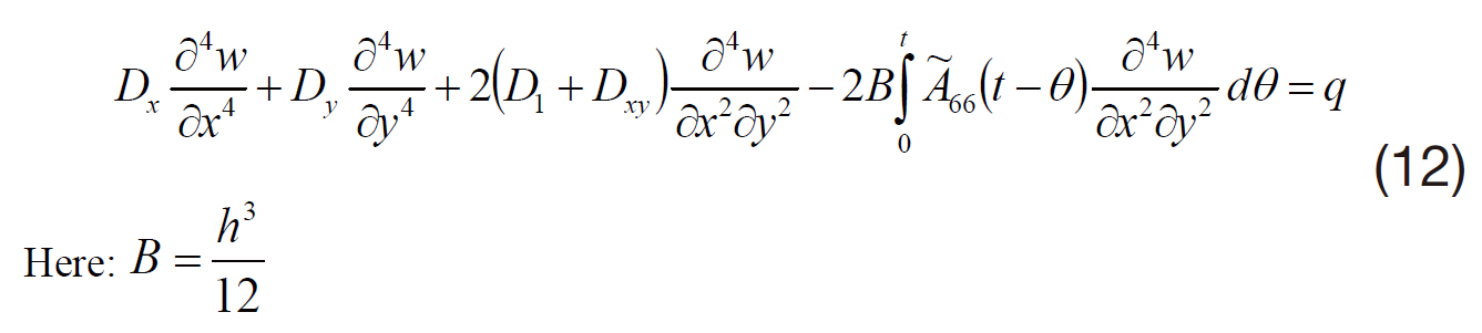
We considered a square three-phase plate of size a×b consisting of fibers reinforced along the x axis. The plate had thickness to aspect ratio
The root of Eq. (12) is:
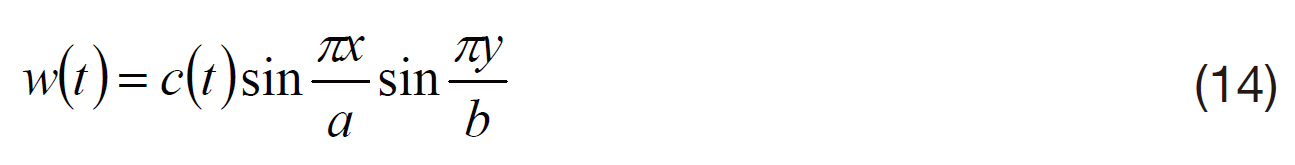
From the boundary conditions:
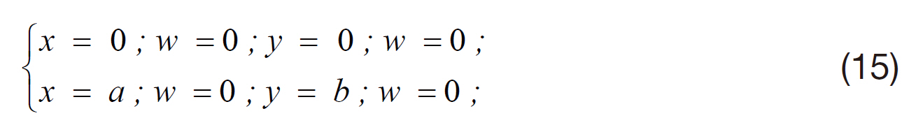
Considering the following relationship:
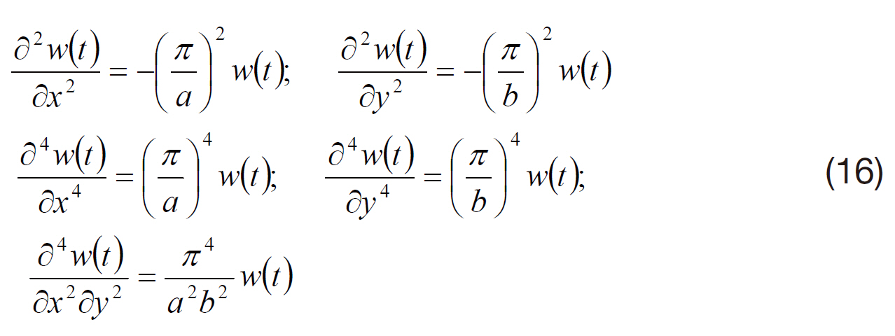
By introducing Eqs. (14-16) into (12), we obtain the equation for the deflection c(t) of the plate’s central point,which is a function of time t:
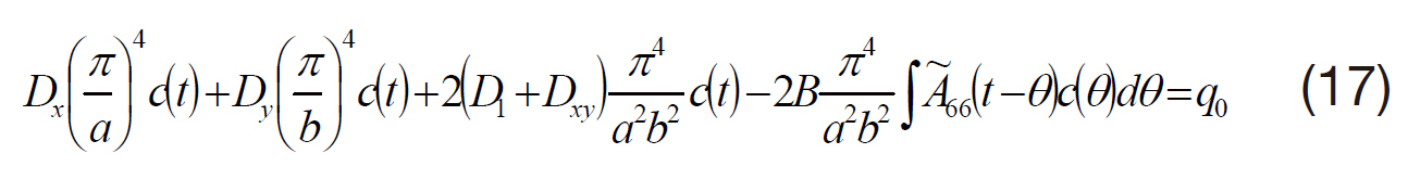
In abbreviate form, Eq. (17) becomes:
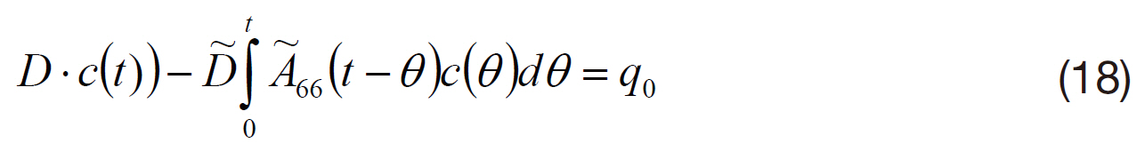
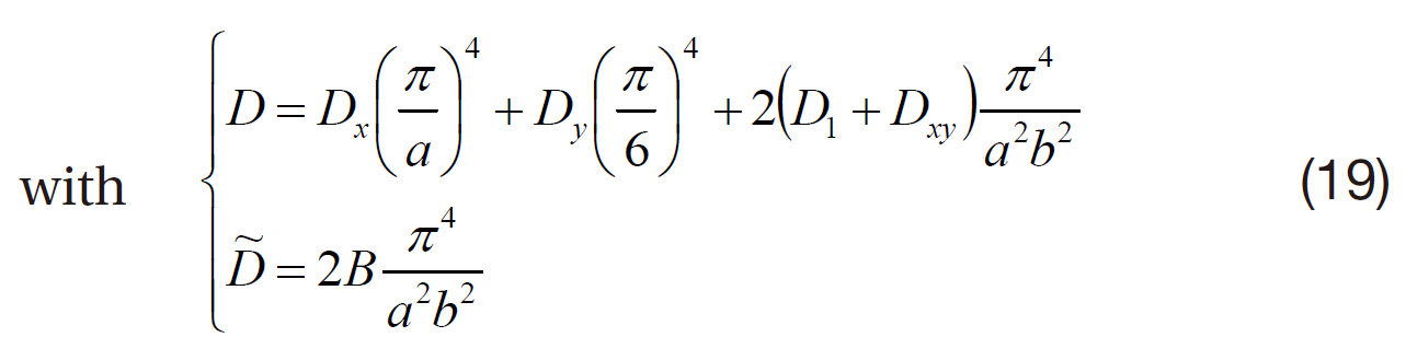
To solve Eq. (18) we need to know of
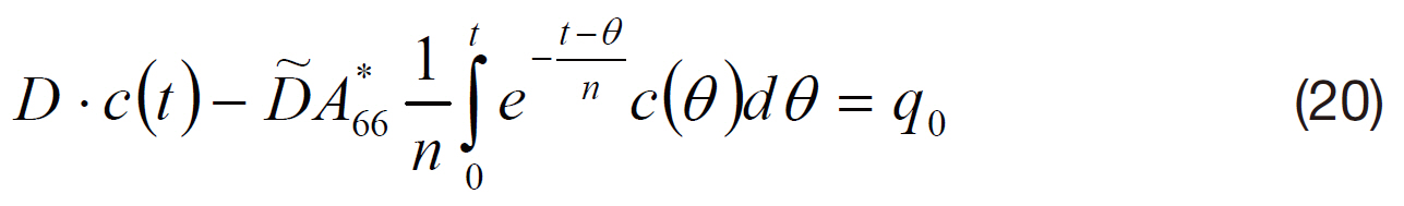
Notice that the term under integral in Eq. (20) has the form :
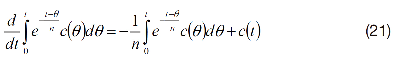
Differentiating both sides of Eq. (21) with respect to t:
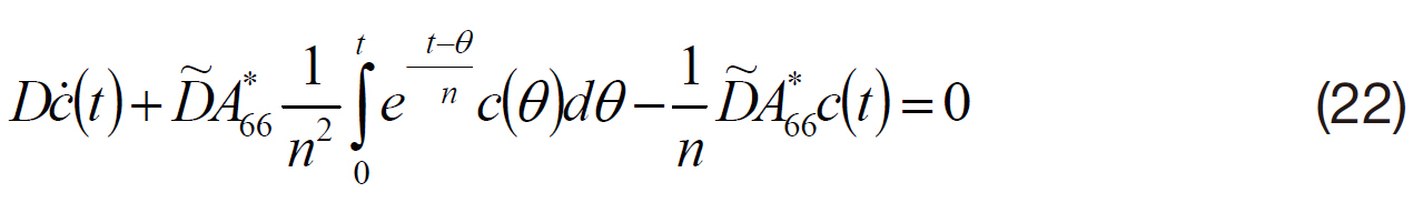
From Eq. (20) and Eq. (22) we have:
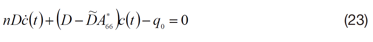
The condition for initial elasticity:
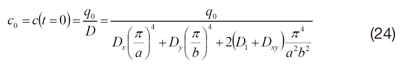
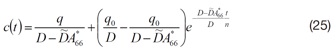
The root of Eq. (23) can be expressed as:
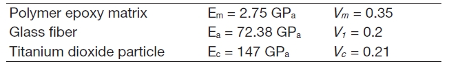
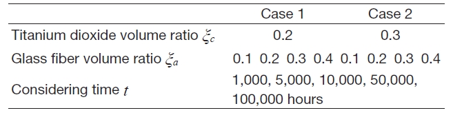
Consider a 3-phase composite plate having the following properties:
The deflection
[Table 1] Creep displacement (mm) of a 2-phase polymer composite (without added particle)
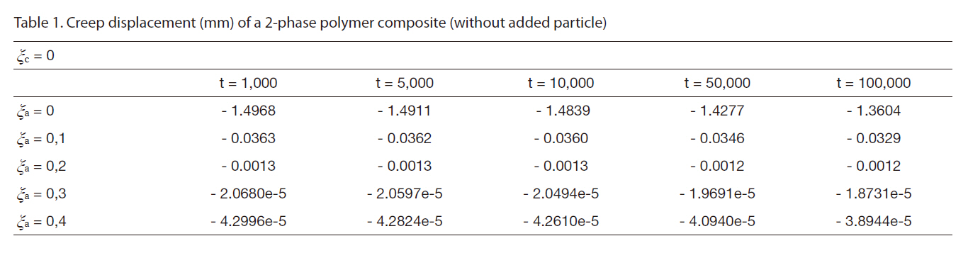
Creep displacement (mm) of a 2-phase polymer composite (without added particle)
[Table 2] Creep displacement (mm) of a 2-phase polymer composite (particle volume ratio is 5%)
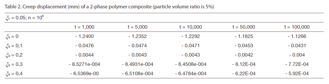
Creep displacement (mm) of a 2-phase polymer composite (particle volume ratio is 5%)
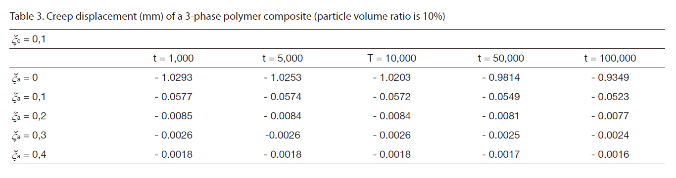
[Table 3] Creep displacement (mm) of a 3-phase polymer composite (particle volume ratio is 10%)

Creep displacement (mm) of a 3-phase polymer composite (particle volume ratio is 10%)
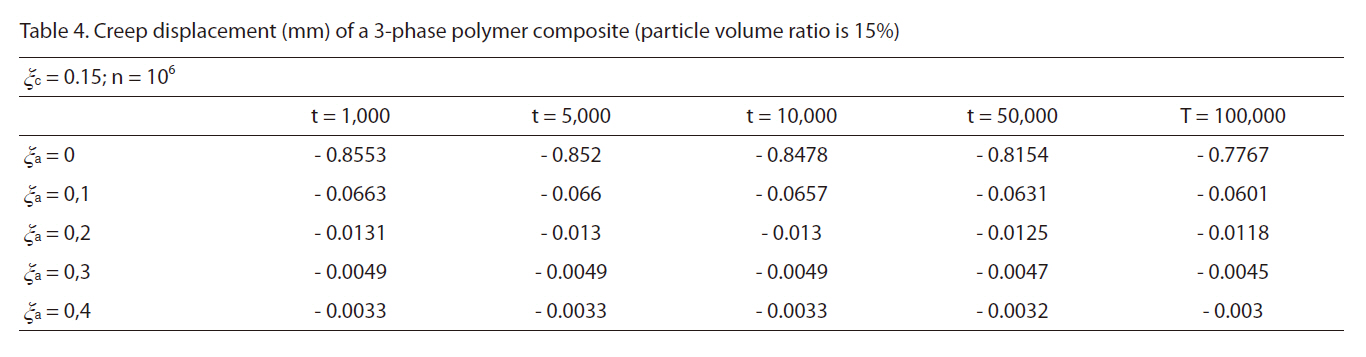
[Table 4] Creep displacement (mm) of a 3-phase polymer composite (particle volume ratio is 15%)

Creep displacement (mm) of a 3-phase polymer composite (particle volume ratio is 15%)
[Table 5] Creep displacement (mm) of a 3-phase polymer composite (particle volume ratio is 20%)
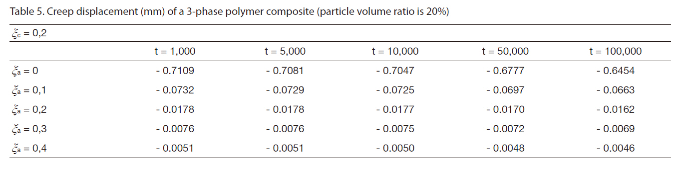
Creep displacement (mm) of a 3-phase polymer composite (particle volume ratio is 20%)
A*66 and
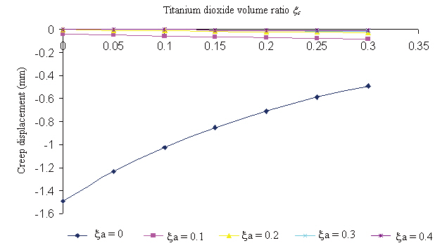
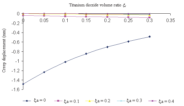
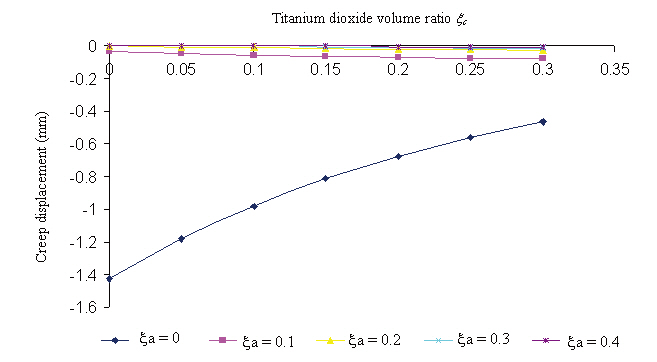
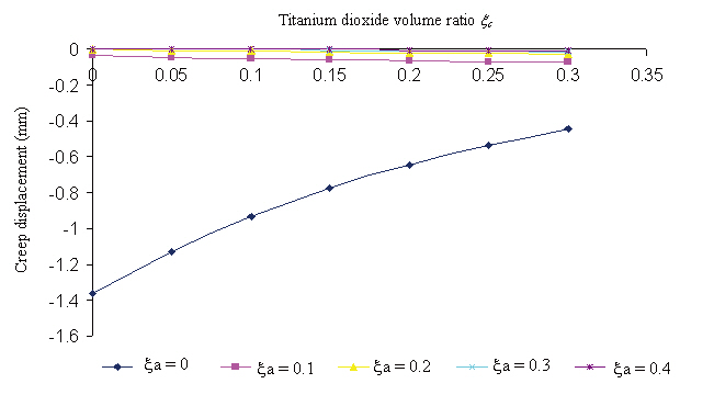
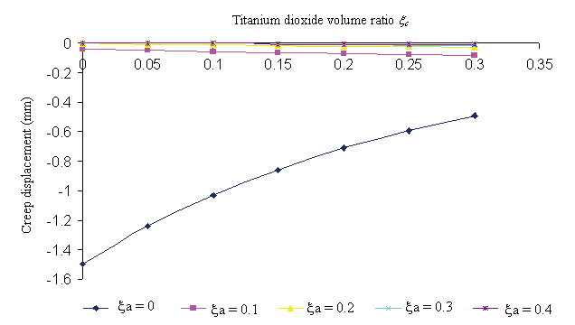
Creep displacement of a 3-phase polymer composite depend on particle volume ratio and time (1,000 hour, 5,000 hour, 10,000 hour, 50,000 hour, 100,000 hour) presented in Fig. 3 - Fig. 7
[Table 6] Creep displacement (mm) of a 3-phase polymer composite (particle volume ratio is 25%)
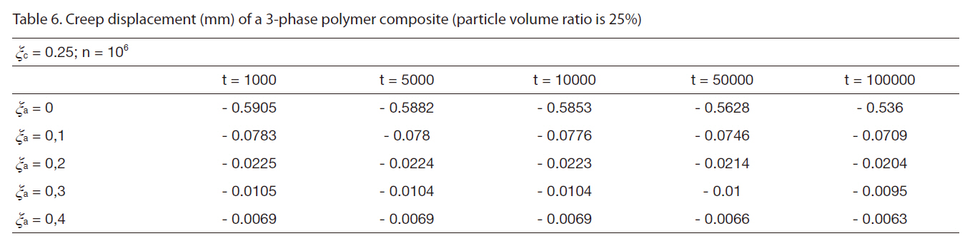
Creep displacement (mm) of a 3-phase polymer composite (particle volume ratio is 25%)
[Table 7] Creep displacement (mm) of a 3-phase polymer composite (particle volume ratio is 30%)
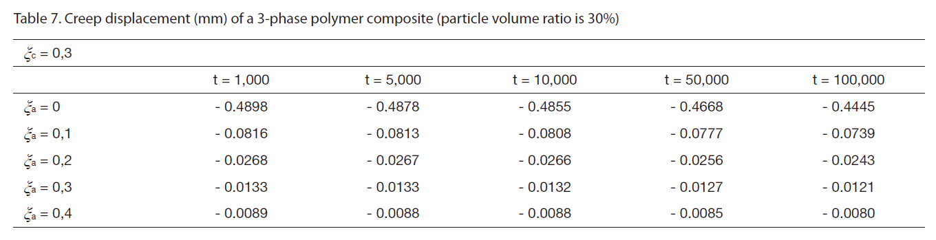
Creep displacement (mm) of a 3-phase polymer composite (particle volume ratio is 30%)
Creep displacement of a 3-phase polymer composite depend on particle volume ratio and time (1,000 hour, 5,000 hour, 10,000 hour, 50,000 hour, 100,000 hour) presented in Figs. 3-7.
In this paper, we researched the bending of a 3-phase composite plate in which creep was taken into account.The deflection equation was obtained for a composite plate possessing the creep effect.
From the analysis of the 3-phase composite plate consisting of a polymer matrix, glass fiber and titanium dioxide, the following conclusions were produced:
- The creep strain of the 3-phase composite plate considered in this research is not significant.
- The creep strain causes the plate to shrink, indicating that the plate’s bending deflection was reduced.
- Changes in the volume ratios of the fiber and particle components can lead to changes in the creep strain of the plate in bending. The creep strain of plate will reduce if the volume ratios of the fiber component in composite increases.