Activated carbon fiber(ACF) has narrower pore distribution and the micro-pore opening locates on the external surface of fiber. Therefore, it displays faster adsorption dynamics than commercial activated carbons because it shortens the molecular diffusion path inside the fiber [1,2]. Also ACF has various shapes like as cloth, paper, monoliths and felt because it is a fabrous material [3,4]. ACF is thought as an excellent adsorbent for solvent recovery, water purification,environmental protection and energy storage [5-7].
Both the pore structure and surface functional groups of ACF have influenced its adsorption capacity, catalytic activity or catalyst support performance. The nitrogen functional groups such as pyridine, pyridone, and pyrrol on the surface of ACF take role on its applications [8-10]. The nitrogen atoms on the ACF surface could be introduced through physical and chemical approache such as impregnation of urea[9], reaction of CN [11], nitrogen plasma treatment [12], and etc.
Solid propellants for guns, artillery, and mortars are low explosive materials designed to burn at a controlled rate and rapidly produce gases that create the pressure to accelerate projectiles from guns toward targets [13,14]. Disposal of solid propellant waste which was stored over a limited period has been a simple task in the past. Materials were placed in an open area and ignited from a remote site. However, problems about open burning of propellants increased with concerns about air quality lately. The Environmental Protection Agency (EPA) and local agencies such as the Bay Area Air Quality Management District (BAAQMD) increased the attention given to open burning of all kinds [15].
The main component of Propellant waste was nitrocellulose(NC) that contains the nitric ester group(CH2ONO2) [16]. However, until now there is no report about the introduction of nitrogen functional groups on the carbon surface by using propellants waste.
In this study, propellant waste dissolved solution was impregnated on the surface of ACFs and these ACFs were heat-treated with different temperature conditions. And the surface analysis of was carried to investigated functional groups on the ACFs before and after modification.
2.1. Surface modification of ACF
The materials used in this experiment were activated carbon fiber tow (KF1000, 1000 m2/g, Toyobo, Japan) and nitrocellulose based propellant (HanWha Co., Korea). The propellant was more than 20 years old, which is now regarded as a propellant waste due to its low stability. Ethylacetate was prepared to dissolve propellant waste.
Surface modification was performed as previous paper [17]. ACF tow was cut into 2 cm, washed and dried at 120℃ for 2 hr to remove moisture and adsorptives. Different amount of
chopped ACF were put into 100 ml, 5 wt% propellant waste dissolved ethyl-acetate solution to impregnate the propellant waste. The propellant-impregnated ACFs were dried and heat-treated at 200~500℃ for 30 min. to modify the surface. The as-received and modified ACFs were labeled as asreceived, K-200, K-300, K-400, and K-500.
The SEM images of samples were observed through a scanning electron microscopy(Topcon, SM500, Japan) operated at 15 kV and 15 mA to study morphologies of ACFs. Before observation, the samples were sputtered with gold for 2 min in order to avoid charging.
Elemental analysis was performed to study the nitrogen,carbon, hydrogen and oxygen contents (Flash EA 1112 series of Thermo Fisher Scientific). The functional groups of ACF surface were investigated by Fourier Transform Infrared Spectrometer (FTIR, FTS-175C, U.S.A) and Xray photoelectron spectroscopy (XPS, MultiLab 2000 spectrometer Thermo electron corporation, England). The survey spectra were collected from the binding energy of 0~600 eV with a step size of 0.5 eV. The highresolution spectra of N1s and O1s were acquired over 395~405,527~539 eV with a step size of 50 meV [18,19].
The nitrogen adsorption isotherms of modified ACFs were measured by BET apparatus (Micromeritics ASAP 2000) at 77.4 K in the range of relative pressure from 10-6 to 1 to study the structural characteristics. The average pore size was measured by BJH method [20].
Thermal gravimetric analysis(TGA) was operated in the nitrogen atmosphere at 20~780℃ with a heating rate of 10℃/min by TGA 2050(TA Instrument, USA).
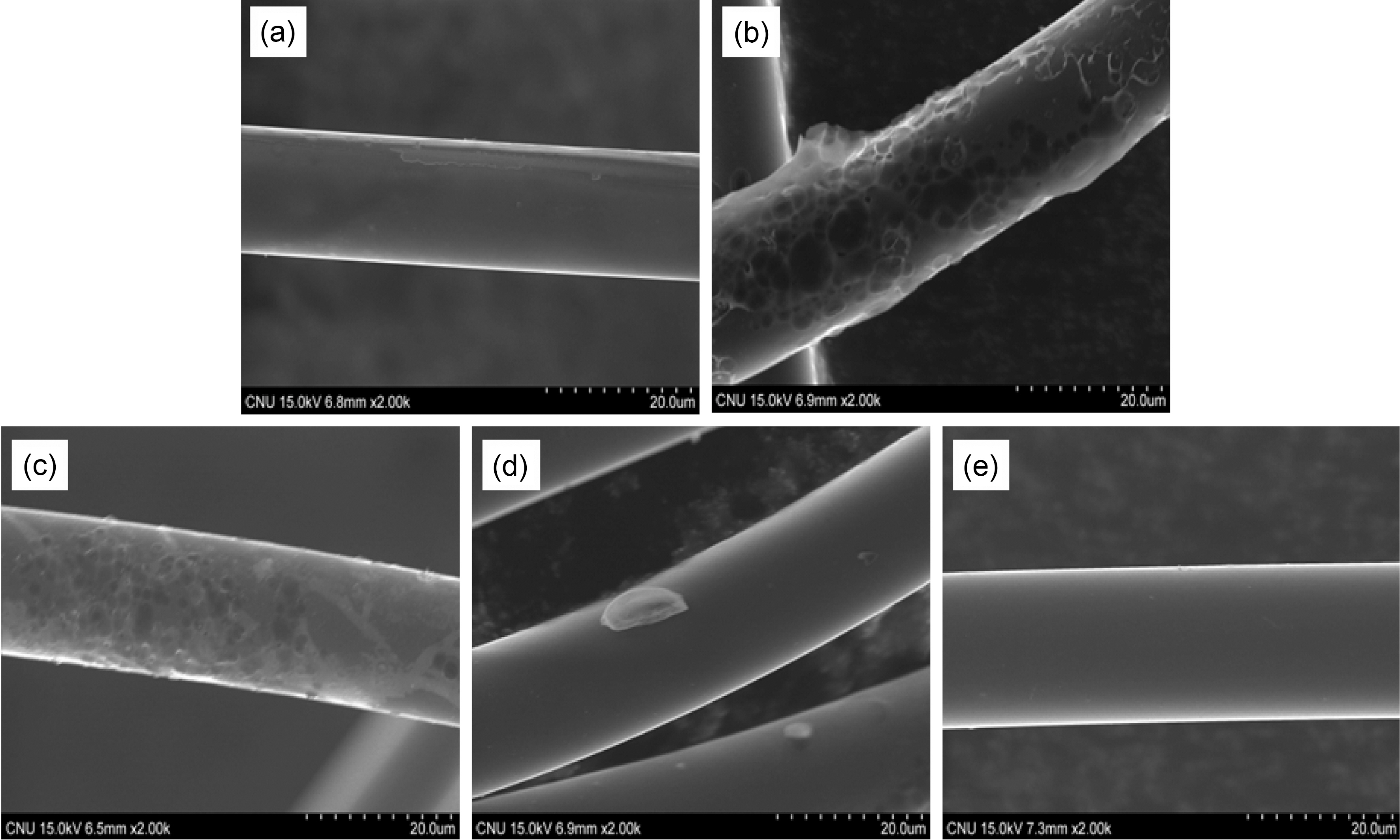
Fig. 1 shows the SEM images of the as-received and ACFs after propellant waste impregnation and heat-treatment. The surface of K500 that heat-treated at 500℃ look smooth like the surface of as-received ACF. But heat-treatment temperature was lower, the surface of ACFs were rougher like as morphology of impregnated ACF before heat-treatment. This means the impregnated propellant waste was imperfectly heat-treated and the residue was exist on surface of ACF if the heat-treatment temperature is lower than 400℃. Compared the SEM images of K-500 before and after modification using propellant waste, the surface of ACF was not destroyed after heat-treatment of propellant. This result was the same appearance as researches that was treated ACF with nitrocellulose [21].
3.2. Thermogravimetric analysis
Fig. 2 shows TGA curves of the as-received and modified
[Fig. 2.] TGA curves of the as-received and modified ACFs with different heat-treatment temperature.
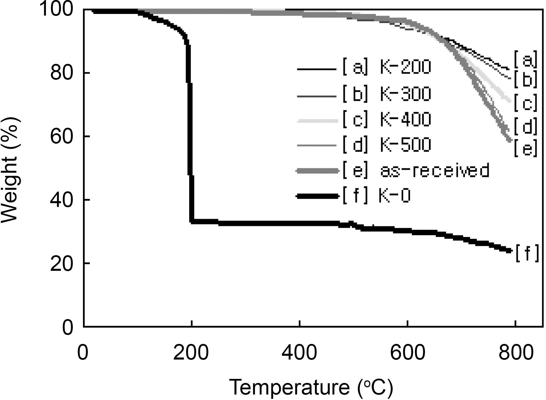
ACFs in nitrogen flow. The weight loss of the K-0 was started from 110℃ and very rapidly progressed at 190℃ remaining 33 wt%. The 190℃ was coincided with the ignition point of propellant waste. And the remaining was the amount of ACF. Therefore, the 67 wt% burn-off is believed as the impregnated amount of propellant waste. The weight losses of the as-received and the ACF which was propellant waste impregnated and heattreated at 500℃ were slowly started above 500℃ showing very stable, because which were already heat-treated at 500℃. They were rapidly degraded after 600℃ showing the decomposition of surface functional groups. On the other hand, the 200, 300, and 400℃ heat-treated ACFs were slowly degraded after 400℃ showing the slow decomposition of functional groups which were formed by propellant waste. It was confirmed that the thermal stability of the modified ACFs was defended on the heat-treatment temperature and the optimum heat-treatment temperature is recommended as 500℃.
3.3. Characterization of pore structure
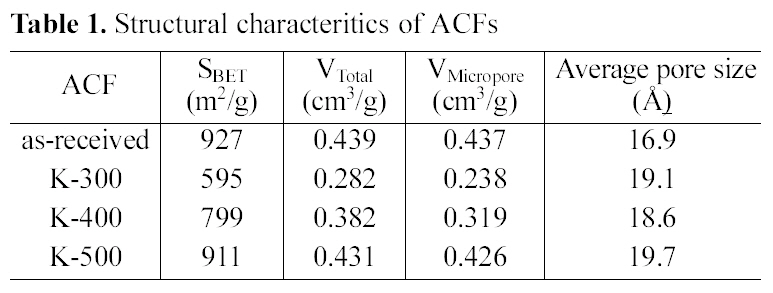
Structural characteristics of ACFs were listed in Table 1. The specific surface area and total pore volume decreased after impregnation and heat-treatment. The specific surface area, total pore volume, and micropore volume of the asreceived ACF were far decreased by propellant waste impregnation and heat treatment at 300℃ due to the propellant coating and unsufficient burn-off. However, those were increased by increasing the temperature to 400℃, and recovered almost same levels to those of as-received when the ACF was heat treated at 500℃. While, the average pore size was rather increased by modification. This indicates that some micropore entrances of ACF were blocked by newly developed functional groups, which was already reported by other researchers [5,22]. This result also suggested that 500℃ is the optimum heat-treatment temperature to modify the propellant waste impregnated ACF in relating to
[Table 1.] Structural characteritics of ACFs

Structural characteritics of ACFs
structural characteristics and thermal stability.
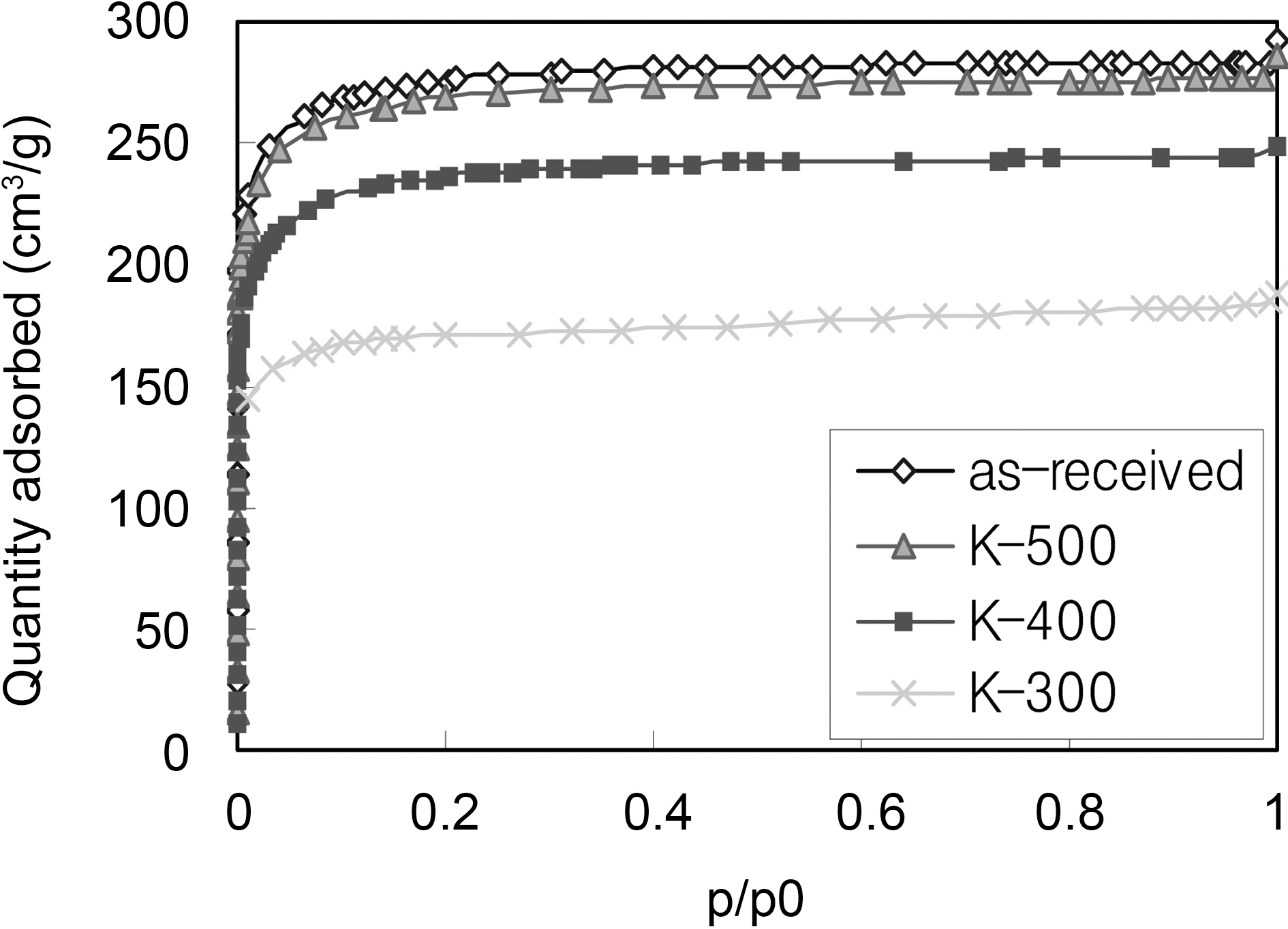
Fig. 3 shows the nitrogen adsorption isotherms of the asreceived and modified ACFs. All isotherms are Type I according to the BDDT (Brunauer- Deming-Deming-Teller) classification, which illuminates the domination of micropores in the porosity.
In consideration of SEM observations and pore structure,the newly developed nitrogen groups might be combined with carbon atoms at the entrance of micropores during heattreatment, however the narrow pore size became wider without reducing the specific surface area, especially at 500℃, and this result was already confirmed by our previous report and other researchers [5,17,22]. On the other hand, some uncombustible propellant residues blocked the pore entrances with heat-treatment temperature below 400℃.
Table 2 shows elemental analysis of ACFs. Compared with the as-received ACF, the carbon contents of the modified ACFs decreased, while the contents of hetero-atoms such as nitrogen or oxygen were significantly increased, especially the nitrogen content increase four times after propellant waste heat-treatment at 500℃. These results indicate that nitrogen and oxygen atoms in propellant waste were transferred to ACF surface through the heat-treatment process. This was also reported in the previous research [17].
[Table 2.] Elemental analysis of the as-received and propellant waste modified ACFs
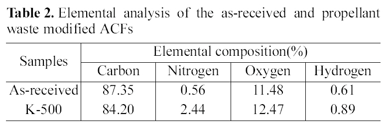
Elemental analysis of the as-received and propellant waste modified ACFs
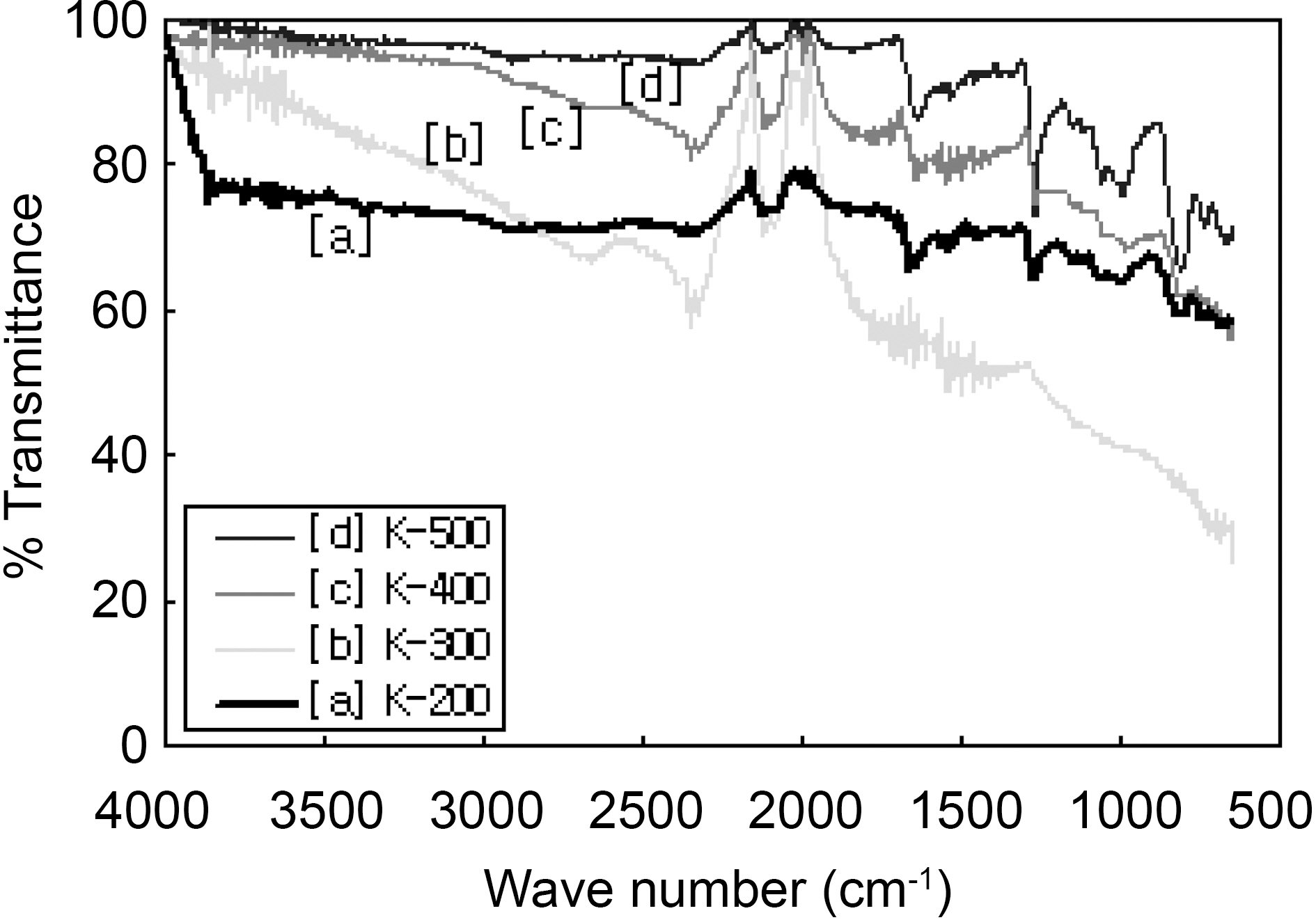
FTIR spectra of modified ACFs were shown in Fig. 4. Spectra show major four peaks at wave number 2345, 2125, 1650, and 1270 cm-1.
The intensity and shape of these peaks was changed with heat-treatment temperature showing the development of different functional groups. The peak range from 1250 cm-1 to 1350 cm-1 might indicates aromatic amines (primary, secondary: 1250~1300 cm-1, tertiary : 1250~1350 cm-1) [23]. The peak intensity of aromatic amine increased as the increase of heattreated temperature. On the other hand, the peak of aliphatic nitriles(2340 cm-1) decreased with the increase of heattreatment temperature. The peak of 2125 cm-1 might be designated aromatic isonitriles (2100 cm-1) and aromatic nitriles (2200 cm-1). This peak decreased as like as aliphatic nitriles. These results implied that aliphatic nitriles were changed to aromatic amines by heat-treatment at high temperature. The peak of 1650 cm-1 that keeps constant might be nitrates (1600~1690 cm-1), carboxyl, ester, lactone(1645 cm-1), and aromatic primary amine (1550~1650 cm-1).
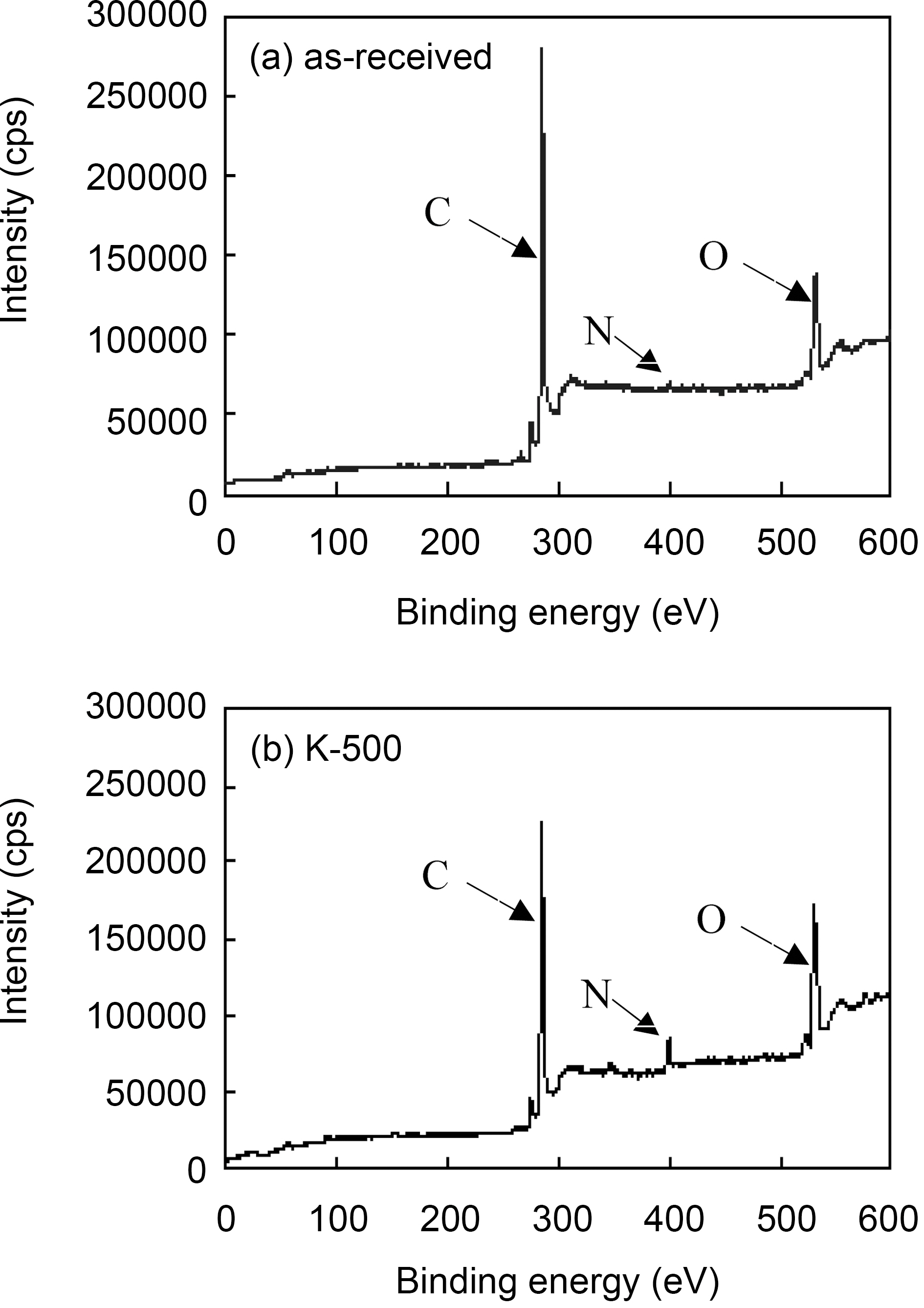
The nature of surface functionalities fixed on the surface of ACFs was studied by XPS, which revealed the composition of the most external surface of the ACFs [18,21,24]. Fig. 5 shows the XPS spectra of the as-received and the modified ACFs. The major peaks in the spectra were due to the C1s
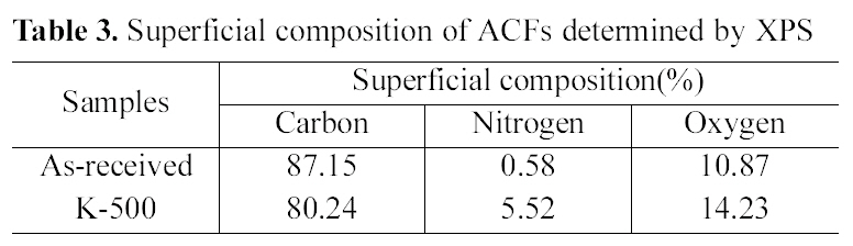
[Table 3.] Superficial composition of ACFs determined by XPS

Superficial composition of ACFs determined by XPS
and O1s photoelectrons. N1s peak of the asreceived ACF around 400 eV was very small, while that of the modified ACF remarkly increased. This means nitrogen groups were introduced on ACF surface by propellant waste impregnation and heat-treatment, and this nitrogen groups might be interacted with the surface carbon to form new surface functional groups, which have resulted in the increase of carbon surface refractoriness[25].
Table 3 shows the superficial composition of ACFs. Atomic ratios were calculated from the XPS spectra after correcting the relative peak areas by sensitivity factors according to the transmission characteristics of the physical electronics SCA[25].
The graphitic carbon content in the as-received ACF hit a peak, while that of nitrogen content shows the lowest value.
When propellant waste was impregnated, nitrogen content increased comparing with the as-received ACF. Oxygen content also increased from 10.87 to 14.23% with heat treatment of 5 wt% propellant waste impregnation. This result indicates that the surface functionalities of ACF were changed through propellant waste heat-treatment. Nitrogen and oxygen containing radicals produced during the propellant heat-treatment were easily combined with the surface carbons, resulted in the increase of the nitrogen and oxygen contents as expected [22].
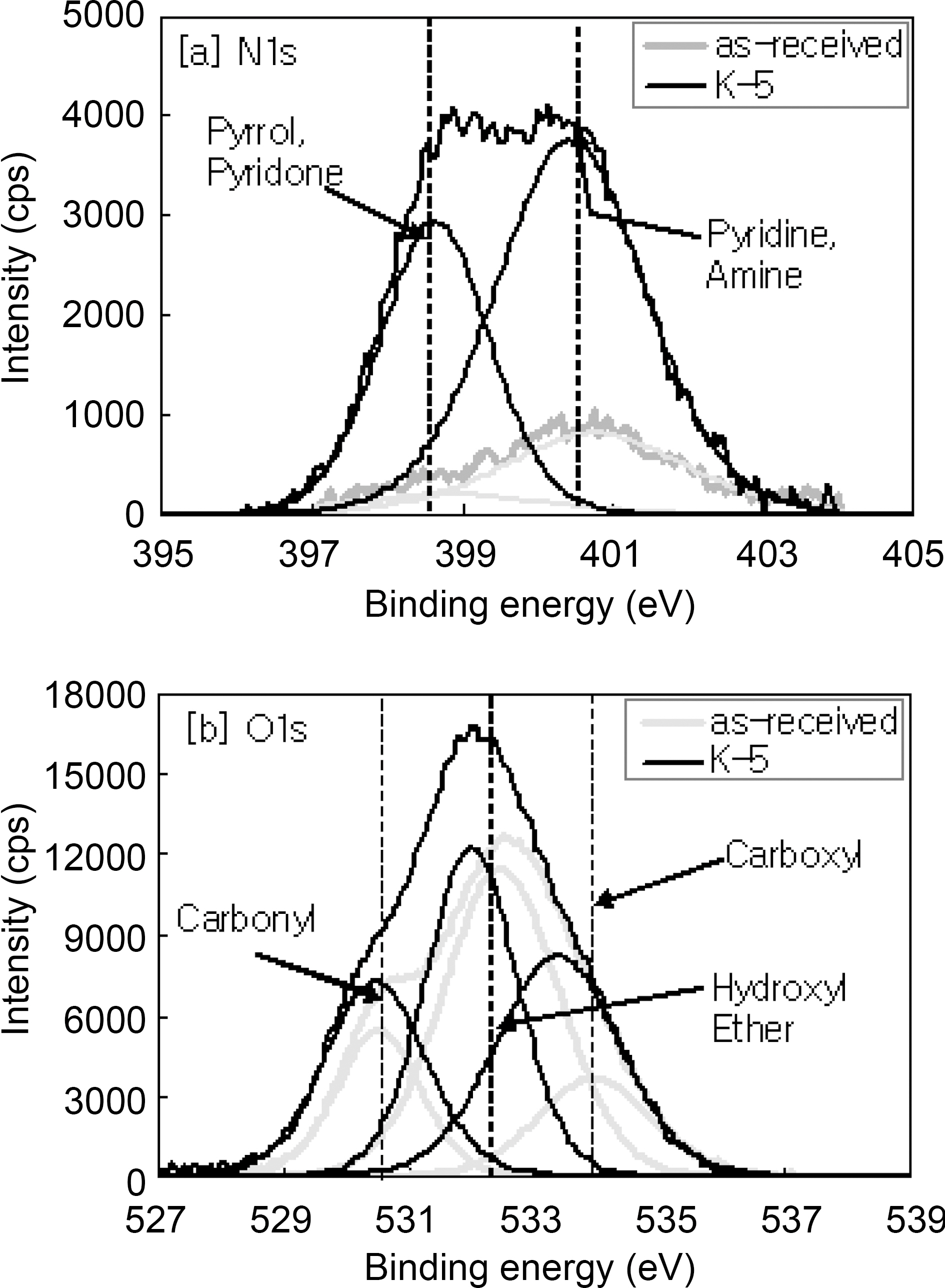
High resolution spectra of N1s and O1s as shown in Fig. 6 was acquired over 395~405 eV and 527~539 eV with a step size of 50 meV in order to confirm nitrogen and oxygen functional groups, respectively. It was convinced that peak intensities of nitrogen increase to 4,085 cps from 930 cps by surface modification. Electron binding energies of nitrogen and oxygen functional groups in carbonaceous materials were designated as Table 4 [18,19,25].
The major peak of the as-received ACF was a sign of pyridone or pyrrole(400.5 ± 0.2 eV). The curve configuration of K-500 consisted of two peaks; one was pyridone like that of the as-received and the other presents pyridine (398.5 ±0.2 eV). It was convinced that there are three peaks corresponding to carbonyl groups (530.4~531.1 eV), hydroxyl
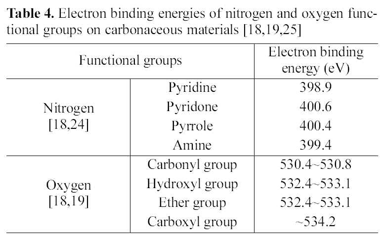
Electron binding energies of nitrogen and oxygen functional groups on carbonaceous materials [18,19,25]
and ether groups (532.3~533.1 eV), and carboxyl groups (534.2 eV). These results suggested that new functional groups were developed on the ACF by propellant waste modifi- cation.
The nitrogen functional groups can be introduced on the surface of activated carbon fiber by simple and controllable impregnation and heat-treatment of propellant waste. The optimum heat-treatment temperature for surface modified ACF was about 500℃. Because low temperature give rise to remarkable decrease of specific surface area and pore volume due to the residue of impregnated propellant waste. The average pore size of ACF can be slightly broaden by blocking the entrance of narrow micropores with newly introduced functional groups. However, there is no morphological damages on the surface of porous carbon by heat-treatment of propellant waste at 500℃.
The newly functional groups were introduced to the surface of ACF by impregnation and heat-treatment of propellant waste. The nitrogen functional groups are pyridine, pyridone and pyrrol and oxygen functional groups are carboxyl, carbonyl and lactone group.


![Highresolution spectra of [a] N1s and [b] O1s on the asreceived and the modified ACF (K-500).](http://oak.go.kr/repository/journal/10466/HGTSB6_2010_v11n2_131_f006.jpg)
![Electron binding energies of nitrogen and oxygen functional groups on carbonaceous materials [18,19,25]](http://oak.go.kr/repository/journal/10466/HGTSB6_2010_v11n2_131_t004.jpg)