In this work, the effect of carbon nanofibers (CNFs) addition on physicochemical characteristics of CNFs-reinforced epoxy matrix nanocomposites was studied. Poly (amide imide) solutions in dimethylformamide were electrospun into webs consisting of 250±50 nm fibers which were used to produce CNFs through stabilization and carbonization processes. As a result, the CNFs with average diameter of 200 ±20 nm were obtained after carbonization process. The nanocomposites with CNFs showed an improvement of thermal stability parameters and fracture toughness factors, compared to those of the specimen without CNFs, which could be probably attributed to the higher specific surface area and larger aspect ratio of CNFs, resulting in improving the mechanical interlocking in the nanocomposites. Also, the applied external loading can effectively transfer to CNFs because strong interactions are resulted between the epoxy matrix and the CNFs.
When the diameters of polymer fiber materials are shrunk from micrometers (e.g. 10~100 ㎛) to submicrons or nanometers (e.g. 10× 10-3-100×10-3 ㎛), there appear several amazing characteristics such as very large surface area to volume ratio (this ratio for a nanofiber can be as large as 103 times of that of a microfiber), flexibility in surface functionalities, and superior mechanical performance (e.g. stiffness and tensile strength) compared with any other known form of the materials [1]. These outstanding properties make the polymer nanofibers to be optimal candidates for many important applications. A number of processing techniques such as drawing [2], template synthesis [3,4] phase separation [5], self-assembly[6,7], electrospinning [8,9], etc. have been used to prepare polymer nanofibers in recent years.
Carbon nanofibers (CNFs) are widely interesting because they have unique combination of mechanical, electrical, and thermal properties. CNFs also possess high flexibility, low mass density, and large aspect ratio. CNFs prepared by vapor grown process, usually present diameters on the order of 20~100 nm and lengths between 10 and 200 ㎛ [10,11]. They tend to have outstanding mechanical properties, with Young modulus in the range 100~1000 GPa and tensile strength between 2 and 4 GPa [12,13]. Another important advantage of CNFs is their lower costs with regard to carbon nanotubes. For all these reasons, CNFs are being investigated as potential candidates of being used for reinforcing polymer matrices to improve their properties
As described above, CNFs can be produced by traditional vapor growth (VG) [14] or plasma enhanced chemical vapor depositing (PECVD) method [15], which was developed at the beginning of this century. However, VG or PECVD involve a complicated process and high cost. Therefore, new methods for CNFs are being developed and CNFs can be produced by electrospun of polymer solutions, and stabilizing and carbonizing process in a fairly cost-effective manner [16].
Epoxy resins are one of the most important thermosetting polymers, which are extensively used as the structural adhesives and coatings, and other plastic engineering materials because of their high modulus and thermal stability properties. Also, epoxy resins are widely used in the electronics industry as molding and sealing compounds for electronic packaging. Especially, these thermosetting resins have a variety of useful properties, including excellent insulating characteristics, good adhesive properties, outstanding chemical resistance, retention of properties under severe operating conditions, low moisture adsorption, and no reaction by-products that could cause void formation or act as plasticizers [17,18].
Recently, CNFs were produced by pyrolyzing electrospun nanofibers from PAN, PAI, etc and from pitch with typical diameters of few hundreds of nanometer and several microns, respectively. However, the structure and the mechanical properties of CNFs and their reinforced polymer matrix nanocomposites are largely unknown. The purpose of this paper is to characterize the structure and to explore the mechanical properties of electropsun PAI-derived CNFsbased epoxy matrix nanocomposites.
2.1. Materials and sample preparation
Epoxy resins (EP) used in this study was diglycidylether of bisphenol-A (DGEBA, YD-128 supplied from Kukdo Chem. Co. of Korea). Epoxide equivalent weight of the DGEBA was 185~190 g/eq. and the density was 1.16 g/cm3 at 25℃. 25 wt.% poly (amide imide) (PAI) dissolved in dimethylformamide in a solvent was gently stirred for 5 h at about 180℃, and evolution of the solvent during dissolution was avoided by refluxing the solvent. All reagents were used without further purification.
The solution was spun in a fiber web using an electrospinning apparatus equipped with a power supply (10~25 kV DC, Convertech Co. of Korea). The glass pipette used in these experiments had a capillary tip diameter of 0.42 mm, and the pipette was tilted at approximately 5° from horizontal such that a small drop was maintained at the capillary tip due to the surface tension of the solution. A positive potential was applied to the PAI solution, by inserting a copper wire into the glass pipette or by directly attaching the lead to a high voltage power supply outside of the hypodermic needle. The collection screen was a 10×10 cm copper plate, which serves as a grounded counter electrode, placed horizontally at a location 25 cm from the tip of the pipette. The applied voltage ranged from 10 to 20 kV and the distance from the tip to collector was 10 cm. The prepared electrospun webs consisting of approximately 220±60 nm nanofibers were finally thermally annealed under a N2 condition to produce nanofibers through a stabilization process.
All the experiments were performed at room temperature in air. The as-spun PAI fibers were collected on aluminum oxide (alumina) substrates that were attached on the edge of the collecting wheel. For carbonization, the substrates were placed in a tube furnace and stabilized in air for 30 min at 250℃, then carbonized for 1 h in nitrogen at 800℃, and finally heated at 1100℃ in nitrogen for another hour; the ramp rate was 2℃/min between the 800 and 1100℃ plateaus.
2.2. Functionalization of CNFs
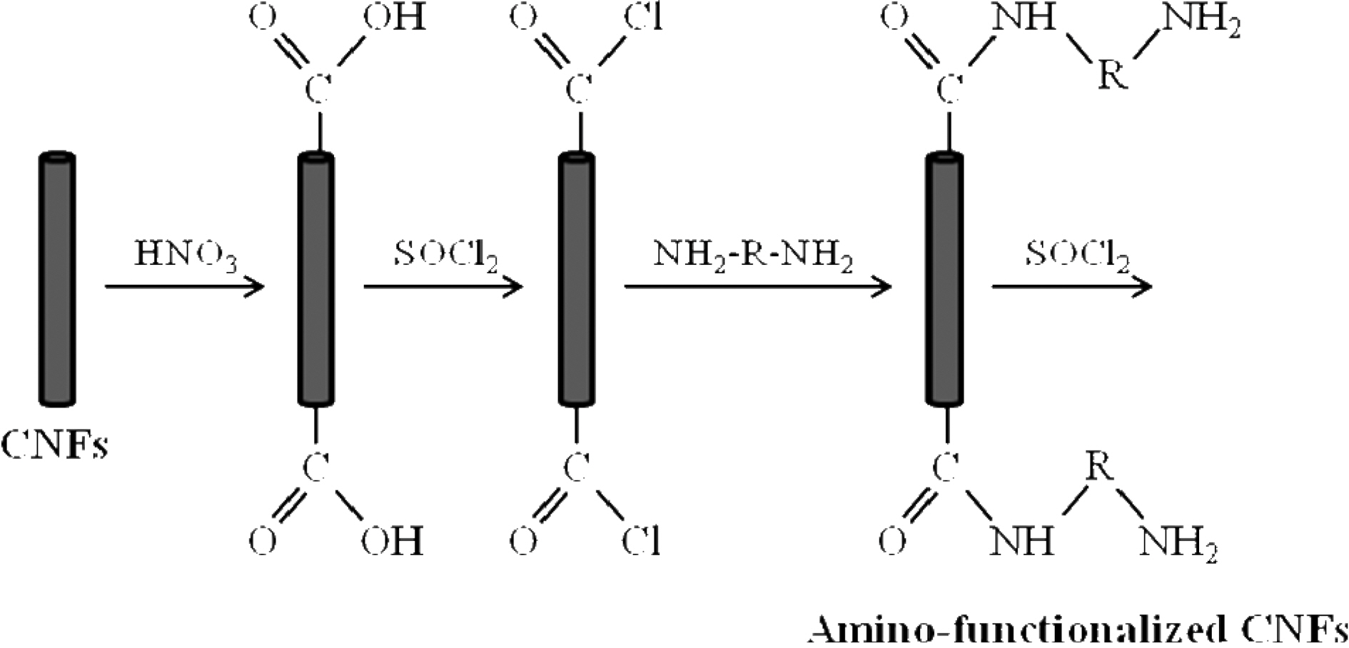
The applied functionalization process consisted of three stages treatment: oxidation, acylation and amino
unctionalization with DDM. To oxidize the CNFs, they were treated with concentrated nitric acid at 70℃ for 4 h. After washing with distilled water until the filtrate reached a pH value of 7, the nanofibers were dried in vacuum at 60℃. The surface oxidized-CNFs were acylated by chemical reaction with thionyl chloride at 70℃ for 24 h. Then the mixture was cooled, washed with tetrahydrofurane (THF) and vacuum filtered. Finally, surface acylated-CNFs were reacted with DDM at 60℃ in ethanolic solution for 96 h. After vacuum filtration and washing with THF, the DDM-derivatized CNFs were dried at reduced pressure overnight. The different stages of the CNF surface modification are schematized in Fig. 1.
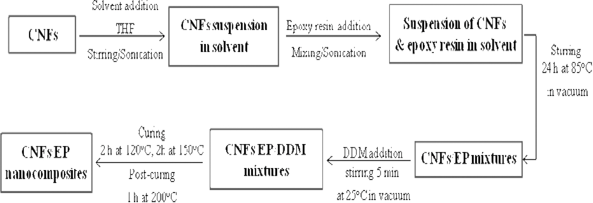
The epoxy resins were mixed with 5 wt.% of purified and amino-functionalized CNFs using a solvent to decrease the epoxy viscosity and, in principle, to enhance the nanoreinforcement dispersion in the CNFs/EP nanocomposites. Then the curing agent was added to the CNFs/EP and stirred thoroughly. The mixtures were degassed to remove bubbles before casting into a mold. The samples were cured for 2 h at 120℃, 2 h at 150℃ and 1 h at 200℃. Hereafter, we designated the specimen as follows: pure epoxy resins and PAI-based CNFs/epoxy resins were EP and CNFs/EP nanocomposites, respectively. Scheme of the processing stages of CNFs/EP nanocomposites was displayed in Fig. 2.
The diameter and morphology prepared of CNFs/EP
nanocomposites were examined with scanning electron microscope (SEM, JEOL Model 840A). A small section of the non-woven mat was placed on the SEM sample holder and sputter-coated with gold (Denton Desk-1 Sputter Coater). An Amray 3000 SEM using an accelerating voltage of 20 kV was employed to take the SEM photographs.
Thermogravimetric analysis as performed with a Du Pont TGA-2950 analyzer to investigate the thermal stabilities of CNFs/EP nanocomposites from 30 to 850℃ at a heating rate of 10℃/min in the nitrogen atmosphere.
The fracture toughness parameter, critical stress intensity factor (KIC) and specific fracture energies (GIC) of CNFs/EP nanocomposites were characterized by single-edge-notched(SEN) tested in a three-point flexural test, which was conducted on a united test machine (Instron Model 1125 mechanical tester), according to the ASTM E-399. All mechanical property values were obtained by averaging the five experimental values.
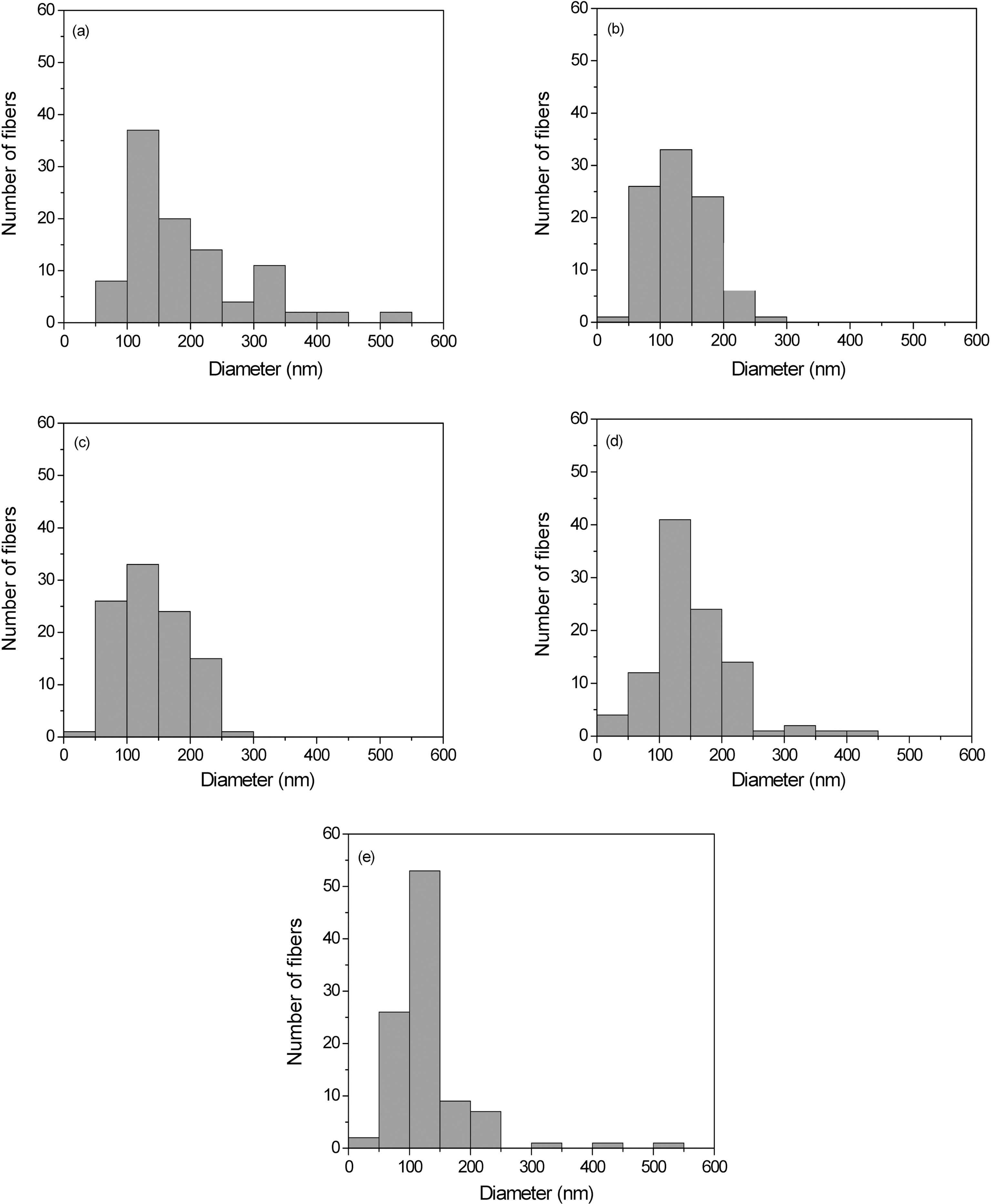
Fig. 3 indicates the distribution of diameter for the PAIderived nanofibers. The fiber distribution is becoming
gradually narrower with increasing the voltage. The average fiber diameter decreases from 300 to 150 nm for 10~20 kV voltages applied. Although a systematic study to determine the optimal electrical field and concentration for these nanofibers with regard to fiber diameter is not completed, it appears that the deposited thickness of the nanofibers is relatively independent of the current voltage of the power supply under these conditions.
The fiber diameter and morphology indicate that the fibers produced are not nanofibers; however, these results are essentially identical to those obtained by Reneker and others [19,20] who have extensively studied the electrospinning of nanofibers from both chloroform and aqueous solutions. They note that although PAI-based nanofibers electrospun from chloroform have larger fiber diameters (1~2 ㎛) with a uniform thickness, this solvent eliminate the “beads on a string” morphology [21] sometimes found in thinner PAIbased nanofibers (200~300 nm) electrospun from aqueous solutions.
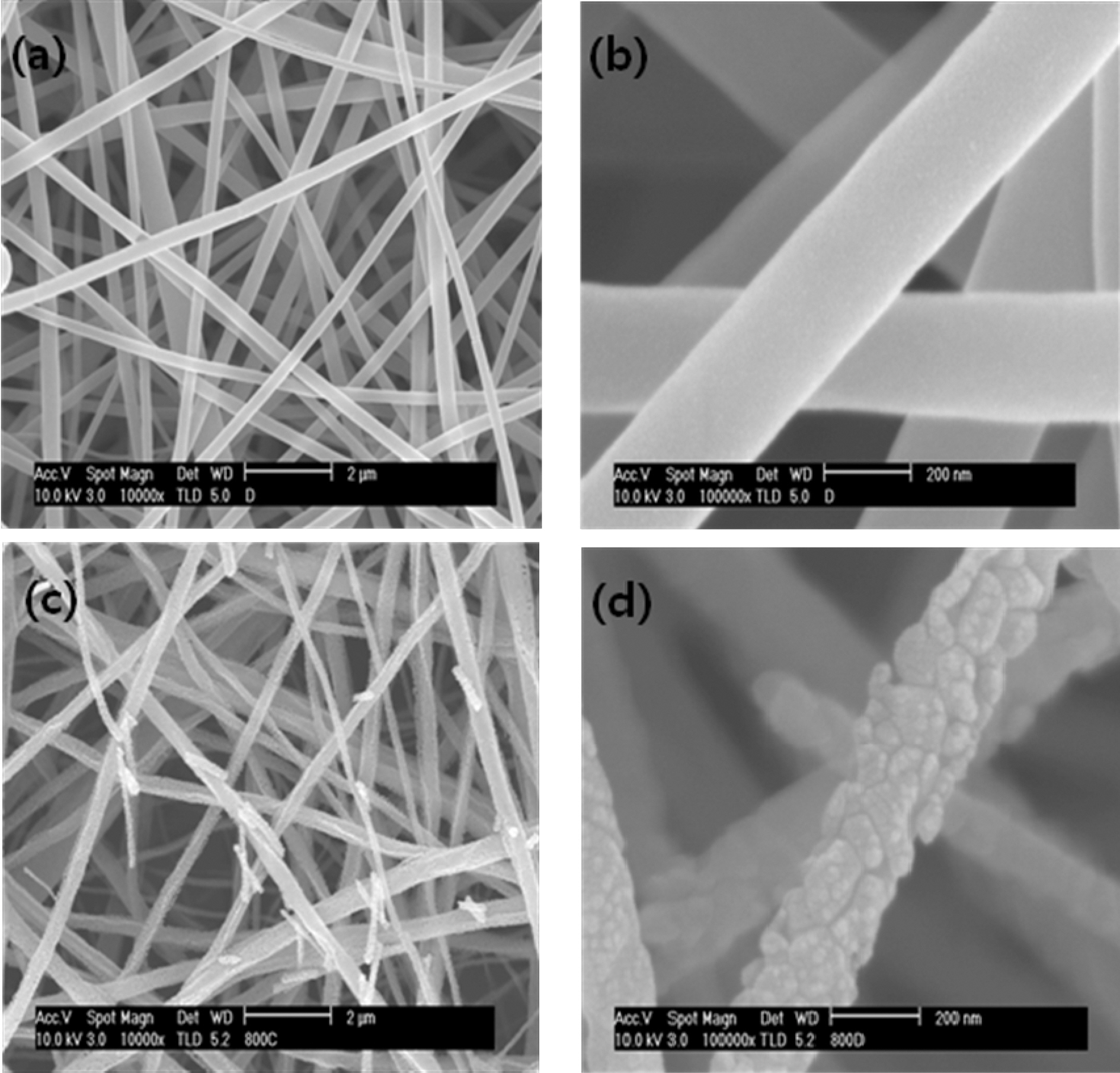
Fig. 4 shows SEM images of electrospun nanofibers and CNFs at different magnifications. After a collection time of 1 h electrospun polymer fibers form a dense mat with a porosity of ~30% and a thickness of 50 ㎛, as shown in Fig.4 (a) and (b). Individual fibers have a uniform cross-section with an average diameter of 250± 50 nm, although in some cases beads appear; these are due to capillary instability. In certain instances, a connection between the collected fibers is observed which probably formed during the process of fiber deposition. After the carbonization process (Fig. 4 (c)and (d)), the mat retained its shape and the average diameter shrank to 200 ± 20 nm.
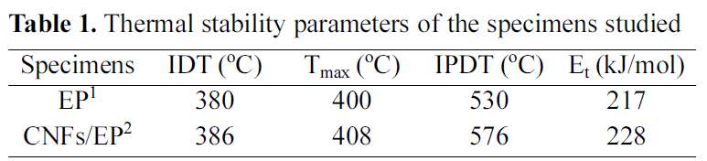
The thermal degradation behavior of CNFs/EP nano-
[Table 1.] Thermal stability parameters of the specimens studied

Thermal stability parameters of the specimens studied
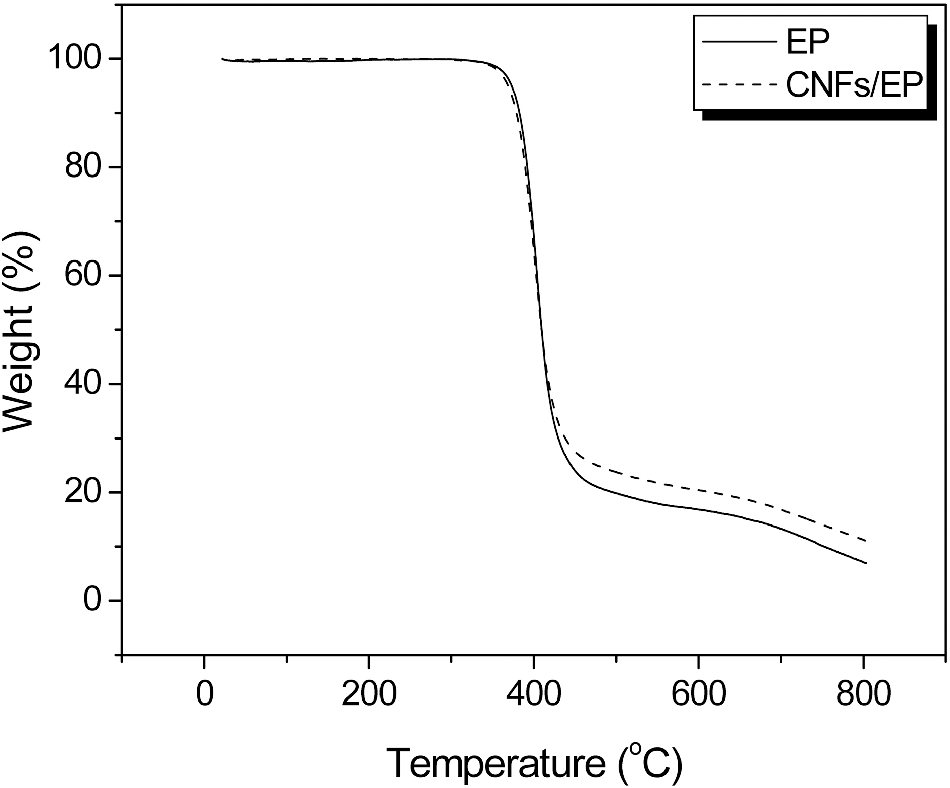
nanocomposites is studied with TGA at a heating rate of 10℃/min in the nitrogen atmosphere. The TGA thermograms of CNFs/EP nanocomposites cured by DDM are shown in Fig. 5. The weight loss is shifted to higher temperature with addition of CNFs into the epoxy resins.
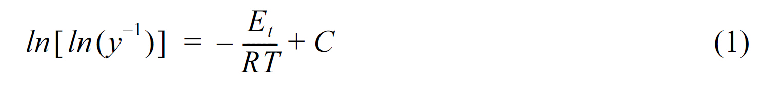
Thermal stability parameters, including the initial decomposed temperature (IDT), temperatures of maximum rate of degradation (Tmax), the integral procedural decomposition temperature (IPDT), and decomposition activation energy (Et) of CNFs/EP nanocomposites can be determined from TGA thermograms [22-24] The Et of CNFs/EP nanocomposites is calculated by the integral method of Broido’s equation, as follows: [25]

where Et is the decomposition activation energy, W the weight of the sample at any given time, W0 the initial weights, W∞ the final weights, T the absolute temperature, and R the gas constant.
The results of the IDT, Tmax, IPDT of CNFs/EP nano-composites are listed in Table 1 and the Et values of the systems calculated from the ln[ln(y-1)] versus 1/T are also listed in Table 1. As a result, the thermal stability parameters of CNFs/EP nanocomposites are higher than that of the EP
specimen. This may be caused by addition of the carbon nanofibers in epoxy resins and has altered the state of dangling point in cured epoxy resins, which blocks the easy breakage by pyrolytic, resulting in increasing the thermal stability of cured CNFs/EP nanocomposites, as already noted in the Tg results [26].
The specific fracture energy (GIC) is an important fracture toughness parameter, which describes the state of stress in the vicinity of the tip of a crack at fracture as a function of the specimen geometry, the crack geometry, and the applied load on the basis of linear elastic fracture mechanics [27]. The fracture behaviors of the materials depend on the stress level, flaw concentration, material properties, and failure mechanism. GIC is measured to investigate the effect of fracture toughness on brittle materials with pre-cracks [28].
Based on the Griffith-Irwin equation [28], the resistance to crack propagation, GIC, is increased as the fracture toughness and the Poisson ratio increases or as the electric modulus decreases, as follows [29]:
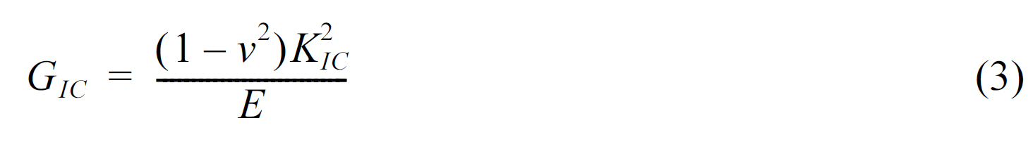
where E is the Young's modulus and v the Poisson ratio (0.3) of the nanofibers.
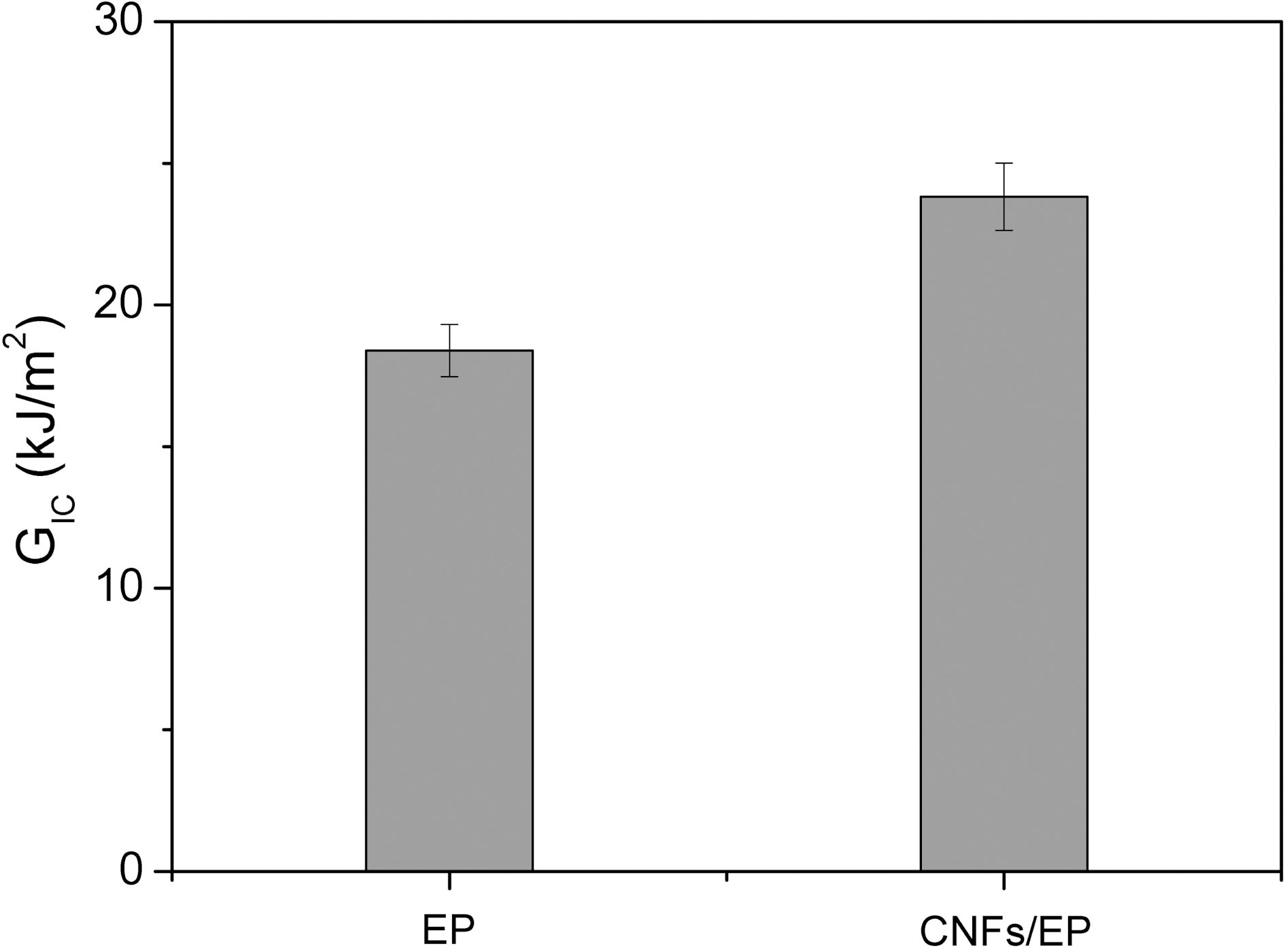
Fig. 6 shows the result of GIC for CNFs/EP nanocomposites. The result clearly indicates that the value in specimen of CNFs/EP nanocomposites is higher than that of the specimen without CNFs. This result can be explained by the reduction of mobility of the epoxy chains that is being increased due to the addition of CNFs having enormous specific surface area to the epoxy resins and newly formation of mechanical interlocking with epoxy matrix, resulting in an improvement in the toughness of CNFs/EP nanocomposites [30-34]. Consequently, the maximum value of both the KIC and GIC is obtained by addition of CNFs. Therefore, we suggest that the additional energy needed to extend the interfacial crack at this condition may be attributed to increased interfacial adhesion between the CNF reinforcement and the epoxy matrix resins in the nanocomposites.
In this work, electrospinning was carried out using 25 wt% PAI solution under fixed tip-to-collect distance (10 cm) and voltage (10~20 kV) in order to fabricate CNFs/EP nanocomposites. As a result, the fiber diameter was decreased with increasing the applied voltage, while the jet instability was increased at high voltage. Stabilized fiber bond structure was formed at 15 kV voltages. And the CNFs/EP nanocomposites showed an improvement of thermal stability parameters and fracture toughness factors, compared to the specimens without CNFs. These results were explained that the CNFs had higher specific surface area and larger aspect ratio, which played an important role in improving the thermal and mechanical interfacial properties of the nanocomposites studied.