In this study, porous electrospun carbon fibers were prepared by electrospinning with PAN and MgCl2, as a MgO precursor. MgO was selected as a substrate because of its chemical and thermal stability, no reaction with carbon, and ease of removal after carbonization by dissolving out in acidic solutions. MgCl2 was mixed with polyacrylonitrile (PAN) solution as a precursor of MgO with various weight ratios of MgCl2/PAN. The average diameter of porous electrospun carbon fibers increased from 1.3 to 3 ㎛, as the MgCl2 to PAN weight ratio increased. During the stabilization step, MgCl2 was hydrolyzed to MgOHCl by heat treatment. At elevated temperature of 823 K for carbonization step, MgOHCl was decomposed to MgO. Specific surface area and pore structure of prepared electrospun carbon fibers were decided by weight ratio of MgCl2/PAN. The amount of hydrogen storage increased with increase of specific surface area and micropore volume of prepared electrospun carbon fibers.
Diversity of porous carbon materials produced so far is remarkable, due to their variety of applications, such as adsorbents, catalytic supports, and etc. [1] and activated carbons are one of the important materials for porous carbon materials. Activated carbons can be produced from various carbonaceous materials. Polymer precursors are especially preferred when carbon with low inorganic impurities is needed. The most well studied polymer is PAN (polyacrylonitrile). PAN-based activated carbons have drawn increasing attention because of their excellent surface properties and adsorption capacity [2].
Porous carbon fibers with smaller fiber diameter have advantages, such as narrower pore size distribution and better adsorption capacity at low concentration of adsorbates compared than conventional activated carbons [3]. The preparation of porous carbon materials needs one more step activation of carbon materials with KOH [4,5], NaOH [6,7] or oxidizing gas [8]. However, there have been reported various precursors and processes to prepare porous carbons without any activation process. Porous carbons were prepared by using various templates, such as zeolites and silicas [9-11]. The template had to be dissolved out by strong acids after carbonization, so its mass production was not easy. A simple process was developed to prepare porous carbon materials from PVA (polyvinyl alcohol) or PVC (polyvinyl chloride) using MgO as the substrate [12,13]. MgO was selected as a substrate because of its chemical and thermal stability, no structural and compositional changes, no reaction with carbon, and convenience of dissolving out in acidic solutions [14]. In this experiment, MgCl2 was newly used to prepare porous carbon fibers as a MgO precursor, because using MgCl2 as a MgO precursor was easier to control pore size distribution than using MgO directly [14]. This suggested a new preparation process of porous carbons without activation processes.
Therefore, in this study, porous electrospun carbon fibers were prepared to apply as a hydrogen carrier by electrospinning with a PAN and MgCl2 solution. The capacity of hydrogen storage was compared by using these electrospun fibers based on the investigation of their pore structure and shape.
2.1. Materials and Sample Preparation
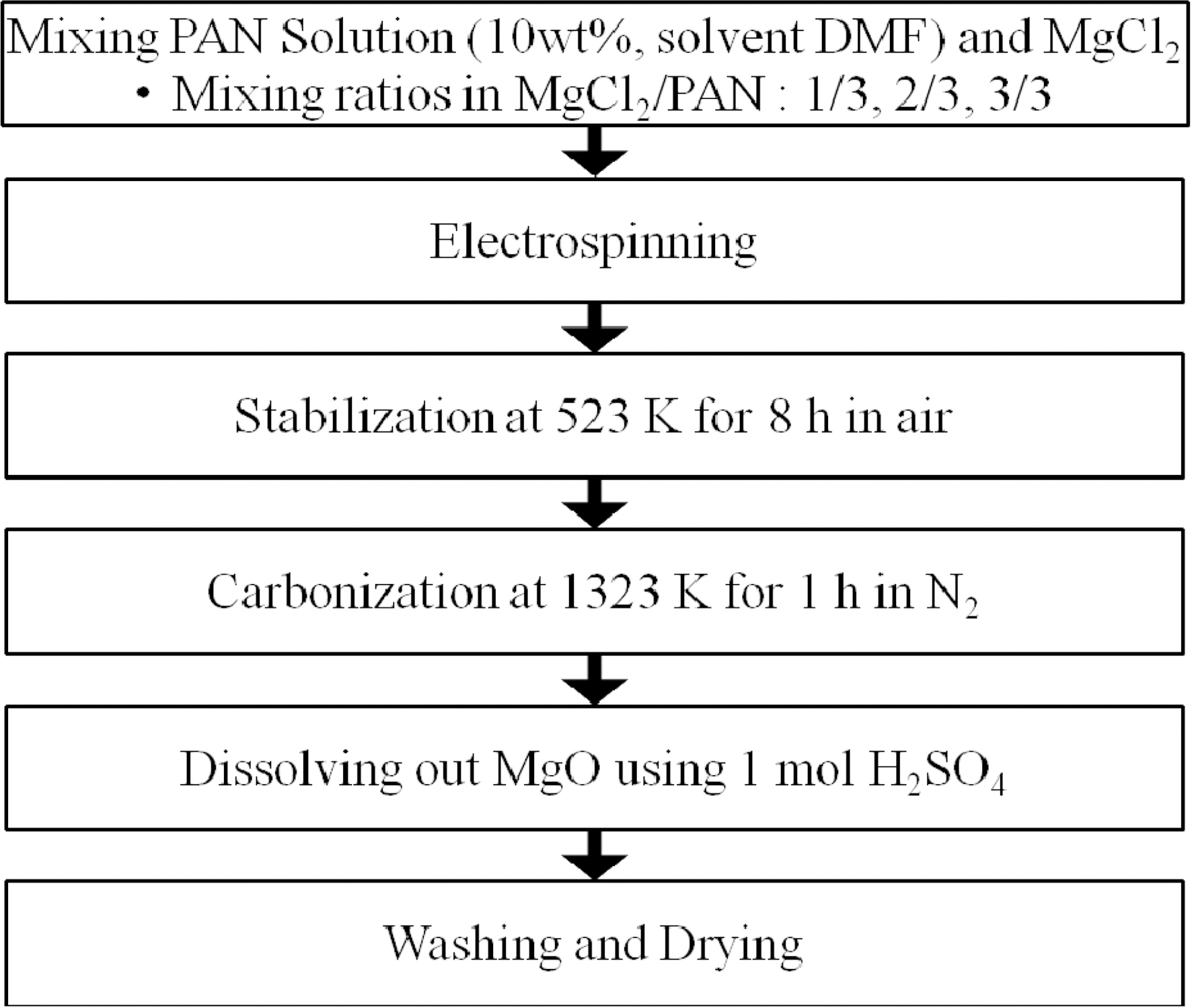
As a MgO precursors, MgCl2 (magnesium chloride anhydrous,Junsei, assay: 97.0%) was used and PAN (polyacrylonitrile, Aldrich) was used as a carbon precursor. PAN was dissolved in DMF (N,N-dimethyl formamide, Acros) at 353 K, with 10 wt% concentration. MgCl2 was added to the PAN solution with various mixing ratios of MgCl2/PAN; 1/3, 2/3, and 3/3, respectively. And the mixed solution was used for electrospinning (voltage: 17 kV, syringe rate: 1.5 cc/h). Then, electrospun fibers were stabilized at a temperature of 523 K for 8 hr in air. Stabilized fibers were
heated at 1323 K for 1 hr under nitrogen atmosphere for carbonization. After carbonization, the substrate MgO was dissolved out of electrospun fibers with 1mol/L H2SO4. The schematic diagram of this procedure is illustrated in Fig. 1. The final electrospun fiber products were called EM1, EM2, and EM3, based on the mixing ratios of MgCl2/PAN.
The morphologies of samples were observed with Scanning Electron Microscope (SEM, JSM-6300, JEOL LTD, Japan). The Samples were subjected to X-ray diffraction (XRD, Model D/MAX-2200 Ultima/PC, CuKα Rigaku, Japan) and thermo gravimetric analysis (TGA, Mettler?Toledo, TGA/SDTA851, Switzerland) in N2 from room temperature to 1073 K, with heating rate of 10 K/min. And Pore structure of carbons was assessed by N2 adsorption with weight ratio of MgCl2. To test hydrogen adsorption capacities, samples were degassed at 473 K for 2 hr and hydrogen adsorption was conducted at 303 K from 0 to 50 atm by using volumetric method with PCT apparatus (Mirae SI Co., Korea).
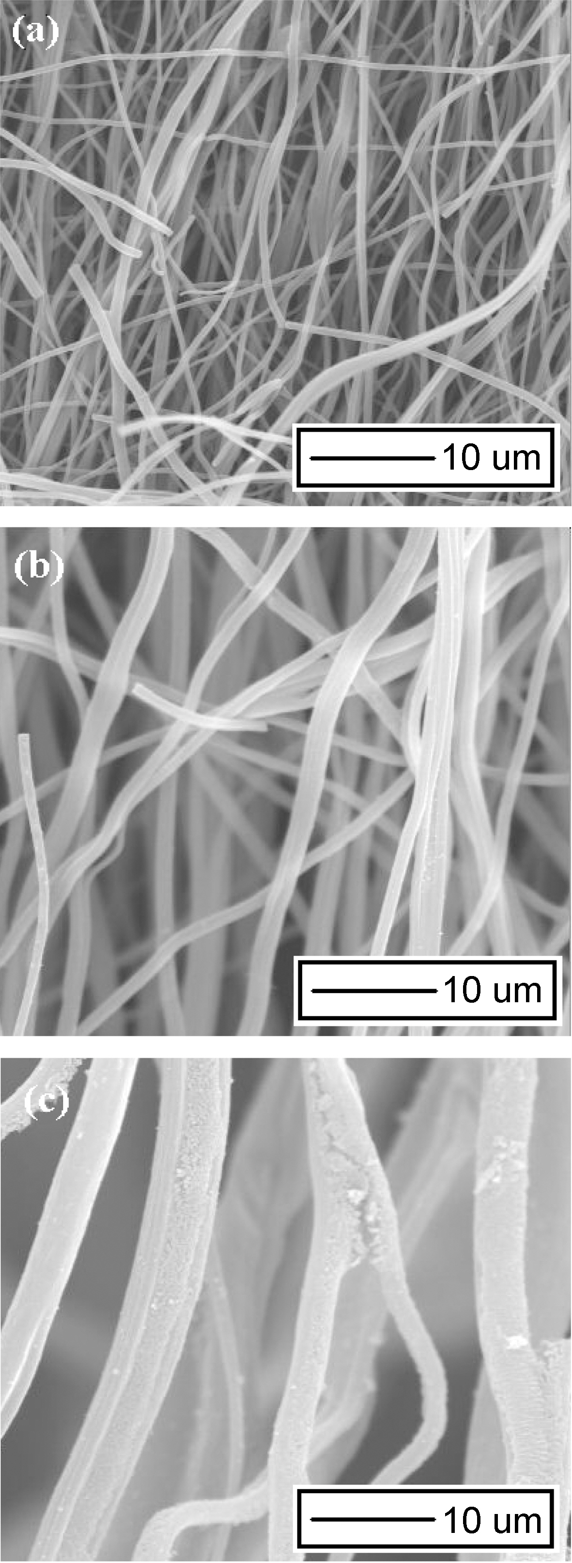
Fig. 2 shows the morphologies of porous electrospun carbon fibers prepared in this study. Average diameter of porous electrospun carbon fibers increases from 1.3 to 3 ㎛ with increasing the amount of MgCl2 added in polymer solution. It is believed that surface tensions, viscosities, and conductivities of polymer solution are changed with the polymer solution composition change [3], and those changes of polymer solution also increase or decrease average diameter of electrospun fibers.
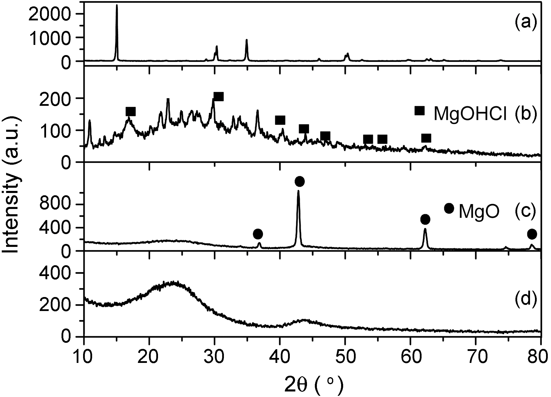
Fig. 3 presents the XRD spectra of MgCl2 in electrospun carbon fibers at each preparation step. Other work by the
authors [15-17] describes the procedure to produce MgOHCl from chemical grade MgCl2. This is in good agreement with our results as shown in Fig. 3. During the stabilization step (Fig. 3 (b)), hydrolysis of MgCl2 is enacted by heat treatment around 458~513 K. Cl produced HCl and then removed from electrospun fiber as a gas state [15].

At the elevated temperature for carbonization step,remained MgOHCl in electrospun fiber is decomposed to MgO and HCl [16].

The decomposition temperature of MgOHCl is calculated to be 828 K [17]. As we can see (c) in this Fig. 3, the MgOHCl mostly decomposed to MgO. The characteristic peaks of MgOHCl at Bragg angles (2 theta) of roughly 15, 32, and 55 degrees diminished after carbonization and eventually completely
disappeared when it was dissolved out by using H2SO4 .
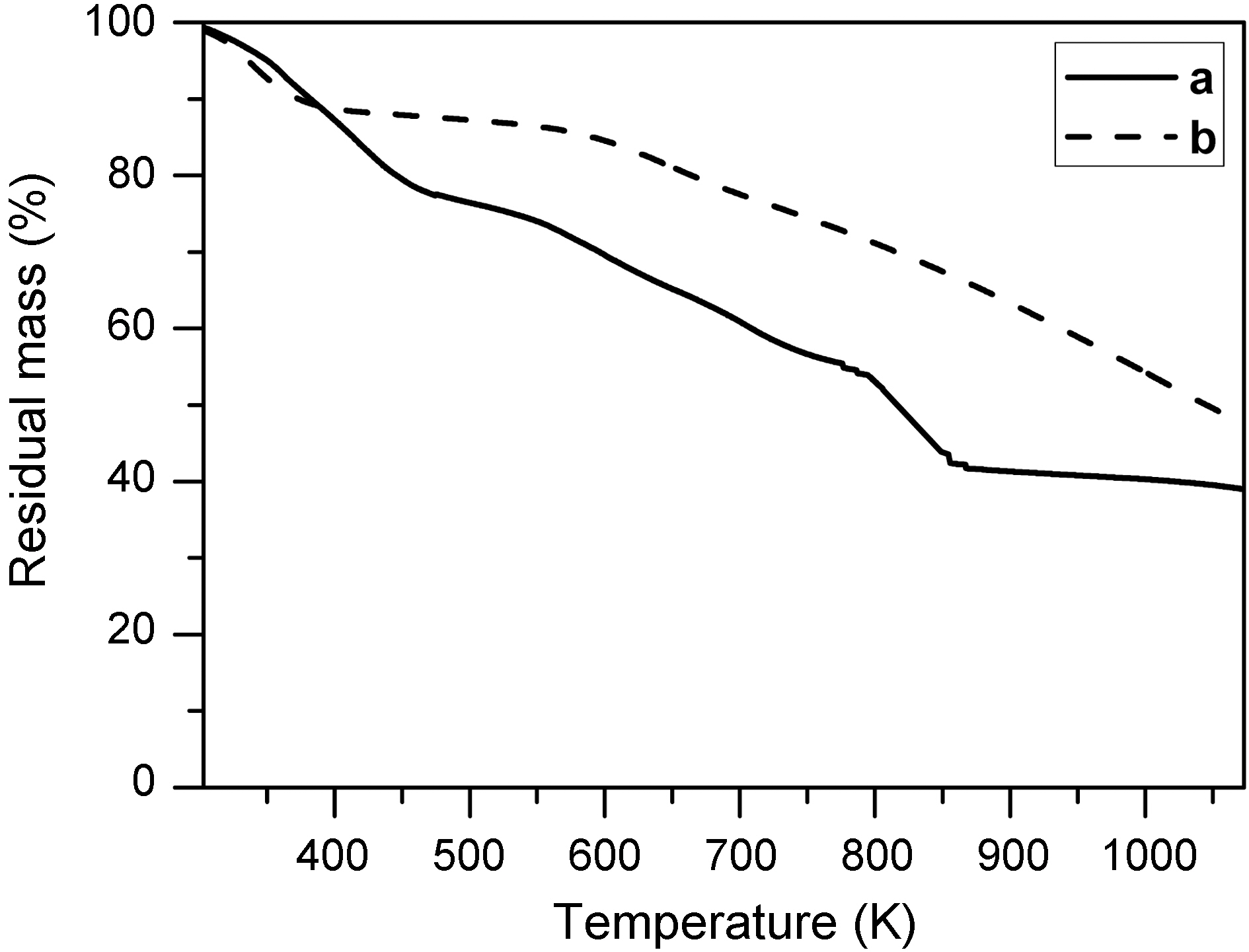
Thermal gravimetric analysis (TGA) was used to study the decomposition of MgOHCl. Fig. 4 is thermogravimetric curves of stabilized electrospun fiber prepared from MgCl2/PAN (2/3) solution ((a); EM2) and stabilized electrospun PAN fiber ((b); without MgCl2). Serious weight loss of the samples EM2 is observed at around 823 K in TGA results, even though the weight of stabilized electrospun PAN fiber (b) decreased linearly with the temperature. This weight loss caused by decomposition of MgOHCl, which occurred around this temperature due to the change from MgOHCl to MgO. This is also supported by XRD results shown in Fig. 3 as mentioned earlier.
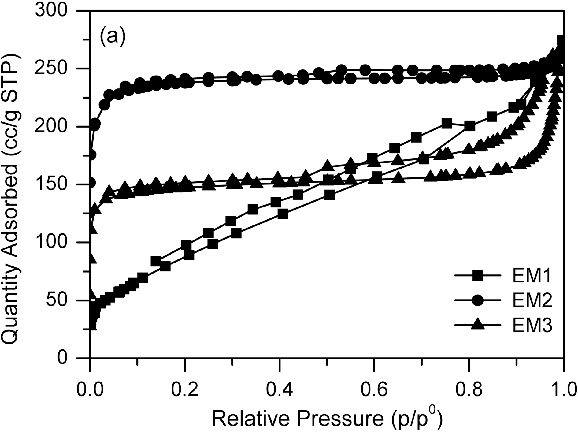
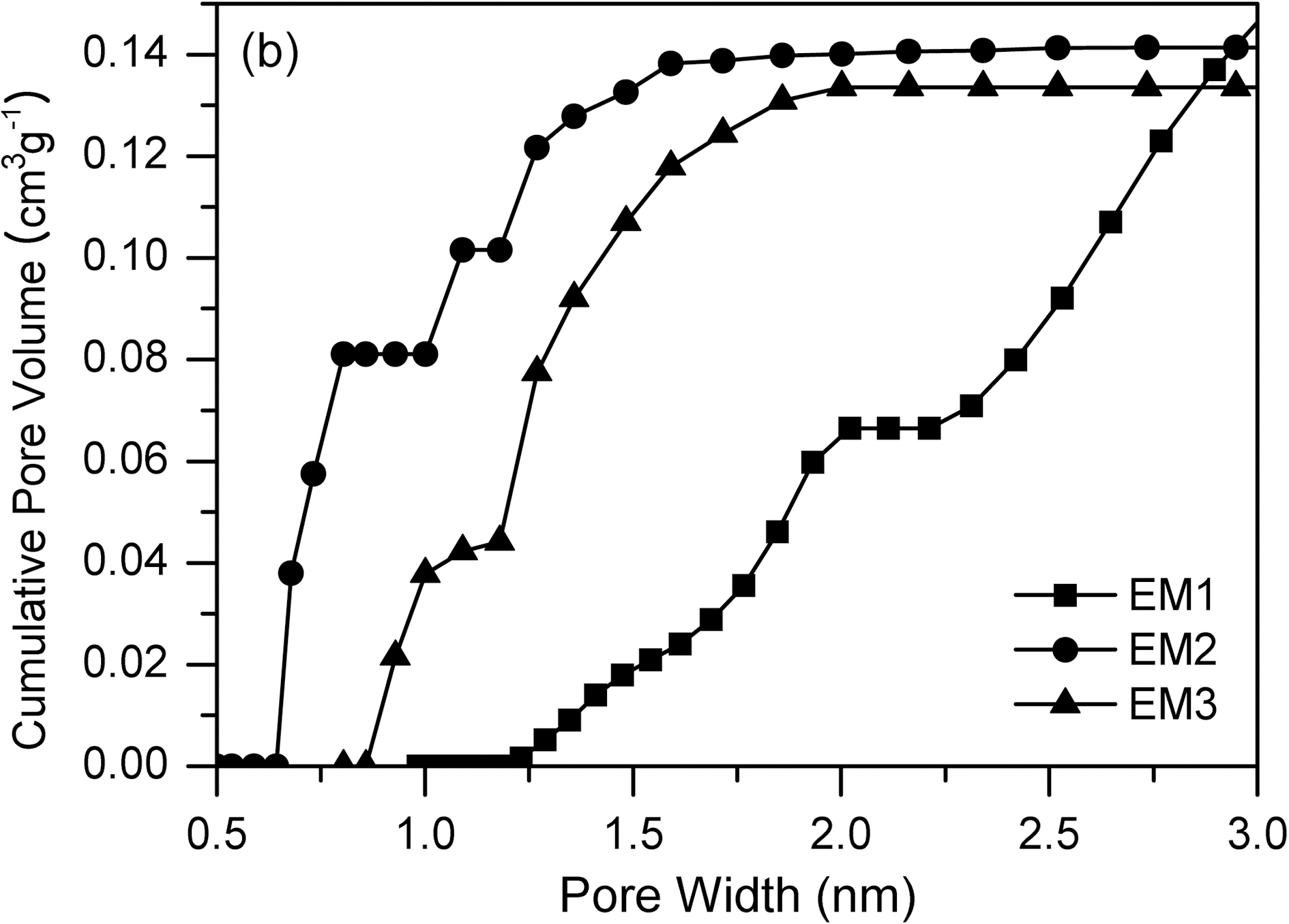
Fig. 5, 6 and Table 1 show the textual properties of porous electrospun carbon fiber prepared. MgO in electrospun carbon fiber was dissolved out completely by using H2SO4 (1 mol/L) and ended up pores in the carbon fiber. The surface area of electrospun fiber increased dramatically, as
the weight ratio of MgCl2/PAN increased. It is believed that weight ratio of MgCl2/PAN determines specific surface area and pore structure. According to the adsorption isotherm by IUPAC classification [18], the sample EM1 is showing Type II, whereas the other samples are showing Type I. It is shown that carbon fiber has almost mesopores, when weight ratio of MgCl2/PAN is 1/3. Whereas on the other weight ratios of MgCl2/PAN is 2/3 and 3/3, dissolving out MgO decomposed from MgCl2 mainly create micropore on electrospun carbon fiber surface. Both EM2 and EM3 samples have the steep change of isotherm curves in low relative pressure (less than 0.01 bar), showing they have the developed micropore structure [19]. They also have the slow change of isotherm curves over 0.1 of relative pressure, indicating the mesopore also was developed through dissolving MgO.
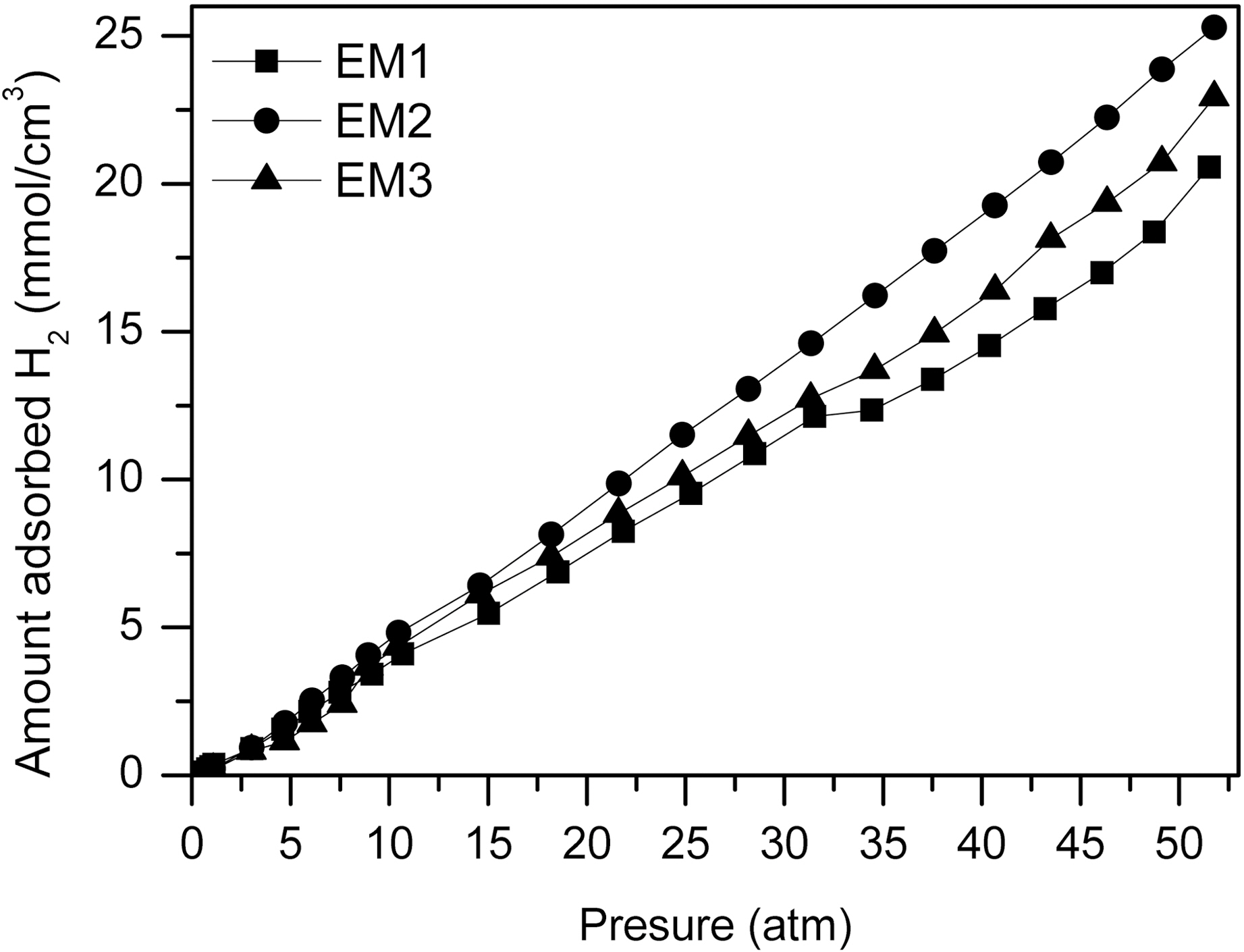
Fig. 7 shows the hydrogen adsorption capacity with changes of the weight ratio of MgCl2/PAN. It is observed that hydrogen adsorption capacity is a linear function of pressure. As the specific surface area and micropore volume increase,
[Table 1.] Pore Parameters Determined by BET and t-plot on the Electrospun Carbon Fibe
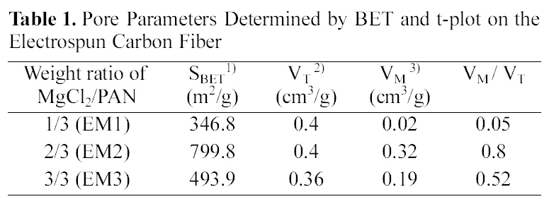
Pore Parameters Determined by BET and t-plot on the Electrospun Carbon Fibe
the hydrogen adsorption of the materials also increases. This result indicates that hydrogen adsorption capacity is positively related to the pore volume in the range of micropore [3,20]. Eventually, the use of electrospinning method from PAN and MgCl2 as the precursor of MgO can be surely one of the way to apply for the hydrogen storage.
Porous electrospun carbon fibers were prepared by using PAN/MgCl2 mixture solution with various weight ratios. Average diameter of porous electrospun carbon fibers increased from 1.3 to 3 ㎛ with increasing the amount of MgCl2 added. During the stabilization step, MgCl2 was hydrolyzed to MgOHCl by heat treatment. This MgOHCl was decomposed to MgO at elevated temperature of 823 K for carbonization step. Specific surface area and pore structure of prepared electrospun carbon fiber were decided by weight ratio of MgOHCl/PAN. When weight ratio of MgCl2/PAN is 1/3, carbon fiber has almost mesopore. While on the other weight ratios of MgCl2/PAN are 2/3 and 3/3, carbon fibers have micropores. It is surely suggested that these developed pore structure developed from removing MgO electrospun fiber. The amount of hydrogen storage increased with increase of specific surface area and micropore volume of prepared electrospun carbon fibers. Therefore, this preparation method is expected to be prepared porous materials that it can adsorb hydrogen gas.