Compared with graphite, C/C composite is promising as frictional materials due to their low density, high strength and excellent tribological properties [1-3].
In some high-speed frictional field like seal rings and sliding plates, carbon materials, especially graphite, are the first choice. However, brittleness is a big defect to limit the
use of the graphite due to the worry about sudden fracture. C/C composite, now, seems to be a suitable material to replace the graphite [4]. In the present study, effects of carbon matrix, a main factor influencing the frictional and wear behavior of C/C [5-8], have been examined for four C/Cs with different carbon matrix.
Four kinds of C/C composite with PAN-fiber (poliacrylonitrilebaesd fiber) reinforcement were made from a three-dimensional needled carbon fiber preform. Specifically, composite A and C were densified by chemical vapor infiltration (CVI) in C3H6+N2 atmosphere, composite B was densified only by impregnation and carbonization of furan resin (I/C), while composite D was densified by CVI in C3H6+N2 to the density of 1.4 g/cm3 followed by I/C of furan resin. The final heat-treatment temperature was 2100℃. The volume fraction of carbon fibers in the materials was about 33%.
2.2. Physical property measurement and wear test
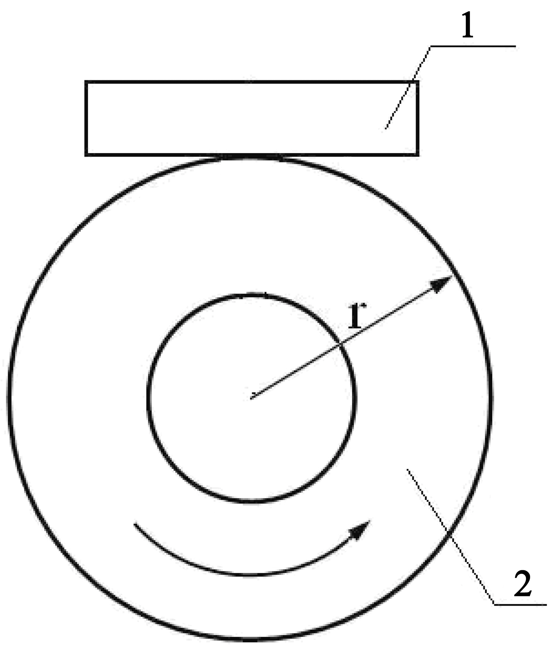
Wear test was conducted on a home-made wear tester in ambient air under dry condition. The wear tester has a rotor ring and a stator block (Fig. 1). The block specimens were C/C with the size of 20×12×6 mm, and the ring were 40 Cr steel with the size of ø40 mm outer diameter and 10 mm thickness. The wear surface of C/C was on size of 20×12 mm.All the specimens were polished using 2000# grit sandpaper
[Table 1.] Physical Properties of the C/C Composites
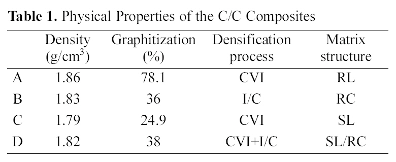
Physical Properties of the C/C Composites
followed by ultrasonic cleaning to remove debris on the surface. Testing was conducted under applied load of 60 N, 80 N, 100 N, 120 N and 150 N, respectively. The linear speed between the mates was 0.42 m/s and the test time was 5 hours. The test was repeated for 3 times.
Microstructural characterizations of the four C/Cs were observed using an inverse optical microscope with MeF3A polarizer. The degree of graphitization was measured by Xray diffraction (XRD). The worn surface of specimen was analyzed using JSM-6300LV scanning election microscopy (SEM) and NT-MDT atomic force microscopy (AFM). The size of the wear trace was measured by an optics read microscope to calculate the volume loss.
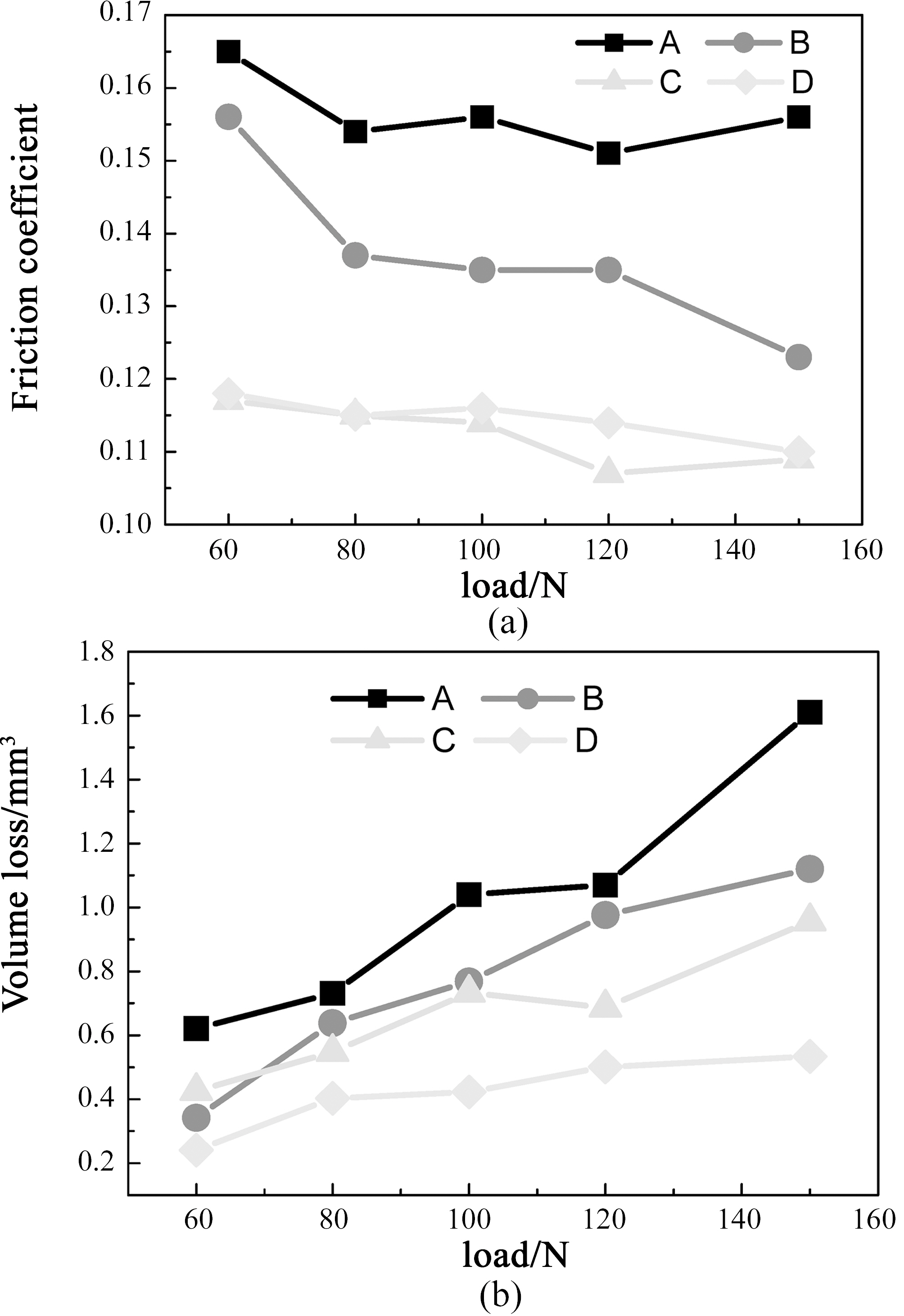
Physical properties of the four C/Cs are listed in Table 1. Effect of the matrix on coefficient of friction (COF) and volume loss is given in Fig. 2. It shows that composite A has the highest COF under all testing loads (Fig. 2a), while composite C exhibits the lowest COF. Compared with sample B, COF of composites D is less sensitive to the applied load. Under all the testing loads, the volume losses of composite A are the highest while that of composite D are the lowest (Fig. 2b).
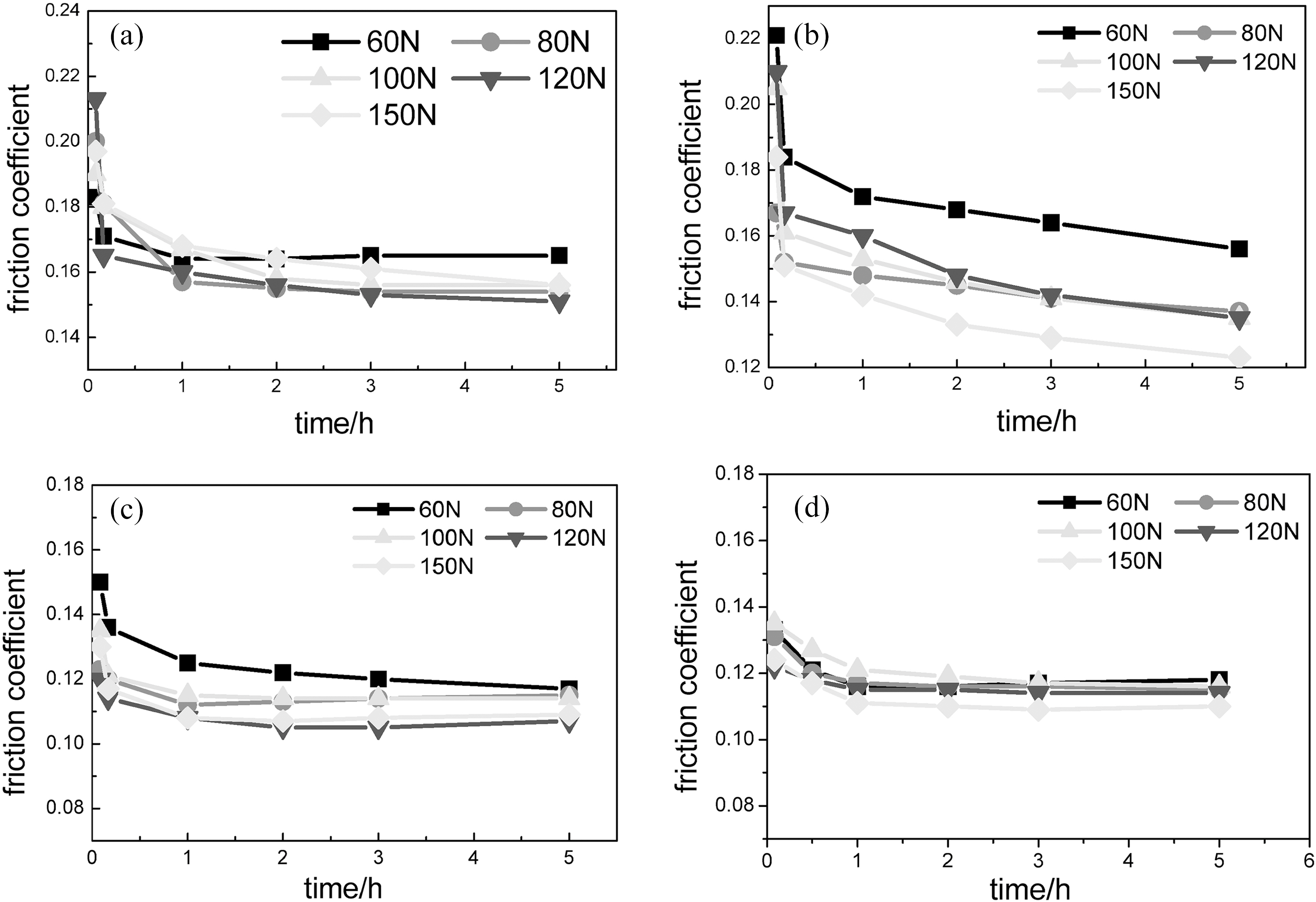
Effect of testing time on the COF is given in Fig. 3. For composite A, COF under 60 N and 80 N decrease up to1 h and thereafter remains stable, while that under 120 N and 150 N decreases with similar trend (Fig. 3a). For composite B (Fig. 3b), COF under all testing loads decrease with similar trend and appear the largest decreasing range among the four C/Cs with time. So it indicates that composite B is difficult to obtain stable frictional behavior. In the cases of composite C and D, COF remain more stable than those of composite A and B (Fig. 3c, d).
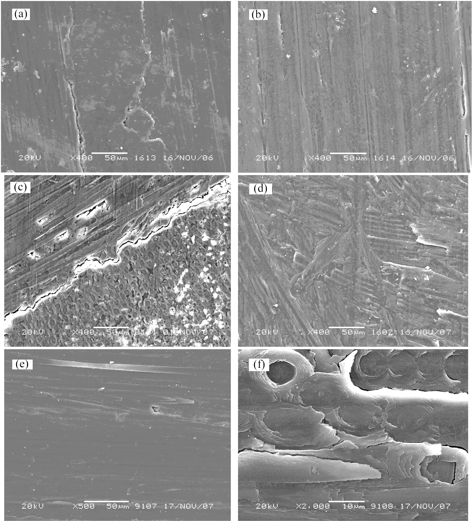
Fig. 4 shows typical SEM morphology of worn surface of composites A, C and D under 60 N and 150 N, respectively. As shown in Fig. 4a, two types of compacted friction film are formed on the worn surface of composite A tested under 60 N. One is smooth and compact film on the worn surface of fiber bundle parallel to the sliding direction; the other is thick film on the worn surface of fiber felt. However, after testing under 150 N, the worn surface of composite A becomes integrated and uniform except for some big wear
scars (Fig. 4b). Accordingly, the effect of fibers with different orientation on the worn surface might be reduced with load. However, worn fiber and big gaps between fiber bundle boundaries are formed on the worn surface of composite C under 60 N and 150 N instead of integrated film (Fig. 4c, d). In the case of composite D, although an integrated friction film is formed under 60 N, an impending fiber is found. This observation indicates that the wear resistance of fiber is higher than that of the matrix (Fig. 4e). And it directly results in the formation of micro-cracks and micro-holes at higher load (Fig. 4f).
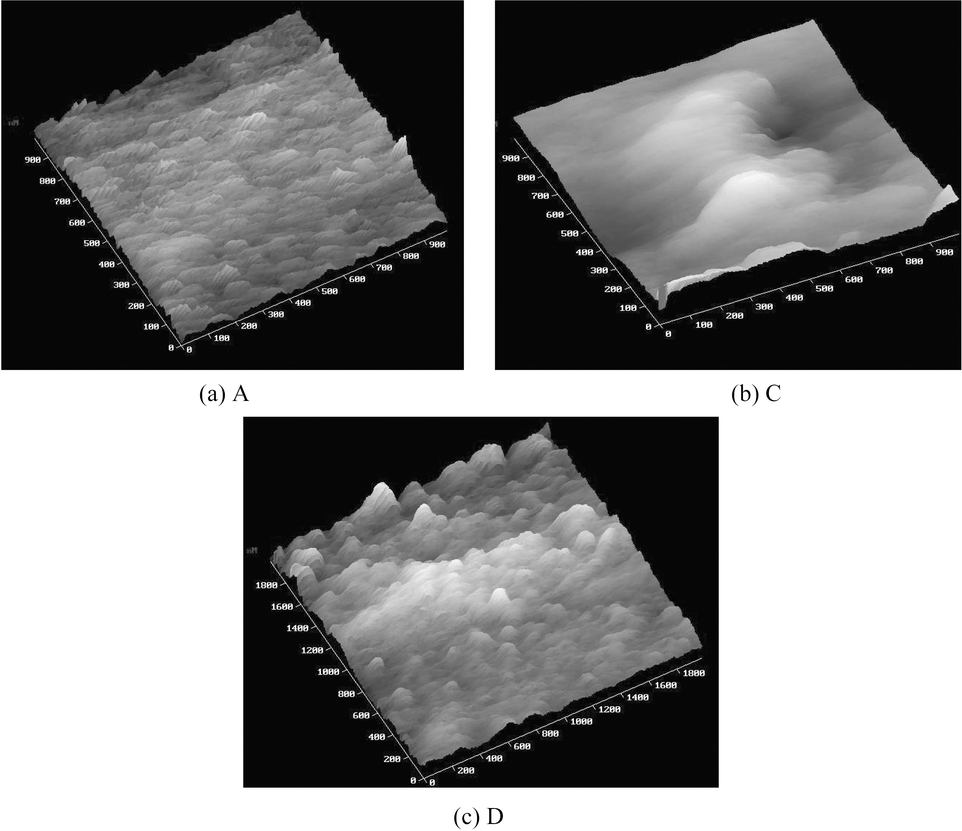
Since SEM can not reveal finer three-dimensional image, further investigation of the worn surface under 150 N was carried out for composites A, C and D with AFM, as shown in Fig. 5. It can be found that many smooth particles with the size about 100 nm exist on the worn surface of composite A(Fig. 5a). For composite C, a large particle about 400 nm was found (Fig. 5b). Whereas, worn surface of composite D, a great deal of small particles less than 150 nm are observed, (Fig. 5c). In general, the reduction in frictional resistant and COF might be partly attributed to the formation of rough
particles [3], which would limit the real contact areas between the frictional mates. Contrarily, a great deal of small and smooth particles may increase the contact area and therefore increase the frictional resistant and COF. Therefore, composite A has high COF while composite C and D have low one. Compared with composite D, the large particle on worn surface of composite C might be one reason to its slightly bigger fluctuation in the COF with load and time.
RL carbon is likely to form integrated friction film of good self-lubrication. Accordingly, composite A has stable COF with time. However, it appears that the low hardness of RL induces high COF and high volume losses of composite A. SL carbon, possessing a high hardness, limits the influence of the increasing loads, which brought out low COF and volume loss of composite C [1]. For composite B, due to the poor bonding between the RC carbon and the fibers, the worn surface of is easy to be destroyed by the fiber debris and results in the second highest COF and volume loss at the same load [4]. Whereas, with the increase of time and load, the worn surfaces become smoother and smoother, so the COF decrease gradually. For composite D, the mixed matrix has good bonding with the fibers and proper graphitization, which brought out low and stable COF and low volume loss.
The sliding friction properties of four kinds of C/C with different carbon matrix were investigated. Composite with RL matrix showed the highest COF and volume loss under the applied load of 60 ~ 150 N. Composite with RC matrix showed the highest fluctuations in the COF with time. Composite with SL matrix showed the lowest COF. Composite D with SL/RC matrix showed the second lowest COF and the lowest volume loss. Since the sliding plate and seal ring require low friction and low wear, the composite with SL/RC matrix seem to be the proper material against 40 Cr steel frictional mate.