Multi-elements doped TiO2 was prepared as a new photocatalyst in order to decrease the band gap of TiO2 by sol-gel process which can provide the large active sites of TiO2. Multi-elements were doped by using a single precursor, tetraethylammonium tetrafluoroborate (TEATFB). By the benefit of large specific surface area of TiO2 prepared by sol-gel process, catalysts showed initial fast removal of dye. The photoactivity showed that the doped catalysts significantly promote the light reactivity than undoped TiO2. The commendable photoactivity of prepared catalysts is predominantly attributable to the doping of anions which may reduce the band gap.
Removal of toxic organic compounds has been big social problems. Adsorption and decomposition is representative of the removal method. Adsorption method has some difficulties in collection and recycling of adsorbent. So, decomposition method is more effective and economical[1-5].
Photodegradation using photocatalyst is remarkable method in the degradation. Especially, Titanium dioxide (TiO2) is one of the most interesting materials in the present times as an inexpensiveness, non toxicity, and excellent optical, electronic, thermochemistrical properties. It has three commonly polymorphs in nature, those are anatase, rutile, and brookite. Anatase TiO2 is commonly showing a greater photocatalytic activity for most reactions. So, the anatase TiO2 has attracted more attention than the other two over the last decade for photocatalyst[6-10].
A good photocatalyst depends strongly on its efficiency of electron-hole pair separation and its optical absorption properties. To increase the activity of the photocatalyst, the e--h+ recombination rate should be reduced. Much effort has been focused on sensitizing anatase TiO2 by doping some transition metals or anionic dopants. Selective metal ion doping has been demonstrated to be an effective approach to separation of e- and h+. However, the transition metal dopants cause an increase of charge-carrier recombination as electron traps, and thermal instability. Furthermore, the preparation of transition metal doped TiO2 needs more expensive ion-implantation apparatuses. Recently, experimental studies revealed some anionic dopants like carbon, nitrogen, boron, fluorine. These anions doped catalyst may be more appropriate for the extension of photocatalytic activity of TiO2 than other methods because their impurity states are near the valance band edge, but they do not act as charge carriers, and their role as recombination centers might be minimized compared to metal cation doping. Doping TiO2 with an appropriate combination of anions would, of course, result in more sensitive photocatalysts for a desired application. In this context, Li synthesized N-F-codoped TiO2 photocatalysts by spray pyrolysis using TiCl3 and NH4F precursors and Suda N-doped TiO2 from TiN and TiO2 by laser ablation method. Similarly Balek reported codoping of N, F on the TiCl4 precursor with NH4F. They observed an enhanced photoreactivity of the materials. Recent studies indicate that C-N doped TiO2 materials exhibited the highest photocatalytic activity, which could be assigned to the synergistic effect of doped C and N atoms[11-24].
Another consideration of photocatalytic activity is the specific surface area and crystallite size. Large specific surface area usually helps the fast transfer of photogenerated carriers on the catalyst surface. So, it lead to fast charge transfer kinetics. Small crystallite size make nano structure it is active than bulky structure. The quantization phenomenon gives way to numerous anomalies on the particles properties, including its optical absorption, in which the decrease in particle size results in the onset of absorption shifted to shorter wavelengths (blue shift). The preparing of TiO2 from titanium precursor sol-gel method is one of the main methods for making large specific surface area and very small crystallite materials[25-30]. In this paper, we report Effect of N, B, F and C doping of titanium dioxide prepared by sol-gel process on the photodegradation.
2.1. Sol-gel synthesis of TiO2
Nanometric TiO2 was prepared by the sol-gel technique. 25 ml titanium(IV) chloride (TiCl4, Kanto chemical, Japan) were added to 300 ml 1 M hydrochloric acid (HCl, Samchun chemicals, Korea) in drops. After addition, the solution was titrated to pH 3.75 with ammonia solution (NH3, Junsei, Japan). It was stirred enough for 24 h with magnetic stirrer. After stirring, the suspension was washed with distilled water. Then, the resulting powder was heat-treated at 350℃ for 6 h in air. The calcination temperature was attained at a heating rate of 10℃/min.
2.2. Doping process of C, N, B, F
Tetraethylammonium tetrafluoroborate (TEATFB, (CH3CH2)4 N+BF4-, Sigma-aldrich, Germanny) was used for carbon,nitrogen, boron and fluorine co-doped TiO2. 20 ml 0.1M TEATFB solution and 0.05 M TEATFB solution were mixed with 3 g TiO2 made from TiCl4 individually. For comparison, commercial TiO2 (Acros organics, USA) was also mixed with 20 ml 0.1M TEATFB solution and 0.05 M TEATFB solution. The mixtures were stirred enough for 24 h. After stirring, it illuminated by microwave at 700W for 30 minutes to make C, N, B, F co-doped TiO2. Then, the resulting powder was washed with distilled water to remove undoped salt and was dried at 110℃. The details of the samples are presented in Table 1.
A Scanning Electron Microscope (SEM, JSM-6300, JEOL Ltd, Japan) was used to explore the surface properties of the samples under 20 keV. The SEM analysis was conducted by a gold- palladium sputtering process. The crystalline phases of samples were determined by X-ray diffraction (XRD, D/MAX-2200 Ultima/PC, RigaKu, USA) with Cu Kα radiation. The specific surface area (BET) of the catalysts was measured by N2 adsorption-desorption studies at 77 K using (Micromeritics
[Table 1.] The Details of the Samples
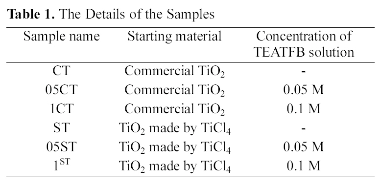
The Details of the Samples
ASAP 2020, USA). Prior to the analysis, samples were degassed at 473 K for 3 h. The X-ray Photoelectron Spectroscopy (XPS, MultiLab 2000 spectrometer, Thermo electron corporation, England) spectra were obtained with Al Kα excitation to know the changes of chemical species on the samples’surface before and after doping process.
2.4. Photodegradation performance
UV-vis spectrometer Mecasys (Optizen 2120 UV) was used for absorbance measurement. The photocatalytic activities of the samples were evaluated by measuring the change of the concentration of procion blue dye (PB, Acros organics, USA) solution at 600 nm during the photocatalytic decomposition. The experiments were performed using Pyrex glass beaker of 250 ml (68.0 mm in diameter and 94.6 mm high) with a UV lamp (ENF-240C, Spectroline spectronics company,USA) on batch type. The initial PB solution was kept on 100 ml of 100 ppm. Each 0.1 g of the catalysts was added into the solution. The samples of PB solution were illuminated by UV lamp of wavelength 365 nm with 4W during stir. 3 ml of the suspension were collected at regular time periods during irradiation and filtered through 0.45 ㎛ polytetrafluoroethylene (PTFE) syringe filter (Whatman, England) to remove suspenses.
3.1. Physicochemical characterization
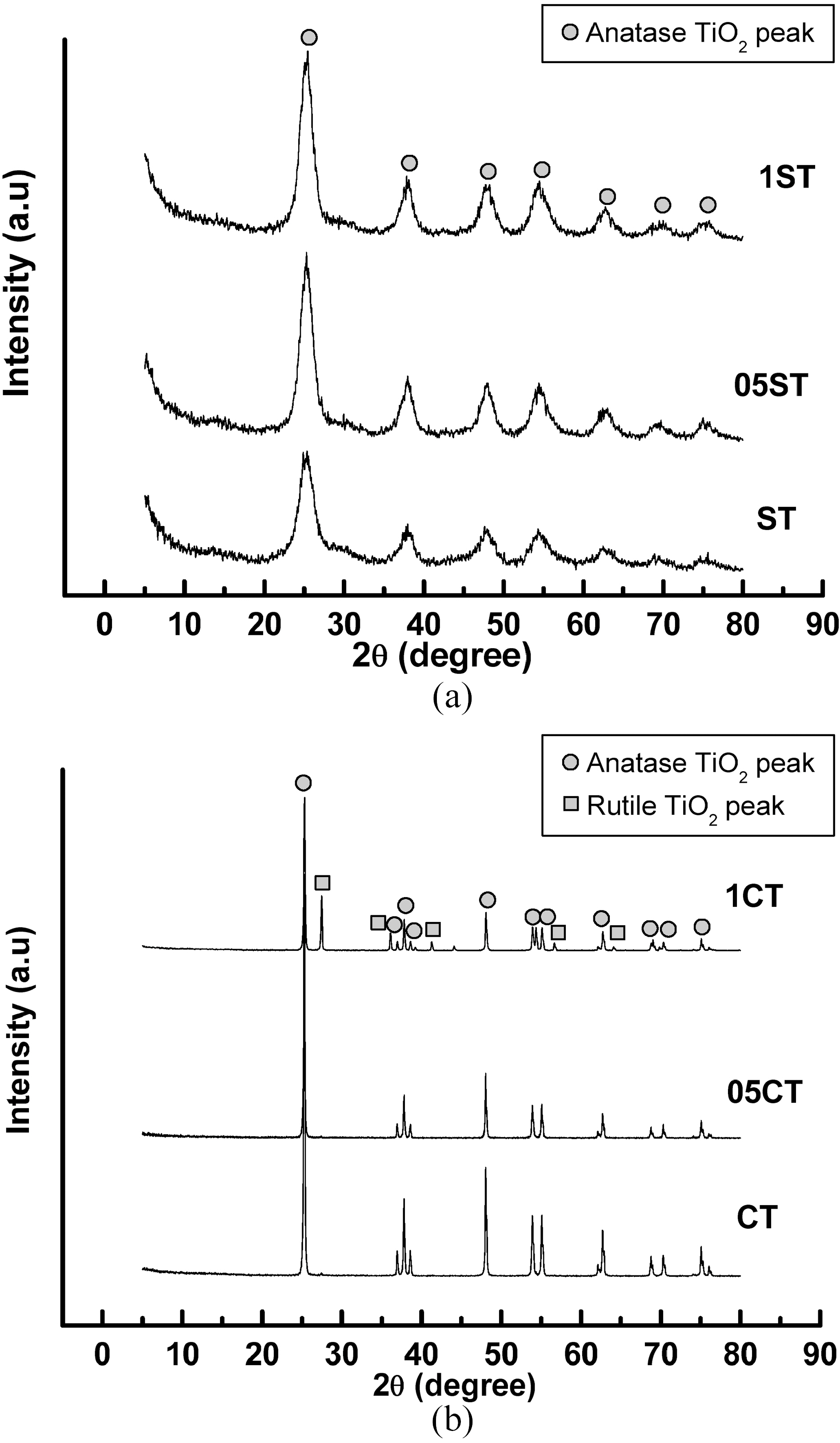
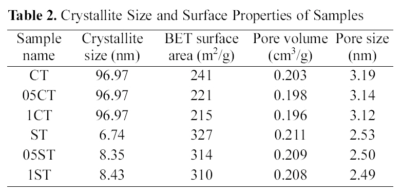
The XRD patterns of TiO2 powers synthesized by the solgel method and commercial TiO2 are shown in Fig. 1. The XRD patterns of the all catalysts contain main anatase peak (2θ =25.3°) and minor anatase peak (2θ =37.0°, 37.9°, 38.5°, 48.1°, 54.0°, 55.2°, 62.2°, 62.8°, 68.5°, 70.5°, 74.0°, 75.0°, 76.0°) as the predominant homogeneous crystalline phase and only 1CT contains some rutile peak (2θ =27.5°). These show that crystalline anatase phase was formed from amorphous phase by heat treatment. And these are no shift in the peak position caused by the C, N, B and F doping, suggesting that dopants of anion are uniformly distributed on TiO2 surface. The crystallite size of TiO2 (Table 2) is obtained from the largest peak at 2θ=25.3° by using Scherrer’s formula D=0.9λ/β?cosθ, where λ is the wavelength of the X-ray at Cu Kα radiation (θ=0.15418 nm), θ is the diffracting angle, andβ is the line-width at half-maximum (FWHM). It is well known, that the crystal phase and crystallite size are crucial factor for the photocatalytic activity of photocatalyst. It is observed that the crystallite size of samples made from solgel method is much smaller than commercial TiO2 and decreases with concentration of doping agent. The reason of various crystallite sizes according to concentration of doping agent in preparation by sol-gel method is that doping species
[Table 2.] Crystallite Size and Surface Properties of Samples

Crystallite Size and Surface Properties of Samples
have an effect on TiO2 crystallite sintering, leading to bigger crystallites than non-doped it. That is the lattice parameters changes little after doping in TiO2 particles. It is inferred that C atoms are difficult to weave into the TiO2 lattice, and most exist on the surface of TiO2 nanoparticles and form a layer of complex carbonate species. In other word, the crystallite
size increase in the presence of dopants, as they could possibly interact with the TiO2 network, and thus help the growth of the crystal. Even a small amount of the dopants species is sufficient for this effect. Therefore, the change in concentration of doping agents don’t exert influence seriously on crystallite sizes[31].
Pore volume (single point adsorption total pore volume of pores at P/P0 =0.99), pore size (determined from BET adsorption average pore width), and BET specific surface area of samples are given in Table 2. The samples prepared
[Table 3.] Atomic Composition of the Catalysts Measured by XPS (at%)
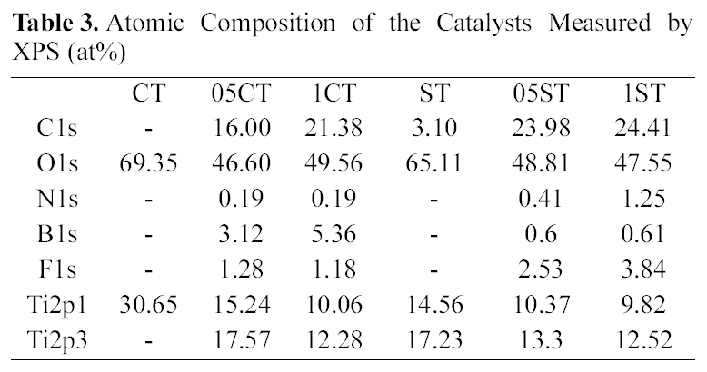
Atomic Composition of the Catalysts Measured by XPS (at%)
by sol-gel method have much larger specific surface area than commercial TiO2 because the method creates nano particle and nano structure. Moreover doping modification leads to decreasing specific surface area, average pore size, and total pore volume of the catalysts. The small decreasing in pore size and pore volume after doping process is due to filling of pores to form small pores[32].
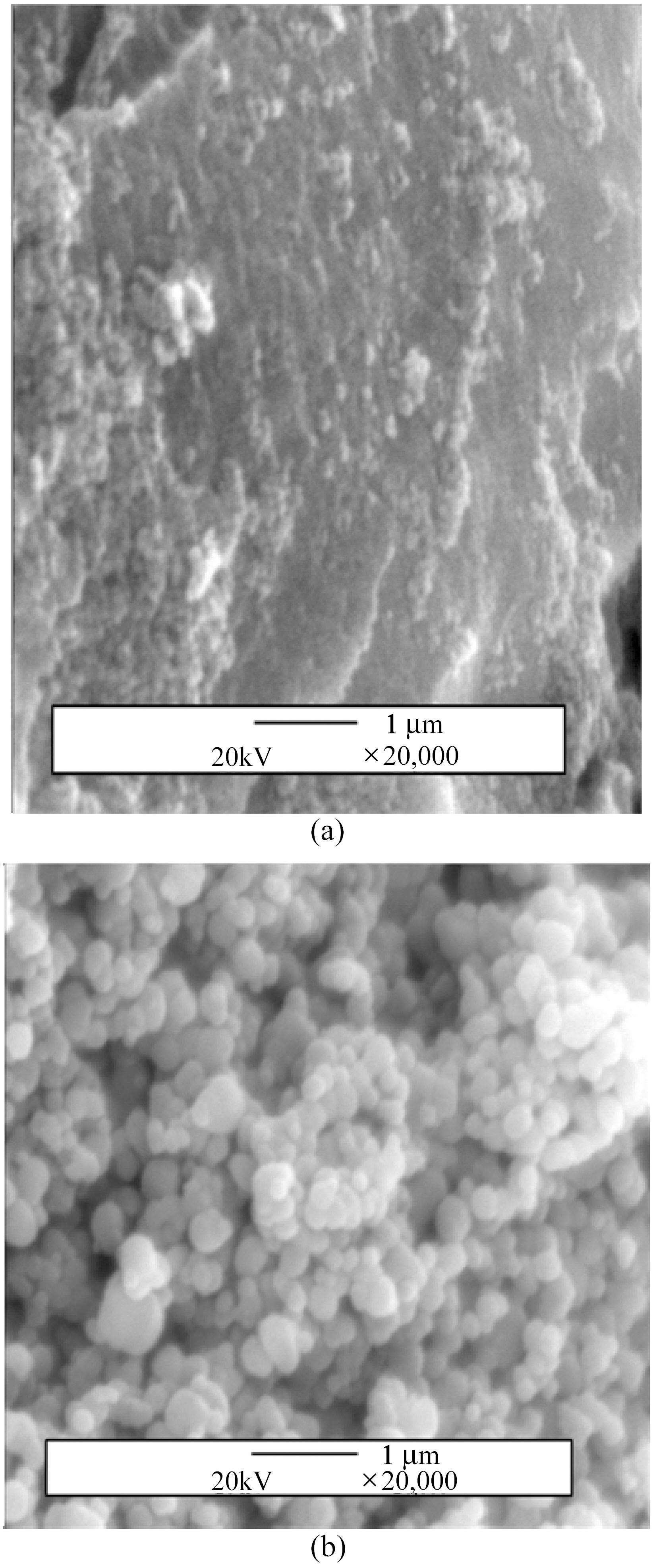
SEM micrographs of commercial TiO2 and TiO2 made from
TiCl4 by sol-gel method are shown in Fig. 2. The particles were found to be in uniform spherical shape with average particle size of 0.2~0.3 ㎛ and rough surface in ST whereas in irregular shape as aggregation and flat surface in CT.
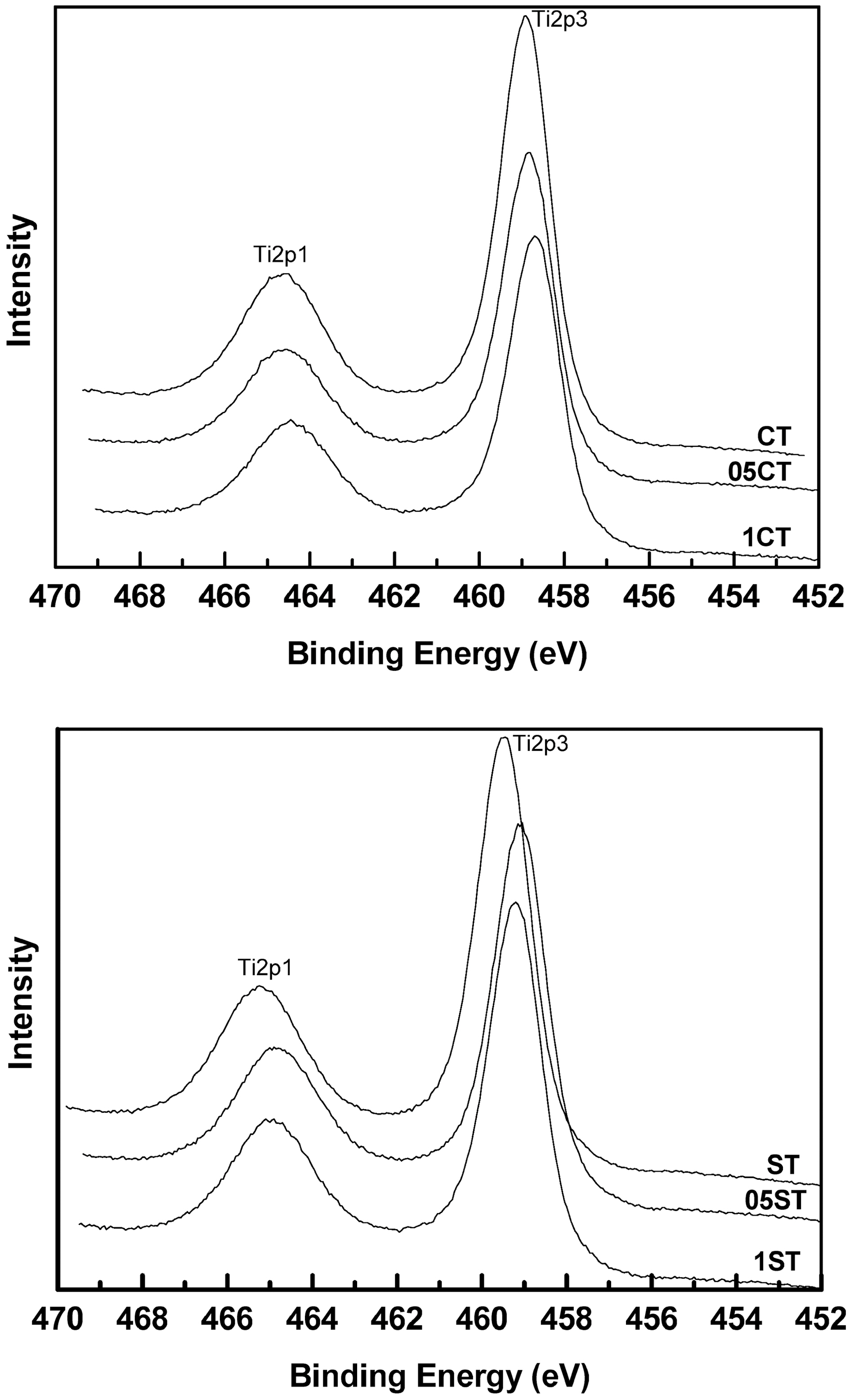
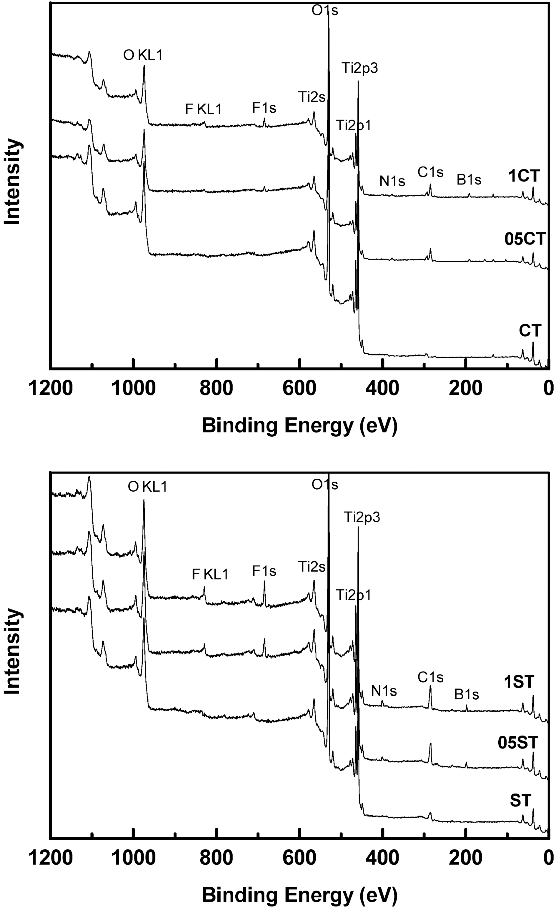
Fig. 3 and Table 3 show the XPS survey spectrum and the atomic composition of the catalysts respectively. The XPS binding energies of the core level in all the samples indicate the successful incorporation of the dopants into the lattice. The results show that all the doped samples have C, N, B and F elements, whereas it is absent in undoped TiO2. On the whole, atomic weight percents of dopants increase according to increment of TEATFB solution's concentration. The XPS spectrum of Ti 2p levels of the catalysts are shown in Fig. 4. They have two peaks mainly around at 459 eV, Ti2p3/2 and 465 eV, Ti2p1/2. The data remained on an octahedral anatase TiO2[33]. Also, the increasing of concentration of TEATFB solution leads peak position shift to lower binding energy because impregnation and doping of the dopants like C, N, B, F. The binding energy of functionalized anatase TiO2 is
affected by the polarity of dopants[34].
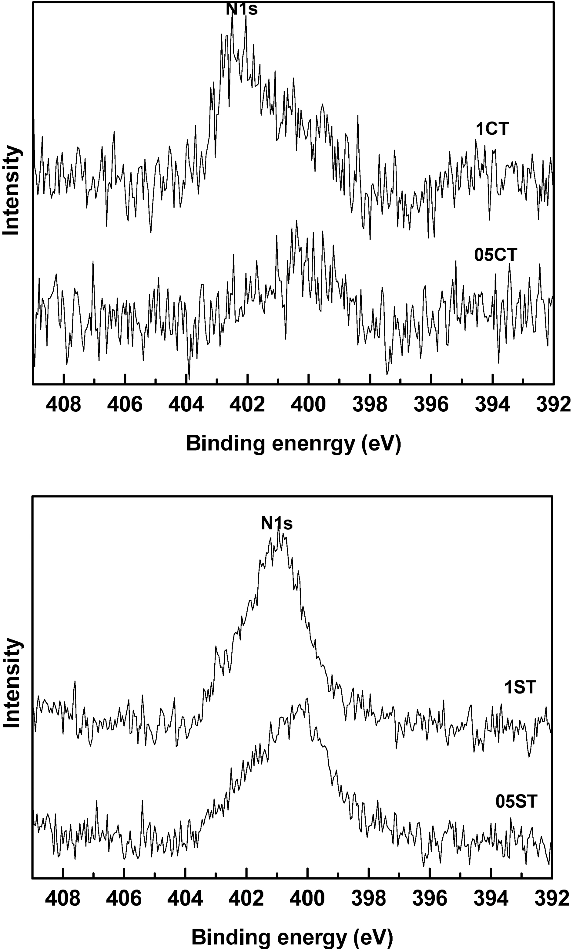
The XPS spectrum of N1s levels of the catalysts are shown in Fig. 5. The active site and nitrogen state are responsible for the enhanced photocatalytic activity of nitrogen-doped TiO2. The N1s peak around at 401 eV was observed in all the doped catalysts. Similarly, a significant peak around at 402 eV and a minor peak around at 400 eV assign to N1s peak in doped TiO2. In literature nitrogen doped TiO2 was observed the binding energy at 400.1 eV. It assign to hyponitrite at the surface, which attributed to the doped nitrogen into the TiO2[34]. The N1s peaks of the catalyst prepared by gel-sol method are higher and sharper than commercial TiO2. Because of the larger specific surface area of the catalyst prepared by sol-gel method 05ST and 1ST have more active site for doping. The results are shown same with Table 3.
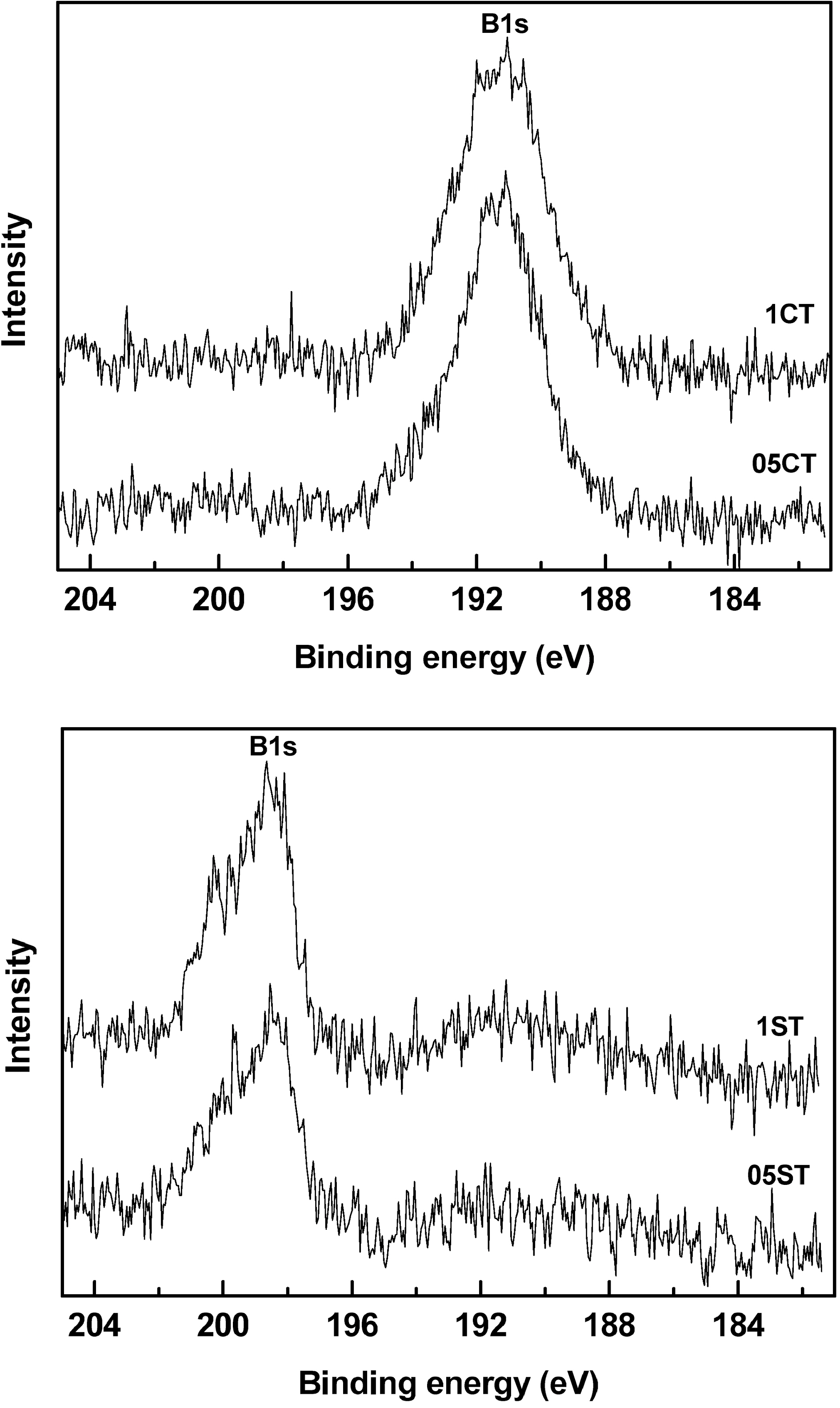
Fig. 6 shows the XPS spectra of B1s region on the surface of the samples. It is observed that the B1s region contains at 198.65 (05ST, 1ST) and 191.05 eV (05CT, 1CT) because of
the binding energy shifts from 187.5 eV. This implies the formation of weak bond in Ti-B due to interferential effect of other elements bonded with Ti. Taking into account the standard binding energy of B1s in TiB2 (187.5 eV, B-Ti bond), this result displays that the boron atom is probably incorporated with TiO2 to some extent, and the chemical environment of the surrounding boron is similar to that of TiB2[35]. The peak position of 05ST and 1ST are shifted much bigger than 05CT and 1CT. These show B atoms are incorporated with TiO2 easily in 05ST and 1ST having high specific surface area and active site than 05CT and 1CT. In Table 3, catalysts prepared by sol-gel method have high dopant surface contents of C, N, F. However the boron surface contents of 05ST and 1ST is smaller than 05CT and 1CT because of the easy incorporation with TiO2 in 05ST and 1ST.
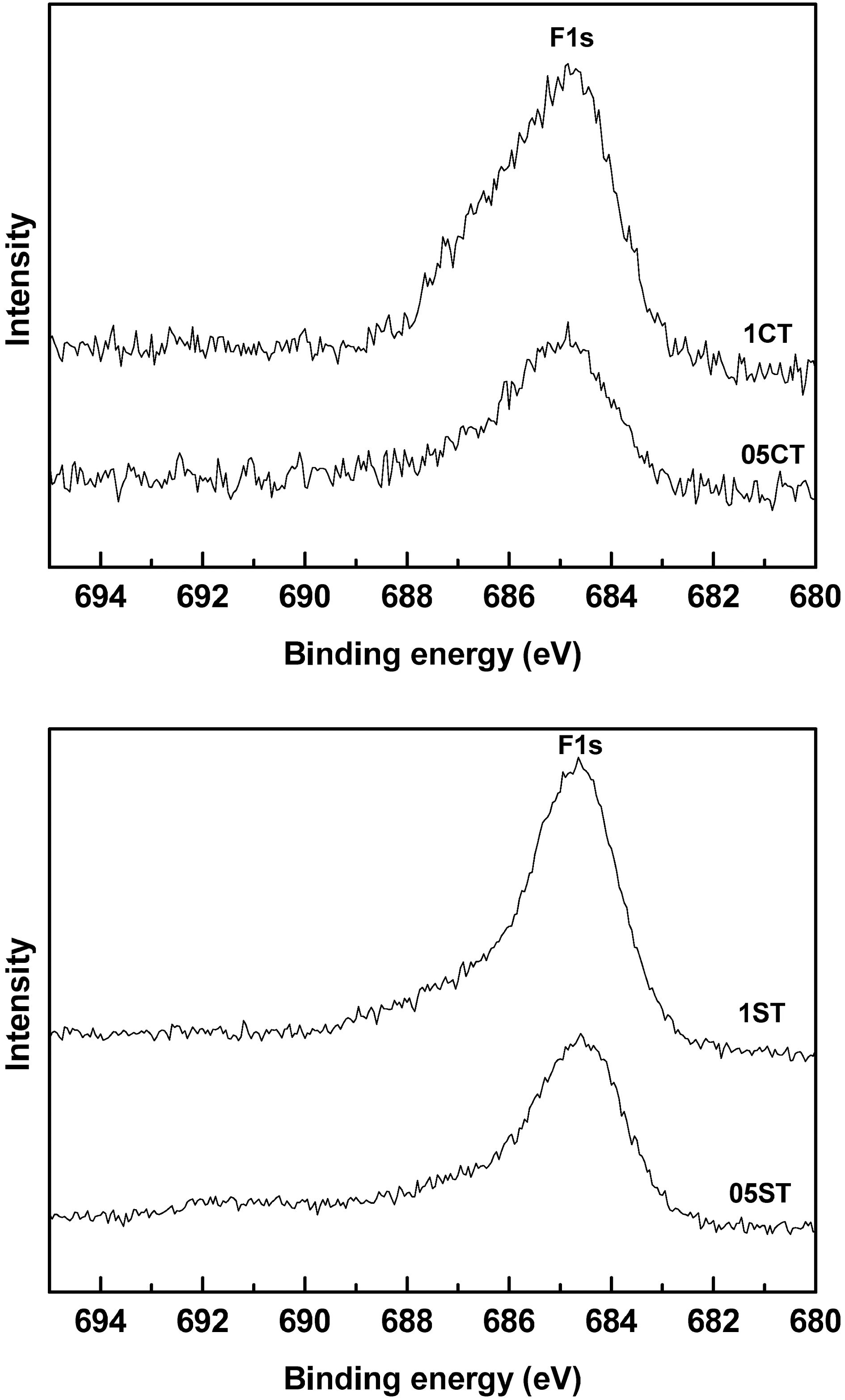
Fig. 7 shows the F1s XPS spectra of the doped samples. The main peak of the asymmetrical shape at around 684.7 eV
in F1s spectrum can be assigned to structures containing oxyfluoride (F-Ti-O) functional groups while the shoulder at 686 eV is connected to F-Ti bond. These reveal that fluorine is incorporated in the TiO2 by substitution of oxygen atoms in its lattice and TiO2-xFx structures are formed at surface of catalysts. The sharp clear peak is shown in 05ST and 1ST but broad crooked peak is shown in 05CT and 1CT owing to unstable incorporation (complex binding) as well as low contents.
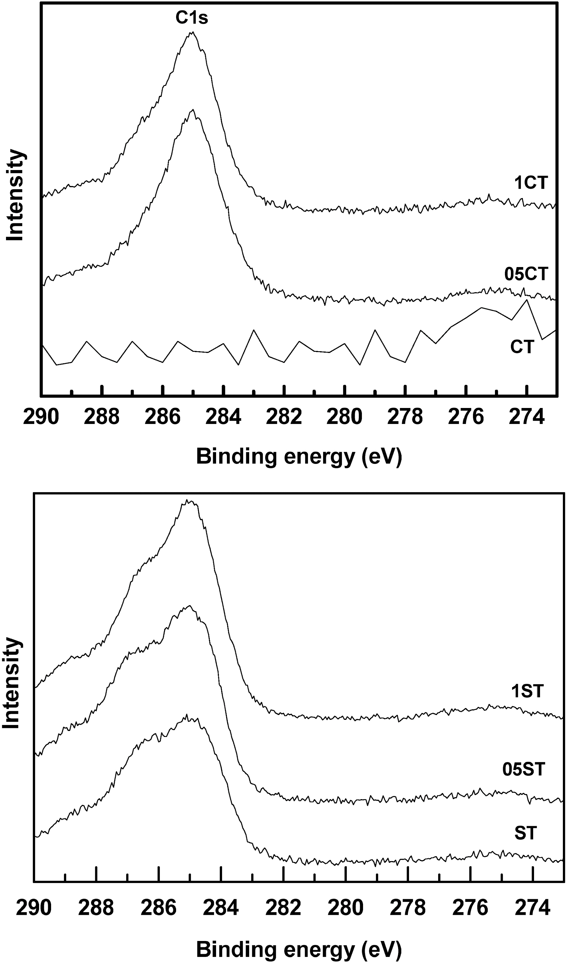
Fig. 8 shows the C1s XPS spectra of the doped samples around 285 eV. The CT is shown no noteworthy peak because it is a pure TiO2. However, ST has small broad C1s peak with shoulder. The C1s peak of ST seems to be formatted by binding during heat treatment with CO2 or organic matter in air. In the case of C and F there is no observable peak shift. These trends are shown the bonds of Ti-C and Ti-F are not influenced by the other polarities of dopants. These can be suggested that bonds of F, C atoms with Ti are stable[36-40].
3.2. Application studies in dye degradation
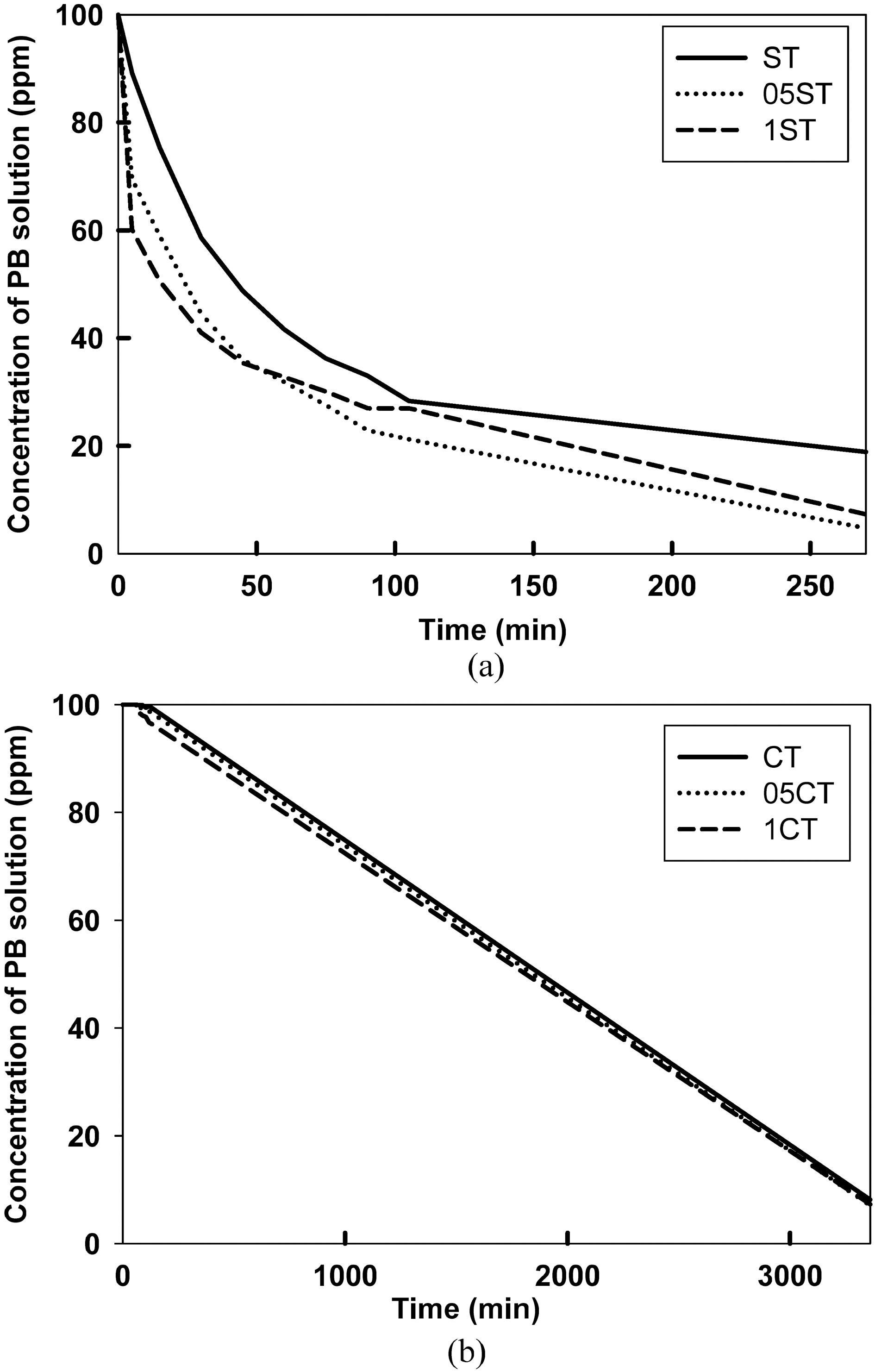
To explore the photocatalytic activity of the photocatalyst,removal of procion blue dye were investigated. Fig. 9 (a) and (b) illustrate the photoactivity of the prepared samples by sol-gel method and commercial catalyst on the degradation of the dye according to reaction time with UV. The adsorption efficiency of the dyes on to the catalyst surface was observed in initial rapid decrease of the solution concentration. It is evident from the change of color on the surface of catalysts. In the case of doped samples the adsorption is found out much clearer than undoped samples. The photocatalytic activity can be observed from slope of the concentration. After 4 h of exposure to the samples, more than 80% dye was removed in 05ST, 01ST and more than 70% in ST, whereas only less than 10% dye was removed in CT, 05CT, and 1CT. In the result the prepared samples by sol-gel method shows higher photocatalytic activity and adsorption in short time, comparing with commercial
samples due to high specific surface area, more amounts of dopants and small crystallite size. The increasing surface area and the decreasing crystallite size increase substantially the amount of dye degradation. Particularly in the catalyst made by sol-gel method, the sensitization of TiO2 plays an important role. These nano materials indicate a superior adsorption capacity for the photocatalyst. The 05ST and 1ST have the highest photocatalytic activity, as a higher specific surface area, smaller crystallite size than commercial catalysts and more amounts of dopants than undoped catalysts.
3.3. Effect of C, N, B and F as dopants
In order to study the effect of the dopants, doped TiO2 were attempted with 0.05 and 0.1 M TEATFB solution. Degradation graphs of dyes reveal that 0.05, 0.1 M TEATFB doped TiO2 catalysts (05ST, 1ST and 05CT, 1CT) showed similar degradation efficiency. Hence, a small amount of dopants act enough as reducing of band-gap energy.
The results report that the C, N, B and F doped TiO2 degrades concentration of dye faster than undoped TiO2 because it enhances activity of TiO2. The doping of C, N, B would narrow the band gap by the replacement of one O atom with the doping atoms. The fluorine doping can generate oxygen vacancies in TiO2. It is well known that oxygen vacancies in a solid make the limit of surface photochemical processes on red-shift to visible region[15, 40-42].
The doped samples have smaller specific surface area than undoped samples because of surface dopants. However the doped samples show the higher adsorption efficiency than undoped samples and 0.1M TEATFB doped samples (1ST,1CT) show the higher adsorption efficiency than 0.05M TEATFB doped samples (05ST, 05CT). The obtained results suggest that the carbonaceous species at the surface of doped samples could absorb more dye molecules than the undoped TiO2. When the absorbed dye molecules are degraded, other dye molecules are adsorbed on the carbonaceous layer. It can transfer to the residual vacancies through surface diffusion, which is faster process than free diffusion in solution. It is well known that the organic substance should be preconcentrated on the surface of the semiconductors to utilize the photo-excitations effectively for effective degradation.
The catalysts made by sol-gel method with TiCl4 show a better performance on the adsorption and photocatalytic degradation of PB solution than commercial TiO2 because of mainly high specific surface area and small crystallite size. Besides prepared anions like C, N, B and F doped TiO2 from a single precursor (TEATFB solution) shows more effective photoactivity and adsorption than non-doped TiO2. XRD, SEM and XPS analysis corroborate that these doped materials are prepared and they are homogeneous anatase crystalline phase. The dispersed anions promote the electron hole separation and subsequently enhance the photoactivity.