The carbon material is normally produced through the heat treatment of organic materials such as phenolic resins, furan resin, or pitch. When a pitch is heat treated, it converts into cokes via a pyrolysis process with the volatilization of a lowmolecular material in a liquid state.
In this heat-treatment process, isotropic liquid pitch develops into mesophase [1]. The liquid crystal produced at this stage causes nucleation in liquid pitch, and the liquid crystal grows based on coalescence.
In this process, the part of the pitch that is not converted into mesophase remains as isotropic pitch. The converted liquid mesophase forms bulk mesophase during the consistent heat treatment and converts into graphitizable solid soft cokes at a high temperature. Prior to the formation of bulk mesophase, the mesophase exists as a spherical, and this spherical mesophase separated from the isotropic pitch is known as mesocarbon microbead [2,3]. This mesocarbon microbead has attracted considerable attention lately as a precursor of a carbon material with an outstanding property.
The mesocarbon microbead is used for manufacturing of high density carbon [4], column packing material [5], electrode material of lithium ion rechargeable batteries [6-8], superactive carbon [9,10], and carbon materials with improved mechanical strength [11,12].
A number of methods for manufacturing of the mesophase microbead have been introduced [13-22]. However, an important factor in producing this microbead was to decrease the distribution of particle sizes and high yield.
Regarding the course of manufacturing a carbon/carbon composites derived from the pitch, a carbon-fiber preform is impregnated into molten pitch, and graphitization is performed after pressurized carbonization to form a carbon matrix in the preform, this graphitization to repeats the densification process to gain the composites. In this case, most of the pitch is converted into soft cokes through a bulk mesophase course and is converted into a graphite structure with strong anisotropy through the course of graphitization. However, the carbon matrix must exhibit isotropy when needed to be suitable for its applications.
The carbon/carbon composites used in a rocket nozzles and nose cone in the space industry requires isotropy. Therefore, a reinforcing arrangement of carbon fiber, becomes more suitable for this use the more it exhibits multidirectional isotropic structures and the isotropy of a carbon matrix. Accordingly, the pitch fused in the course of the densification of a carbon fiber preform must allow the moderate growth of a liquid crystal. The further growth and the conversion of bulk mesophase must then be suppressed. When a consistent heat processing is performed, the liquid mesophase converts into fine grained cokes, and when the final graphitization is performed, the carbon matrix of the carbon/carbon composites forms based on the fine grain. Thus, the
[Table 1.] Characteristics of carbon fiber used as reinforcement
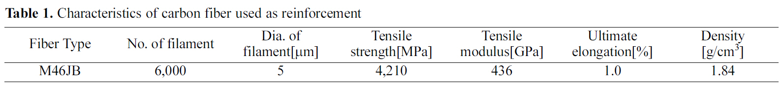
Characteristics of carbon fiber used as reinforcement
[Table 2.] Characteristics of pitch used as matrix precursor

Characteristics of pitch used as matrix precursor
isotropic composites can be produced macroscopically.
In this research, pressure is used as a method of suppressing the growth of the liquid mesophase produced in the course of high densification. A high pressure in the system result in, high viscosity of the molten pitch, preventing the liquid crystals form coalescing due to the restricted fluidity of the crystal. As a result, the conversion into bulk mesophase is impossible, and a base consisting of fine spherical grain can be gained. Thus, an isotropic carbon/carbon composites can be manufactured.
The carbon fiber used for the manufacturing of a carbon/carbon composites was M46JB(Toray Industries, Japan) and the basic properties of this fiber are shown in Table 1.
The coal-tar-pitch matrix precursor used to form a carbon matrix in carbon fiber preform was a product of OCI Co., Ltd, and its properties are shown in Table 2.
2.2. Fabrication and Impregnation of the Carbon Fiber Preform
Carbon fiber preform is fabricated with 3 directions and the axis of a fiber is weaved so that the x/y/z directions cross each other at right angles(90°). For the weaving, two upper/lower plates containing a hole of the size of preform unit cell are fixed to the ring support, and the holes on the upper/lower plates are filled with a metal rod. Initially, a layer is created by recharging a fiber bundle in between metal rods in the x direction, and then another layer is created on top by recharging a fiber bundle in the y direction to mutually cross the x and y layers at right angles. When the x layers and the y layers accumulated to the preferred height, each of the metal rod is replaced with a fiber bundle to recharge the fiber in the z direction. Next, these layers cross at right angles, and threedirectional fiber preform is manufactured. The detailed manufacturing method has been reported elsewhere [23-25]. The density of manufactured preform is 0.86 g/cm3, and the volumetric ratio of the fiber is 48.0 vol.%.
To impregnate the manufactured preform into molten pitch, the preform is placed into a metal container and a sufficient amount of powder pitch is added so that the preform can be submerged when the fusion is performed. Next, the preform is placed into an autoclave and heated while sustaining the decompression status in the system. In this course, the pitch is fused, and its partially volatile content is removed. The autoclave internal pressure and the temperature are maintained at 10 MPa and 230℃, respectively, for 20 hours to effectively impregnate the molten pitch into the preform, and part of the pitch is pyrolyzed to initiate a polycondensation reaction.
2.3. Pressure Carbonization & Graphitization
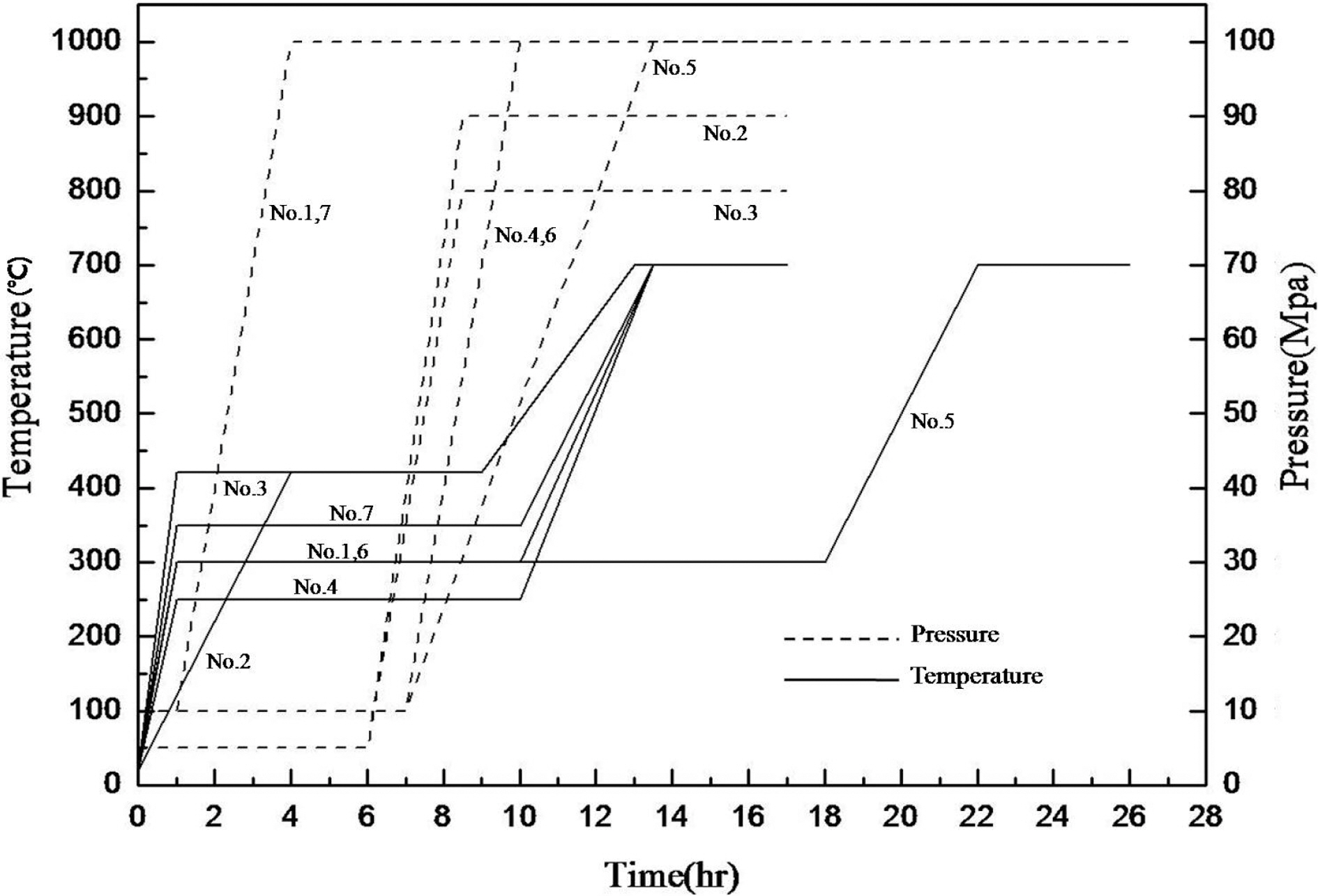
Hot isotatic press(HIP) equipment was used for the pressure carbonization. A specimen with completed impregnation was inserted into the HIP equipment and heated, while the internal pressure was adjusted to 10 MPa for pitch melting. After the set temperature was reached, it was maintained for a long time and the internal pressure of the HIP equipment was slowly increased to 100 MPa.
The pressure carbonization increases the carbon yield gained from the pitch, and thus, high pressure is required. Accordingly, it has merits of maximizing the high densification efficiency.
The temperature and the pressure of the pressurecarbonization course as well as the profile of retention time are shown in Fig. 1.
The specimen carbonized in the HIP equipment was processed at up to 2800℃ in a graphitizing brazier for the graphitization of the carbon matrix. In this case, the heat treatment was as follows. The carbonized specimen was placed into a graphitizing furnace, and the atmosphere was replaced with an argon gas atmosphere. The temperature was raised to 600℃ in 2 hours, from 600℃ to 1000℃ in 20 hours, from 1000℃ to 2500℃ in 21 hours and from 2500℃ to 2800℃ in 3 hours. Finally, the temperature was maintained at 2800℃ for 30 minutes prior to the completion of graphitization.
2.4. Fine Structure Observation
S-4800 SEM from Hitachi High-Technology Corp.(Japan) was used to examine the fine structure and morphology of the specimen. After the surface of the specimen was polished, it was cleansed using an ultrasonic instrument (EW-8892, Cole-Parmer, USA) and dried for surface observation.
3.1. Fine Structure of Pressurized Carbonized Specimen
The carbon-fiber preform and the raw pitch powder were placed into HIP equipment, and high densification was performed. The dwell temperature was 300℃ and was maintained for 9 hours. The atmosphere pressure was 100 MPa.
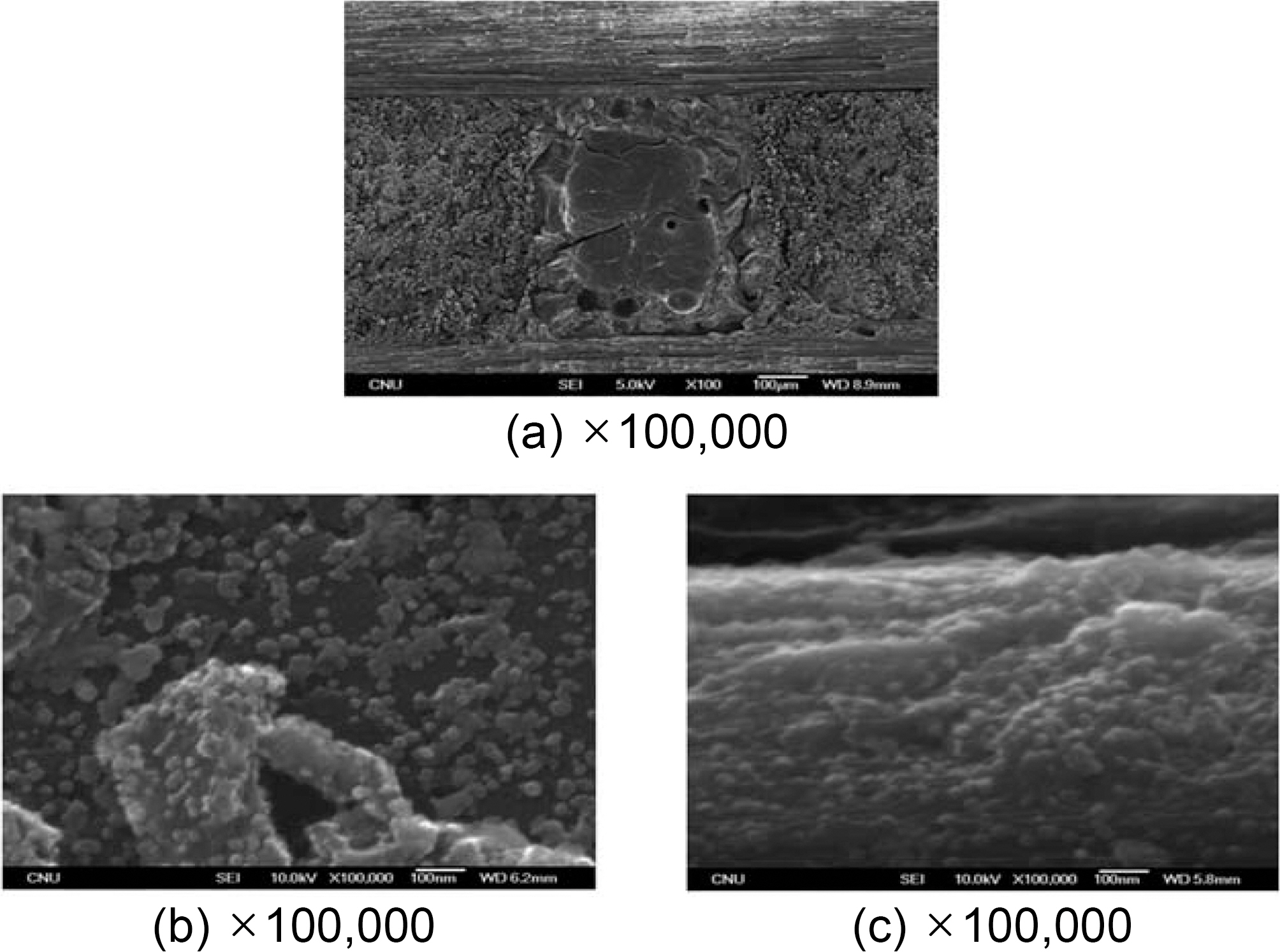
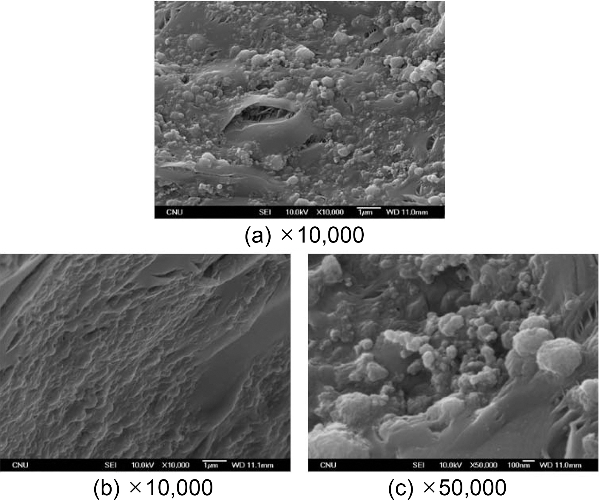
The SEM image obtained under conditions without graphitization,
In the center of picture (a) in Fig. 2, the matrix pocket is
placed and a reinforced fiber bundle surrounds it. No significant any crack was detected on the surface at the interface either between the fiber bundle and the bundle or between the fiber bundle and the matrix packet. The matrix pocket is well-filled with cokes as well.
However, a few cracks and spherical bubble pores produced by high densification were detected.
Picture (b) shows the internal section of a matrix pocket magnified 100,000 times. In this picture, a considerable amount of fine spherical grains was found. The size of the grains is approximately 30 nm.
There are 6,000 monofilaments the fiber bundle, and picture (c) shows the surface of these monofilaments. This fiber surface exhibits a fine structure consisting of particles. The size of these spherical grains is also approximately 30 nm.
This spherical grain demonstrates a growth through the nucleation and coalescence of the mesophase nucleus in the isotropic molten pitch. However, its growth speed is probably quite insufficient because the viscosity of molten pitch significantly increased and its fluidity is restricted due to a high pressure, e.g. 100 MPa of atmosphere pressure.
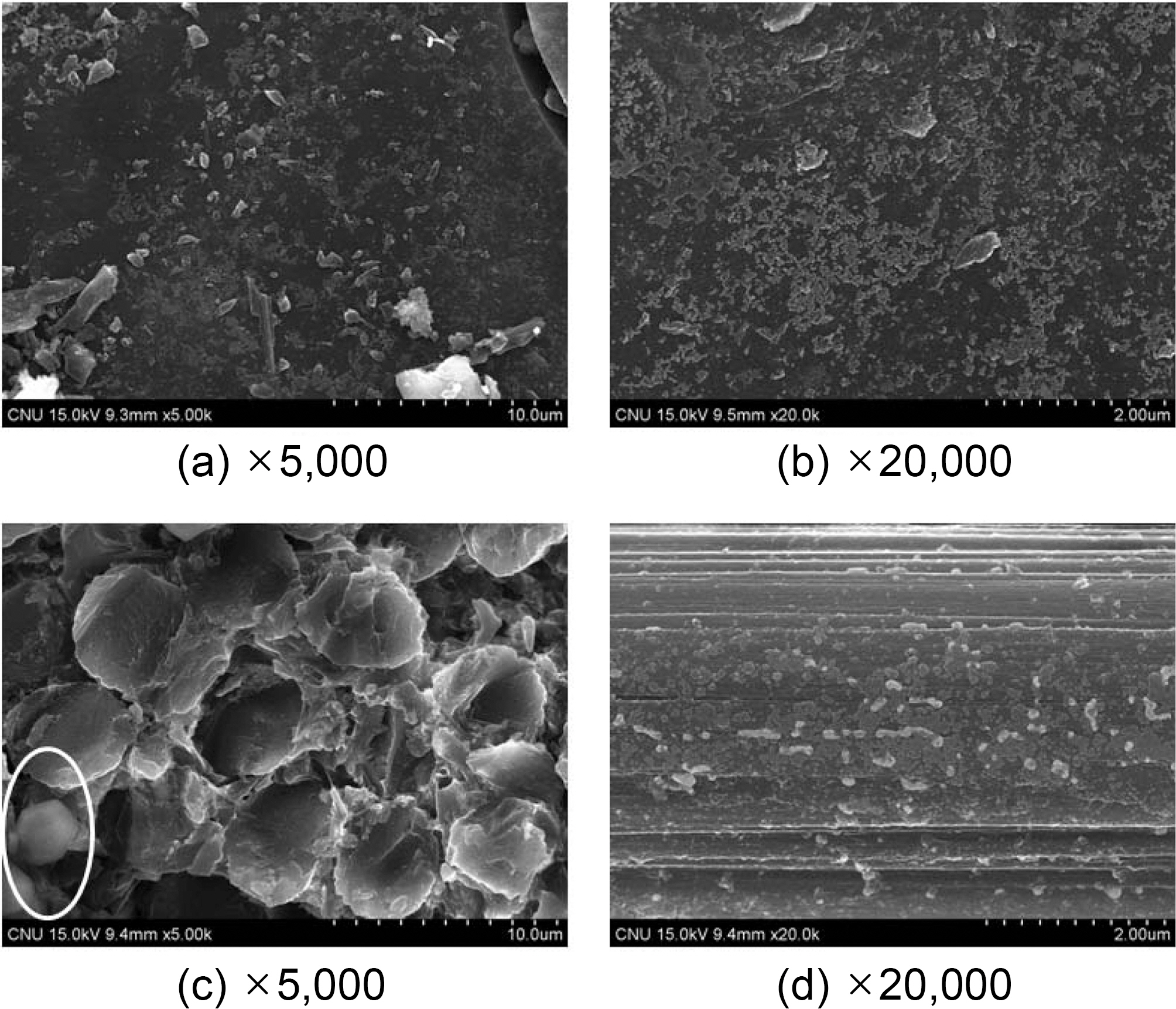
Fig. 3 exhibits a picture of a specimen with completed courses of densification based on HIP cycle No. 2 for pressure carbonization and of impregnation process at 350℃ for 20 hours. This specimen is not yet graphitized.
The background of pictures (a) and (b) seem to be amorphous cokes. However, many grains exist here, and when the focus is accurately adjusted, the amorphous background consists entirely of grains.
In picture (a), the crushed grains are larger than the spherical grains. The longer directional distance of a crushed grain seems to be approximately a few ㎛ in size. These grains may be produced by the coalescence of fine spherical grains. Normally, when nuclei are produced, they interact and mutually coalescence into spheres. However, the crushed grains that are not spherical are probably created by fine spherical grains encountering one another and partially coalescing. This phenomenon is estimated to occurs because high pressure, such as 100 MPa is applied and increases a viscosity of the molten pitch which eventually disturbs the normal coalescence of the spherical grains.
Picture (c) shows a fiber bundle cross section. In this photograph, the cokes are well-formed within the fiber bundle. The cokes surrounding the monofilament seem like glass, which is completely different from the laminated structure of graphite. In addition, a spherical grain is found in the lower left section of the picture.
In picture (d), the fiber surface is covered with spherical grains. The grain size is mostly submicron, but 1~2 ㎛ grains are also reasonably common.
3.2. Fine Structure of Graphitized Specimen
A specimen carbonized up 100 MPa and 1000℃ was graphitized up to 2800℃. Next its structure was examined through an electron microscope.
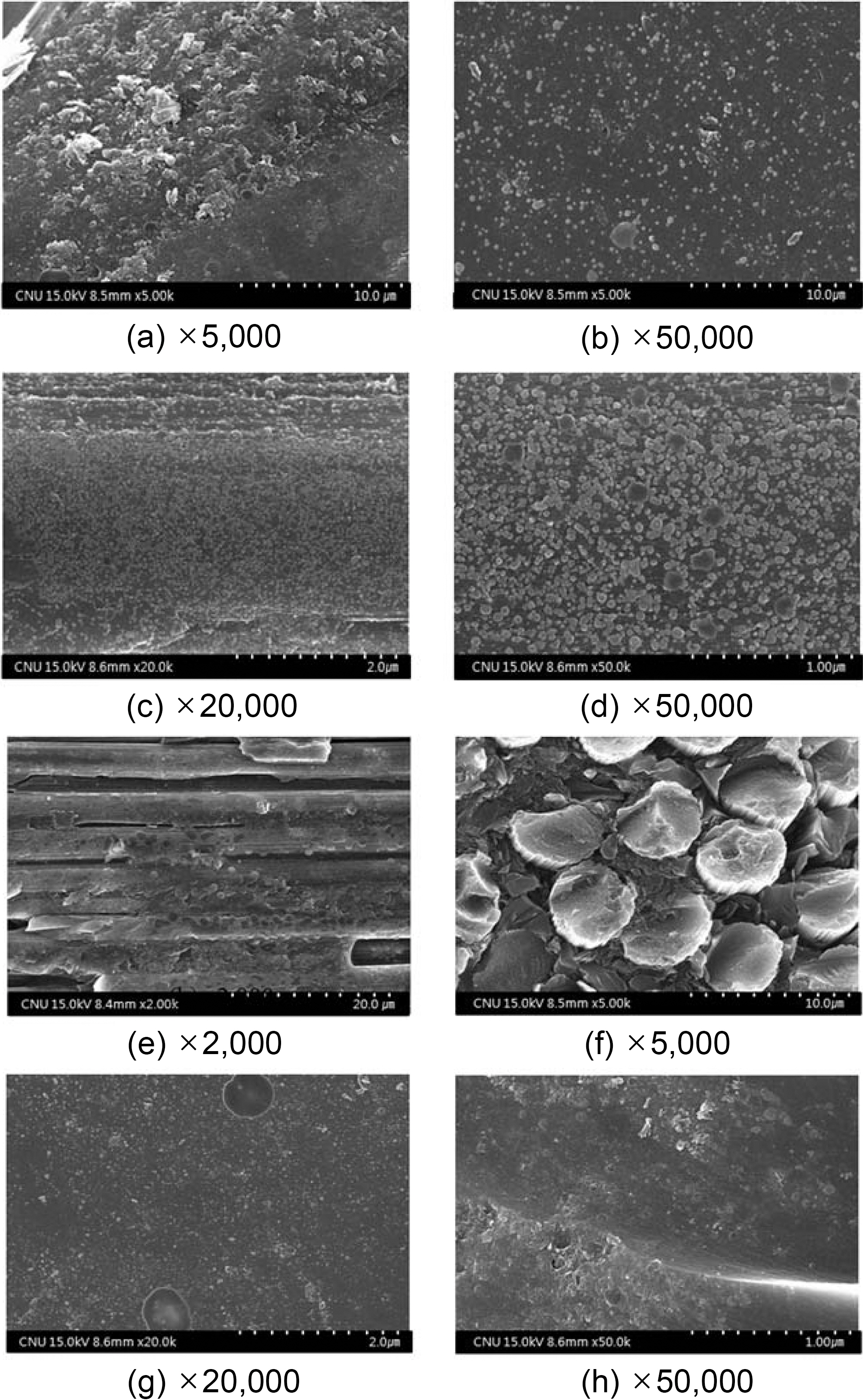
Fig. 4 shows the pressure-impregnation and carbonization based on HIP process No. 3 and the 420℃ dwell temperature of this cycle was maintained for 9 hours. In addition,regarding the atmosphere pressure, the point where 100 MPa of pressure was applied was 5 hours after the temperature reached 420℃. The figure also shows a picture of a specimen graphitized at 2800℃, as viewed through an electron microscope.
Fig. 4(a) shows the matrix within the matrix pocket of carbon/carbon composites. In this picture, no lamella shape of a graphite structure is found. Almost all structures are in spherical and consist of non-spherical grains, cluster of spherical grain, or a shape of combined spherical grains.
Fig. 4(b) is the enlarged version of the lower right section of Fig. 4(a), which seems amorphous. This section consists of very fine grains as well. These grains are in distributed sizes from 20~30 nm to 1 ㎛.
Fig. 4(c) shows the carbon matrix attached to the surface of the carbon fiber, and a number of grains are distributed on the surface of fiber. Fig. 4(d) is the same picture magnified 2.5 times. The grains are spherical, and a few grains demonstrating coalescence can be found in some areas.
The sizes of these spherical grains range from 30~50 nm to 150 nm. Comparing the pictures of Fig. 4 (a) to (d), the fine grains are more intensively formed on the carbon-fiber surface than within the carbon matrix.
This finding is due to the fact that the surface tensions within molten pitch are identical, although the molten pitch and the carbon fiber differ by being a liquid and a solid.
Accordingly, this phenomenon is thought to occur because the surface energy of the solid carbon fiber and the surface tension of the molten pitch greatly differ. In addition, oxide groups such as ?COOH, ?OH, ? O ? , ?CO exist on the surface of carbon fiber, and in particular, the carbon fiber used is PAN based carbon fiber that contains a large number of oxide groups. These functional group may have played a catalytic role in producing the mesophase nucleus.
The attractive strength of an oxide group is greater than that of the carbon, and thus, the molten pitch located around the fiber surface tends to collect the aromatic molecules towards the fiber surface. Furthermore, the flat aromatic molecules are forced to overlap to produce the mesophase nucleus.
Fig. 4(e)~(h) show different sections of an identical specimen. Fig. 4(e) shows the fiber bundle laid horizontally, and its fiber surface is covered with spherical particles that
are approximately size of 1 ㎛. Fig. 4(f) shows the cross section of the fiber bundle.
In this picture, a number of monofilament cross sections are shown, and they are surrounded by carbon matrixes. This specimen is processed with heat up to 2800℃ and thus, exhibits the typical graphite structure. However, no typical graphite structure can be found in the picture. Accordingly, it is estimated that degree of graphitization is low in this specimen.
In Fig. 4(g), tens of fine grains of nanometer size resemble the Milky Way Galaxy. In the upper and lower section of this picture, fine grains have grown considerably, and they form a microbead of an approximate size of 500 nm. In Fig. 4(h), fine spherical grains are distributed in approximate sizes of 1 ㎛.
The picture shows that these grains do not sit on top of the matrix but are instead partially buried in the matrix. These microbead are thought to develop into larger mesophase granular spheres under a conditions, in which the mesophase is produced by either extending the retention period or diminishing the atmosphere pressure.
Fig. 5 is a SEM photo of a specimen graphitized after demonstrating pressure impregnation and carbonization with HIP process No. 4.
Fig. 5(a) shows a matrix pocket, which consists of a number of grains. The grains range in size from a few hundred nanometers to micrometers and thus, it is assumed that the distributed grains are in different stages of growth.
Fig. 5(b) is the magnified version of the center section of Fig. 5(a). In this picture, some grains lie on the matrix surface but most of the grains are buried into the matrix. Accordingly, a large part of the matrix pocket consists of grains.
Fig. 5(c) shows a different matrix pocket of the same specimen. In this picture, a typical graphite structure is shown, and grains of approximately 100 nm are distributed on the surface. Based on these phenomena, it is clear that one specimen consists of diverse micro-structures. The grain sizes are diverse, but they consist of the typical graphite structures or amorphous matrixes.
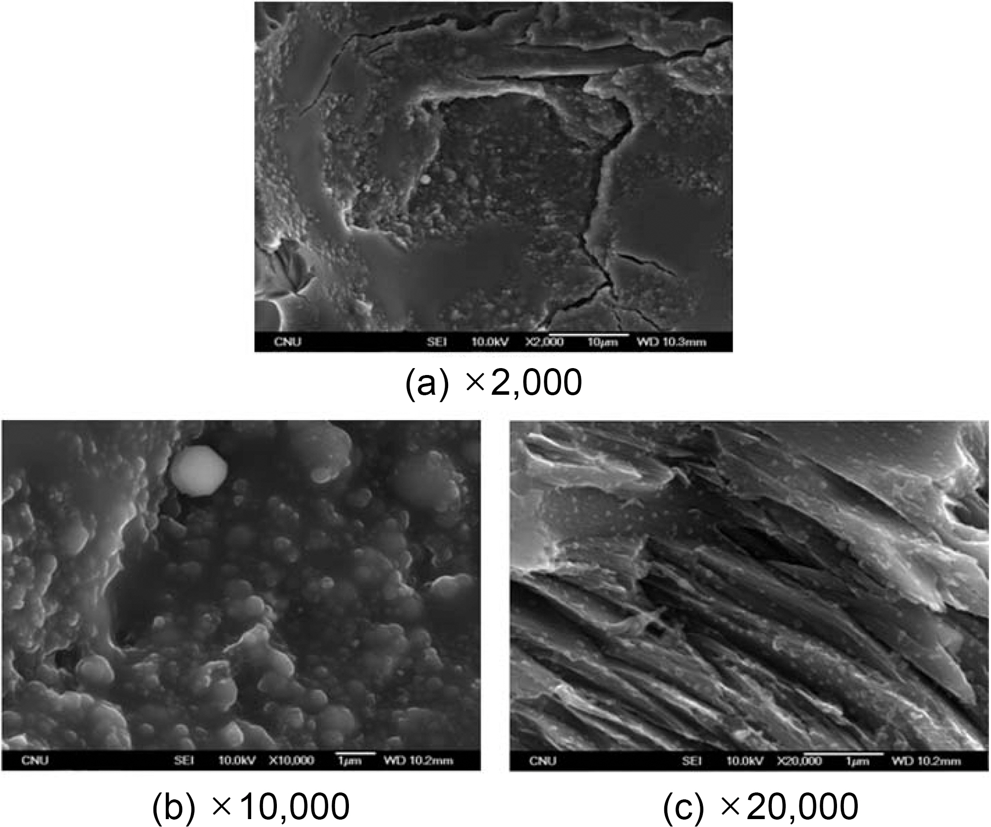
Fig. 6 is a SEM picture of a carbon mass graphitized at up to 2800℃ after pressure impregnation and carbonization HIP process No. 5. This carbon mass observed after graphitizing surrounds the carbon-fiber preform during the densification.
In all pictures, the spherical grains are exposed or buried under the matrix surface, and the grain sizes are approximately 100 nm. The carbon-fiber preform is weaved within a carbon/carbon composite, and the largest space is a matrix pocket. However, it still is a reasonably large space with approximate dimensions of 600 ×600 ×600 ㎛3.
However, an infinite space exists outside of the preform, when considered in the context of comparing the feasibility of a space effect when a grain structure is produced within the preform. As a result, there is no major difference between the aspects of the grain production within the preform and outside of the preform.
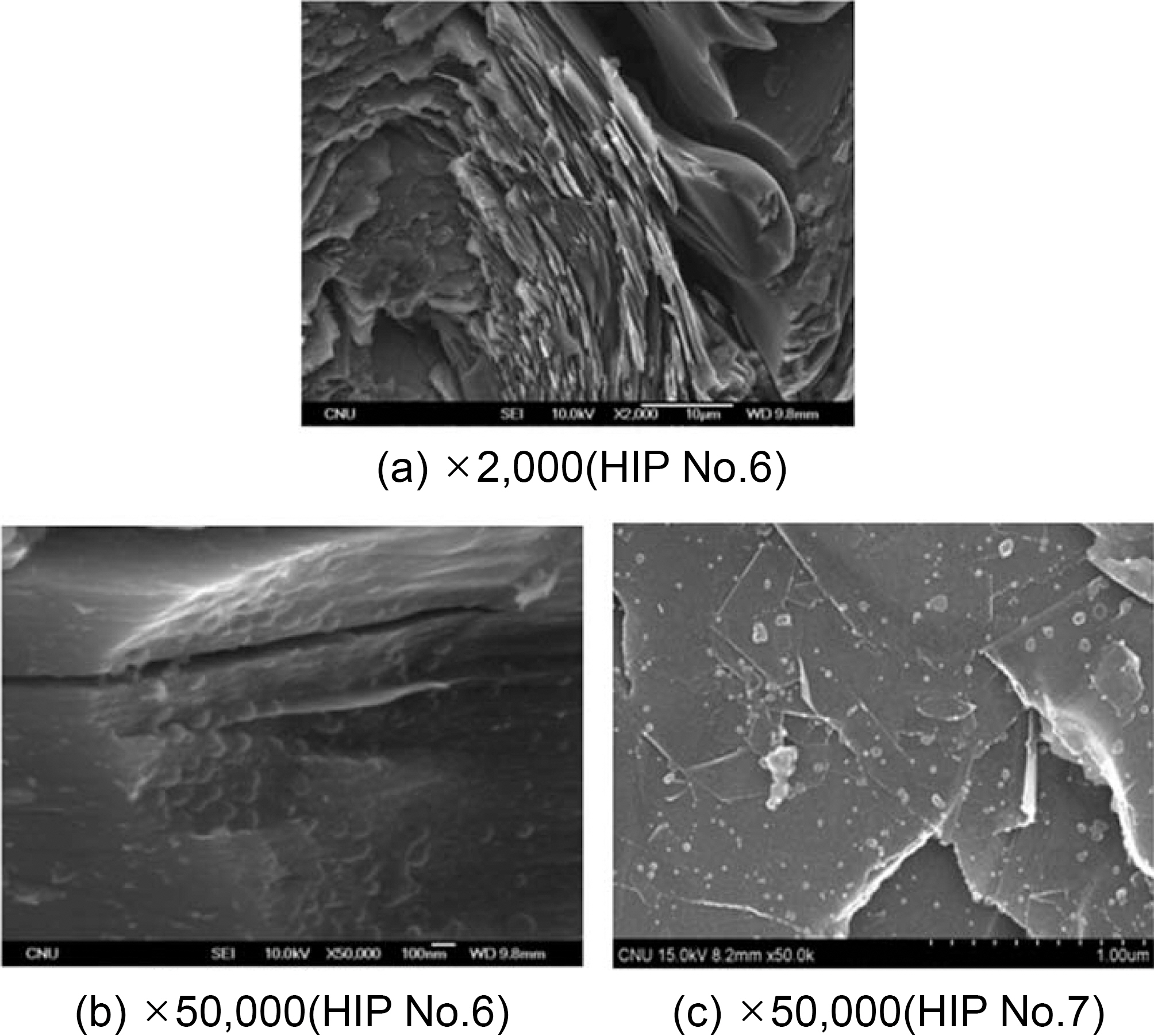
Fig. 7 shows a picture of a graphitized specimen containing relatively few spherical grains. Fig. 7 (a), (b) and (c) show pressure-carbonized specimens based on HIP processes No.6 and 7, respectively.
Fig. 7(a) shows a micro-structure frequently detected in the matrix of graphitized carbon/carbon composites. Namely, the lamella structure of graphite is overlapped in a number of layers, and the layers show signs of aromaticity. In the right-hand section of this picture, there is an amorphous
section that is different from the graphite section. Fig. 7(b) is the magnified version of this section. In this picture, the background structure seems amorphous. However, it is very slightly layered. Spherical grains of 50~100 nm sizes are distributed on the surface, and some are partially buried under the background matrixes.
Fig. 7(c) shows a considerably thin lamella structure, and granular spheres of the sizes of tens of nanometers are spread on the top.
To form the carbon matrix of a carbon/carbon composites into a fine grain structure, a research was performed by raising the pressure of pressure carbonization to 80 MPa and above, and by changing the temperature producing and enlarging a mesophase nucleus from 250℃ to 420℃. The high pressure of pressure-impregnation carbonization processing limits the fluidity of the melting pitch, thus restricting the mesophase nucleus growth, and, in turn, inhibiting the bulk mesophase transformation. As a result, a base of grain form was obtained. The formation of fine particles within the matrix, peaks at dwell temperatures between 350~420℃. The size of most of these particles was approximately 30 nm, and the particle size differed depending on the conditions, with some reaching between 100 nm and 1~2 ㎛. There were some irregular shapes among the spherical fine particles, which are most likely due to the partial coalescence of the spherical particles during the growth process. It is predicted that this phenomenon occurs as the viscosity of the melting pitch increases with increased system pressure. The formation of fine particles was larger on the surface of the fiber compared to in the matrix pocket. This phenomenon may be due to the fact that the free energy at the surface of the carbon fiber that contains oxide is larger than the surface tension of the melting pitch. The size of the particles within the matrix does not change significantly depending on the pressure differences of the system. However, the pressure differences did affect the size of the space in which the melting pitch was placed. As a result, the size of the particles formed in the matrix pocket of the preform was considerably smaller than that of the particles formed in the exterior of the preform.