The proliferation of electronics and instruments in commercial, industrial, healthcare, and defense sectors has led to a new kind of pollution known as electromagnetic interference (EMI). This is caused by the interference effects of current induced by electric and magnetic fields, emanating from nearby wide range of electrical circuitry [1]. It can also cause the human diseases such as leukemia, miscarriages, and breast cancer. So the investigation for the attenuation of EMI has been carried out more deeply by many researchers [2-7].
Metals are the most common materials for EMI shielding.But they suffered from the disadvantages like high density,susceptibility to corrosion, and uneconomic processing.Furthermore, metals reflect mainly the radiation and cannot be used in applications where absorption is the prime requisites such as in stealth technology [8]. Consequently,materials which can absorb the microwave effectively are needed for the improved EMI shielding efficiency (SE).
Carbon nanotubes (CNTs) became potential candidate for high-technology applications because of excellent electrical conductivity. CNTs may be used to shield the polymer matrix composites against EMI and the radio-frequency interference [9]. However, poor dispersion and lack of interfacial adhesion of CNTs give serious obstacles to their further development. To solve the above problems, various functionalization routes have been developed [10].
Conducting polymers are also used as materials for EMI shielding. Many reports have shown that the formation of conducting polymer/CNT composites can be considered as a useful approach for the fabrication of polymer-based devices [11-15]. Composites of conducting polymer and CNTs were prepared by in situ polymerization and intimate mixing [16]. Among these conducting polymers, polyaniline(PANI) attracts special interest due to its non-redox doping,good environmental stability, and economic feasibility. The properties of PANI can be further modified by controlling the polymerization conditions and using the substituted anilines, specific comonomers, dopants, and fillers [17-21].Polypyrrole (PPy) is also one of the most extensively studied conducting polymers. It shows high conductivity, oxygen resistance, thermal and environmental stabilities, relative ease of synthesis, and innoxious characteristics, which are favorable for the various applications [22].
In this study, we reported a simple procedure for the fabrication of PANI/multi-walled CNT (MWCNT) composites and PPy/MWCNT composites by in situ chemical oxidative template polymerization. This study aims to improve the overall EMI SE effectively by combining MWCNTs and conducting polymers. The conducting polymers were polymerized on the nano-sized carbon tubes rather than the micro-sized carbon filler or the nano-sized carbon black to improve the EMI SE more effectively in various frequency ranges. Both PANI/MWCNT and PPy/MWCNT composites have been investigated with respect to their morphology,permittivity, permeability, and EMI SE.
Aniline monomer (99%), pyrrole monomer (99%), ammonium persulfate (APS), and MWCNTs were purchased from Sigma Aldrich (USA). The diameter of MWCNTs is between 110 and 170 nm and purity of MWCNTs is higher than 90%. Sodium dodecyl sulfate as surfactant was obtained from ICN Biomedicals (USA). Hydrochloric acid(HCl) was obtained from Samchun Pure Chemical (Korea).Hydrogen peroxide (H2O2) was purchased from Kanto Chemical (Japan).
2.2. Synthesis of PANI/MWCNT composites and PPy/MWCNT composites
2.2.1. Pretreatment of MWCNT
The pristine MWCNTs were pretreated with H2SO4 at 80oC for 6 h. After being cooled to room temperature, the MWCNTs were washed with the distilled water followed by drying under vacuum at 60oC for 24 h, to give the carboxylfunctionalized MWCNTs [23].
2.2.2. Synthesis of PANI and PANI/MWCNT composites
The PANI was prepared by free radical chemical oxidative polymerization, through direct route using HCl as dopant. A 0.5 g of aniline monomer was dropped into distilled water and stirred continuously for 10 min. A 0.5 mL of HCl was added in the aniline solution as a dopant. A 0.5 g of APS dissolved in 10 mL distilled water was slowly added in the aniline solution and the solution was polymerized for 6 h at 0oC with constant mechanical stirring. The synthesized PANI was filtered and rinsed several times with the distilled water,methanol, and acetone, respectively. The PANI powder was dried under vacuum at 40oC for 24 h.
PANI/MWCNT composites were synthesized using in situ chemical oxidative polymerization on the MWCNT template.The polymerization of aniline was carried out in the distilled water using HCl as oxidant of aniline and APS as initiator. A 0.06 g of MWCNTs were dispersed in the surfactant solution and ultrasonicated over 1 h. A 0.5 g of aniline monomer was dropped into the MWCNT solution and stirred continuously for 10 min. Then 0.5 mL of HCl was added in the solution and 0.5 g of APS dissolved in 10 mL distilled water was slowly added in the solution. The polymerization was carried out for 6 h at 0oC with constant mechanical stirring. The synthesized PANI/MWCNT composites were filtered and rinsed several times with the distilled water, methanol, and acetone, respectively. The composite powders were dried under vacuum at 40oC for 24 h.
2.2.3. Synthesis of PPy and PPy/MWCNT composites
The PPy was prepared by free radical chemical oxidative polymerization, through direct route using H2O2 as oxidant.A 0.5 g of pyrrole monomer was dropped into distilled water and stirred continuously for 10 min. Then 0.2 mL of H2O2 was added in the pyrrole solution. A 0.5 g of APS dissolved in 10 mL distilled water was slowly added in the pyrrole solution and the solution was polymerized for 6 h at 0oC with constant mechanical stirring. The synthesized PPy was filtered and rinsed several times with the distilled water,methanol, and acetone, respectively. The PPy powder was dried under vacuum at 40oC for 24 h.
PPy/MWCNT composites were synthesized using in situ chemical oxidative polymerization on the MWCNT template.The polymerization of pyrrole was carried out in the distilled water using H2O2 as oxidant of pyrrole and APS as initiator.A 0.06 g of MWCNTs were dispersed in the surfactant solution and ultrasonicated over 1 h. A 0.5 g of pyrrole monomer was dropped into the MWCNT solution and stirred continuously for 10 min. Then 0.2 mL of H2O2 was added in the solution and 0.5 g of APS dissolved in 10 mL distilled water was slowly added in the solution. The polymerization was carried out for 6 h at 0oC with constant mechanical stirring. The synthesized PANI/MWCNT composites were filtered and rinsed several times with the distilled water, methanol, and acetone, respectively. The composite powders were dried under vacuum at 40oC for 24 h.
The morphology of the samples was characterized by field-emission scanning electron microscopy (FE-SEM) and field-emission transmission electron microscopy (FE-TEM).FE-SEM measurements were conducted at 15 kV using a Hitachi S-5500 (Hitachi, Japan). FE-TEM was performed on a JEM-2100F (JEOL, USA) at 200 kV. Permittivity, magnetic permeability, and EMI SE were obtained according to the ASTM D-4935-99 method using a network analyzer(E5071A, Agilent, USA) equipped with an amplifier and a scattering parameter (S-parameter) test set over a frequency range of 800 MHz-4 GHz. The EMI SE was calculated using S parameters.
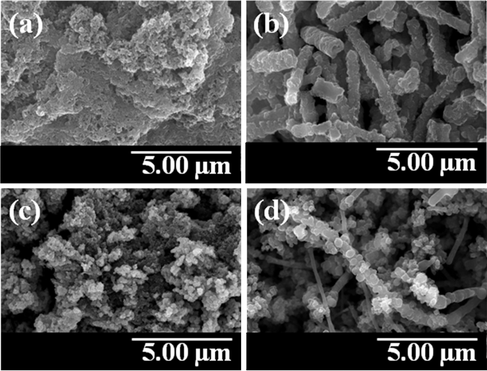
The FE-SEM images of PANI, PPy, and conducting polymer-coated MWCNTs were presented in Fig. 1. PANI was seen as bulk structure in Fig. 1(a). However, PANI was coated uniformly on the MWCNT templates as shown in
Fig. 1(b). The granular structure of PPy is shown in Fig.1(c). PPy was also coated onto the MWCNT surfaces with maintaining the granular structure as shown in Fig. 1(d).
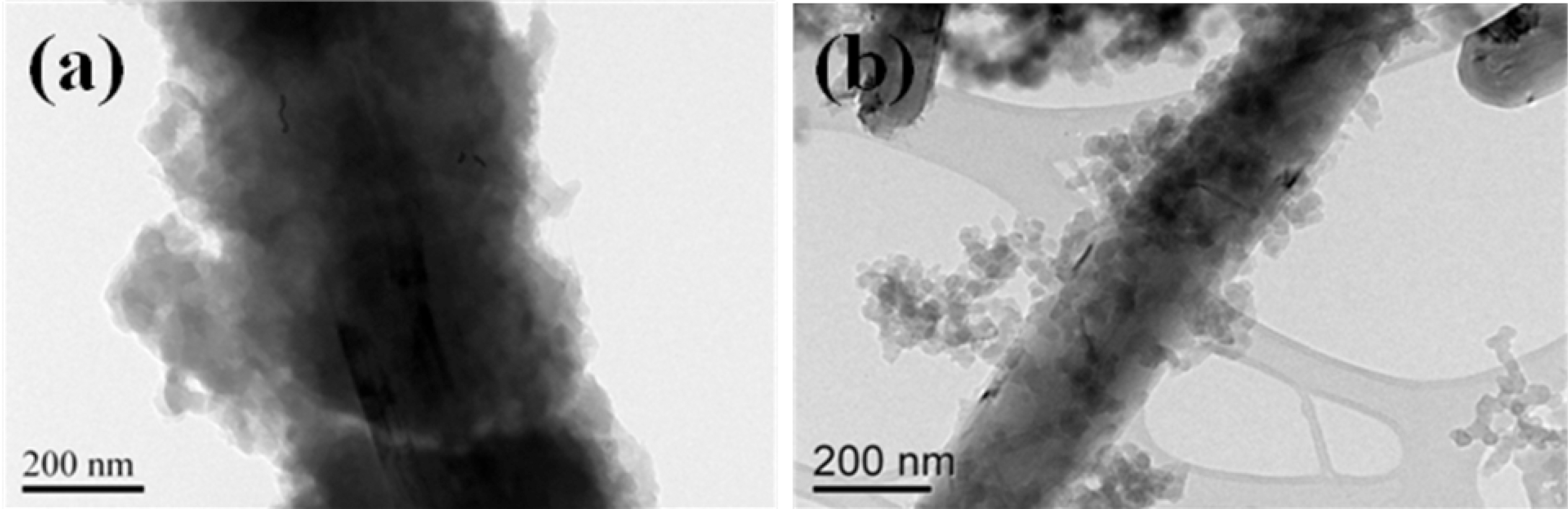
The uniform deposition of PANI and PPy on the MWCNT was confirmed by FE-TEM in Fig. 2. The bilayered structures of PANI-coated MWCNT and PPy-coated MWCNT were clearly observed and the coating of MWCNT with PANI and PPy was carried out successfully on the outer surface of MWCNT. These morphological chracteristics were expected to play an important role in applying the conducting polymer-coated MWCNT composites to the effective EMI shielding materials.
3.2. Permittivity and permeability
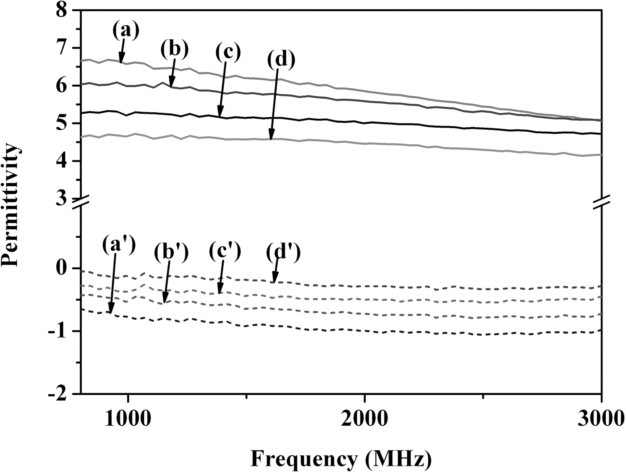
The permittivities of samples were illustrated in Fig. 3.
The real permittivity of conducting polymer-coated MWCNT was improved noticeably compared with those of PANI and PPy. The difference in the permittivity between conducting polymer-coated MWCNT and conducting polymer was attributed to the uniform coating of conductive PANI and PPy on the MWCNT resulting in the novel composite materials. The imaginary permittivity showed the similar trend as the real permittivity because the change of imaginary permittivity was strongly related to the change of real permittivity change.
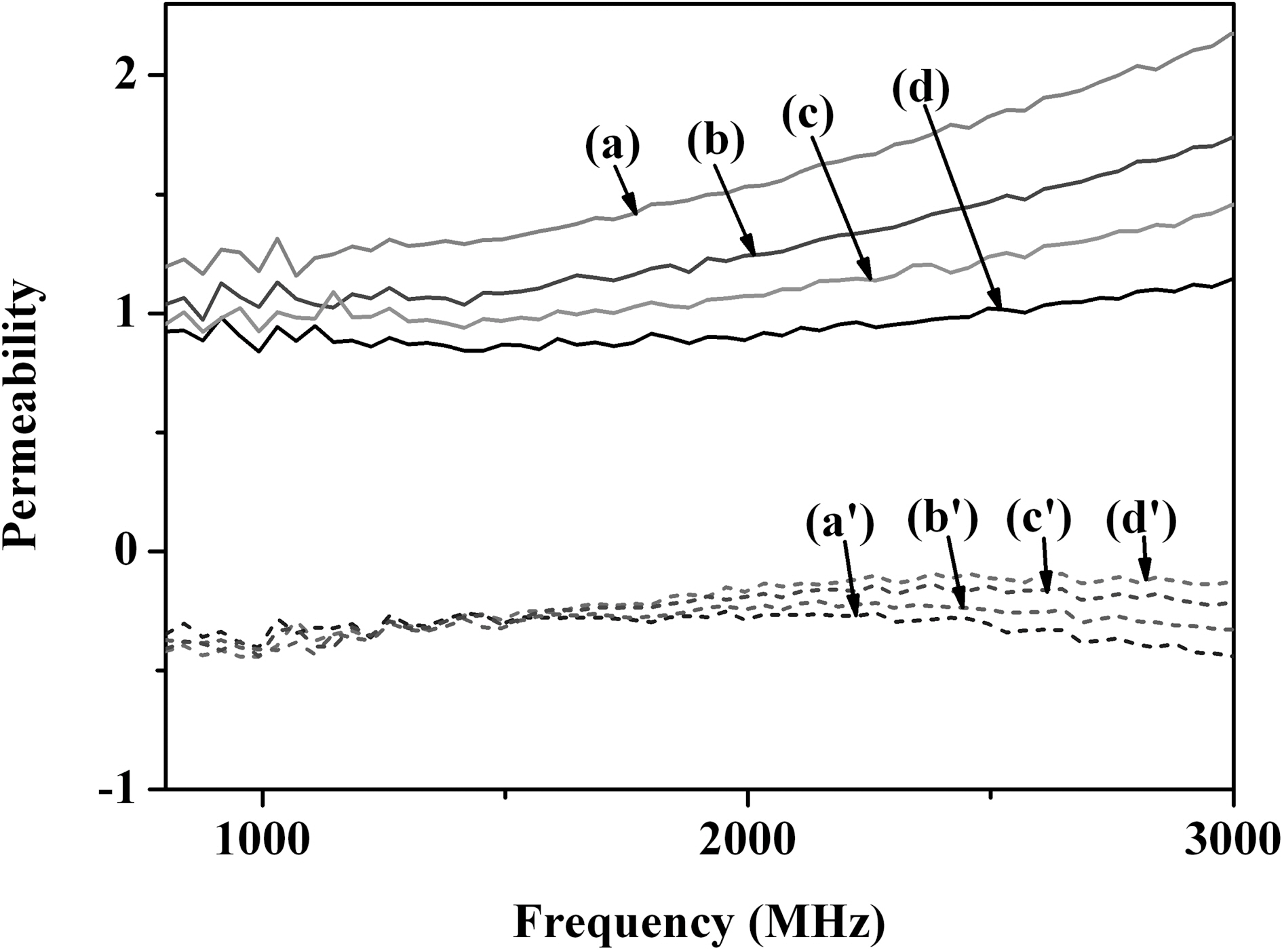
The permeabilities of PANI, PPy, and polymer-coated MWCNTs were shown in Fig. 4. The main trend was similar with that of permittivity behavior. The permeability was believed to increase significantly by improving the electrically conductive properties of composites effectively.
3.3. Electromagnetic interference shielding efficiency
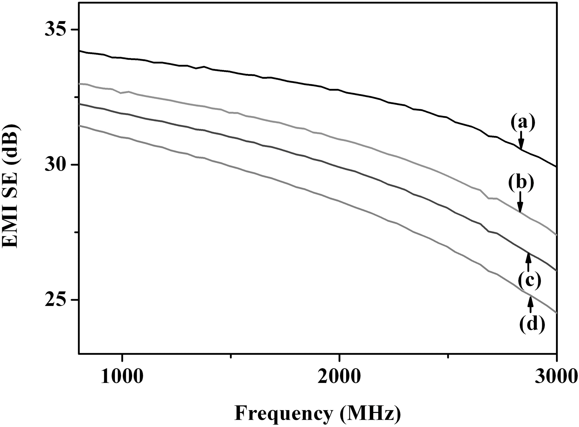
EMI SE is a number that quantifies the amount of attenuation of electromagnetic wave. The total EMI SE is defined as SE (dB) = log (PI/PT), where PT and PI are the power of transmitted and incident electromagnetic waves,respectively [24,25]. The EMI SE of the material depends on the thickness of the conductive coating and the content of conductive components [26].
Fig. 5 shows the EMI SE in the frequency range of 800-3000 MHz. The EMI SE of PANI/MWCNT composites and PPy/MWCNT composites was significantly improved compared with those of PANI and PPy. The difference in EMI SE between the conducting polymer-coated MWCNT and the conducting polymer was also attributed to the uniform coating of conducting polymer on the MWCNT resulting in the novel composite materials.
The composites of conducting polymers and MWCNT were prepared by template polymerization on the surface of MWCNTs for the effective EMI shielding materials. The PANI and PPy formed uniformly on the surface of MWCNTs were confirmed by FE-SEM and FE-TEM. The permittivity, permeability, and EMI SE were improved significantly by coating the conducting polymer on MWCNTs. Conducting polymer-coated MWCNT showed the synergistic effects in improving the EMI shielding properties based on the combination of electrical properties of MWCNTs and conducting properties of PANI and PPy.