The rapid development of information technology integrated with wireless communication demands miniaturization processes, high-speed technology, and multi-function systems for the complex communication devices in the market today [1,2]. The demands for miniaturization and weight reduction requires specific functions of an electronic circuit to be consolidated to a single module, necessitating the use of low temperature co-fired ceramic technology (LTCC). A zero-shrinkage sintering process is an imperative aspect in LTCC necessary for reducing dimensional uncertainty in the ceramic substrate during the firing process and improving the matching precision between the ceramic layers [3,4].
Three methods for a zero-shrinkage sintering process have been researched and proposed including pressure assisted sintering(PAS) [5] and self-constrained sintering (SCS) [6,7]. However,many problems exist with these methods when applying them to mass productions of products. This current study suggests the glass infiltration method in order to alleviate the issues encountered with PAS and SCS [8]. The glass infiltration method proposed here also includes the structure of Al2O3/glass/ Al2O3. However, additional problems are encountered with the glass infiltration method, including partially incomplete joining between Al2O3 and glass layers during the sintering process [4].
In this study we investigated why delamination occurred at the Al2O3/glass interface [9]. Then, we suggested a mechanism and solutions for the delamination.
In this study, we developed starting materials with commercial raw powders such as Al2O3 (particle size of 0.5 ㎛, AES-11; Sumitomo Co., Japan) and Pb-B-Ti-Si-O glass (particle size of 2.53 ㎛, sud1130; Phoenix PDE, Korea). In addition, we fabricated a Pb-B-Si-O glass without TiO2 synthesized by quenching a Pb-B-Si-O glass omitting TiO2 melted in the Pt crucible at 1,300℃.
The slurry of the glass and Al2O3 with 800-1,000 cPs was made by mixing toluene and ethanol with glass and Al2O3 powders for
24 hours. This mixture was then again mixed with PVB binder and plasticizer. Subsequently, the slurry was cast to thicknesses of 7 ㎛ and 10 ㎛ through a doctor blade method.
The process of the zero-shrinkage LTCC layer comprises the composition of a 15 × 15 mm Al2O3/glass/Al2O3 bundle using a lamination press after warm isostatic press (WIP) treatment. The sample was then sintered with a rising rate of 1℃/min to 900℃ for 20 minutes and then slow cooled in the furnace.
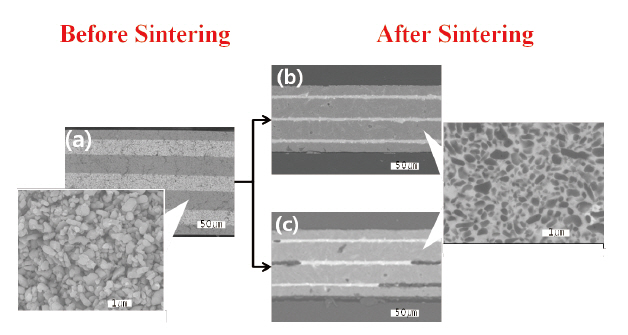
Figure 1 shows the glass infiltration substrate using Pb-glass. Fig. 1 (a) displays the green sheet of the Al2O3/glass/Al2O3 bundle. Figs. 1 (b) and (c) display the substrate after sintering at 900℃. Furthermore, Fig. 1 (a) shows an Al2O3 powder; Figs. 1(b) and (c) show densified Al2O3 infiltrated by glass. Fig. 1(b) it shows the microstructure of the glass layer of which the thickness remained within the range of 3-5 ㎛ after infiltration. However, a space exists across the glass layer after infiltration, as shown in Fig. 1 (c). The phenomena expressed through Figs. 1 (a)-(c) appeared at nonuniform regions with partially remained glass due to insufficient glass content in the system. In particular, for a large LTCC layer made by the zero-shrinkage sintering process, these nonuniform regions may increase the loss of dielectric properties and decrease the reliability to various electrical loads. Also if the contents of the glass are not sufficient for infiltration, de-lamination to the layers between the glass and Al2O3 must occur [4].
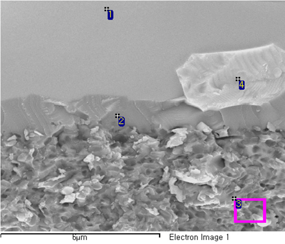
Figure 2 shows the scanning electron microscope (SEM) im-
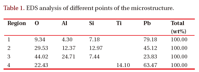
[Table 1.] EDS analysis of different points of the microstructure.

EDS analysis of different points of the microstructure.
age at the glass/Al2O3 interface. There were 4 phases in the glass layer using SEM in comparison to Fig. 1 (b). The EDS results are shown in Table 1. Region 1 exhibits the glass composition. Region 2 shows a different component ratio of glass vs. the Al2O3 phase. For Region 3, in which the glass infiltration was somewhat completed, the component ratio of glass and the Al2O3 phase also differed in comparison to Regions 1 and 2. However, Region 4 shows the Ti-Pb-O precipitate as a bright particle including a Ti component that did not appear in the other regions.
We conducted experiments in order to examine the effects of Ti-rich bright particles during glass infiltration. During the experiments, an Al2O3/glass/Al2O3 bundle was fabricated and controlled.However, the bundle did not possess residual glass.
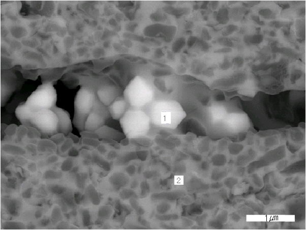
Figure 3 shows the microstructure of a bright particle in the glass region. The glass infiltrated toward the Al2O3 layer; however, bright particles remained, creating a large pore in the glass layer. This large pore prevented the layers from joining to each other. The bright particles were attributed to de-lamination.
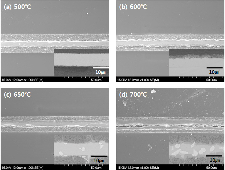
Figure 4 shows that the bright particles do not appear in the samples of Al2O3/glass/Al2O3 structure at (a) 500℃, (b) 600℃,but appears at (c) 650℃, and observed more at (d) 700℃. In Fig.4, the Ti-Pb-O phases were precipitated at the interface at 650℃ and the contents of these increased with increasing sintering temperature, and remained at the interface of the Al2O3/glass at 700℃ with glass phase that did not infiltrate toward Al2O3 layer. The Ti-Pb-O phases were thought to have formed column-like shapes due to the mobility of glass, which provided sufficient movement of these columns during the glass infiltration process. As sintering proceeds, glass particles melt and infiltrate into Al2O3 layer. Some glass reacts with Al2O3 and other glass infiltrates continuously. And as temperature increases, more and more glass infiltrates toward exterior part of Al2O3 layer, and Ti particles merges to make Ti-Pb-O phases which is thought to hinder infiltrates toward Al2O3 layer. Ti-Pb-O phases remains at the interface, causing de-lamination in the system.
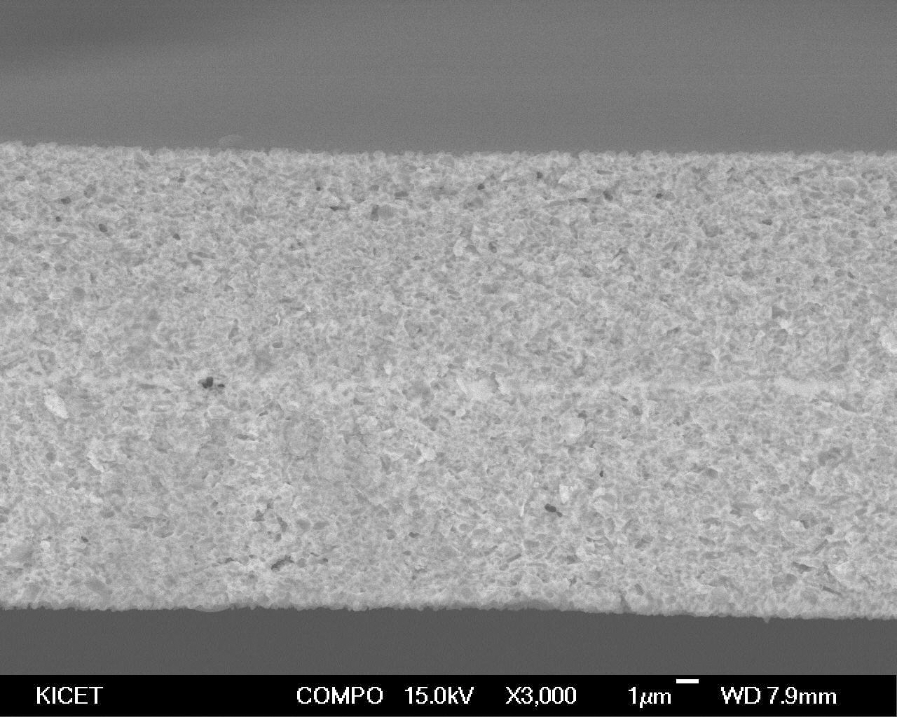
From previous results, in order to diminish the de-lamination phenomena, we synthesized Pb-B-Si-O glass without TiO2 at the Pb-B-Ti-Si-O glass and laminated the green sheets of each 7 ㎛ Al2O3 and 10 ㎛ glass to Al2O3/Glass/ Al2O3 layers. Then, we conducted the same process. Figure 5 shows the microstructure of a single bundle substrate using Pb-B-Si glass. As displayed in Fig.5, no Ti-Pb-O phases existed at the interface of Al2O3/glass even though glass did not remain at the interface. Therefore, the delamination phenomena disappeared. In addition, a dense zeroshrinkage LTCC layer was fabricated without any special defects. The layer properties were 0.15% of x-y axis shrinkage, 41% of z-axis shrinkage and 3.93 g/cm3 of density.
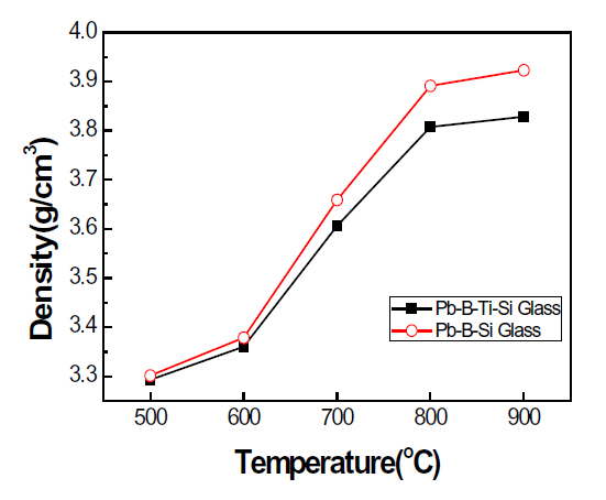
Figure 6 shows the densities of zero-shrinkage layers with sintering temperature for the Pb-B-Ti-Si-O glass and Pb-B-Si-O glass. The density of the Pb-B-Si-O glass system was higher than that of Pb-B-Ti-Si-O glass system at a temperature of 600℃. At 600℃, glass infiltration occurred and the difference of density between the systems increased with increasing sintering temperature. This suggests that the difference of density is caused by the partial delamination of Pb-B-Ti-Si-O glass induced by the Ti-Pb-O phase in Figs. 4(c) and (d). At 900℃, the density difference of Pb-B-Ti-Si-O and Pb-B-Si-O glass system was 0.11 g/cm3 as 3.93 g/cm3 and 3.82 g/cm3, respectively.
In this study, we introduced a glass infiltration method. This glass infiltration method is a zero-shrinkage sintering process for an LTCC layer composed of Al2O3/glass. For the Pb-B-Ti-Si-O glass composition, the precipitate of the Ti-Pb-O phase appeared at 650℃ in firing. Additionally, de-lamination between Al2O3 and glass layer appeared because the Ti-Pb-O phase in the columnlike shape still existed at the interface of Al2O3/glass in which a glass phase did not exist due to the infiltration of glass toward the Al2O3 layers. From this mechanism, we developed green sheets using the Pb-B-Si-O glass without TiO2 in Pb-B-Ti-Si-O glass and laminated these to Al2O3/glass/Al2O3 structure and then sintered to manipulate the zero-shrinkage LTCC layers with 0.15% of x-y axis shrinkage, 41% of z-axis shrinkage and 3.93 g/cm3 of density without any special defects.