Due to their outstanding chemical and thermal stabilities and electrical insulating properties, polychlorinated biphenyls (PCBs) have been used for a wide variety of applications, including dielectric fluid in transformers and capacitors, sealants and plastics [1, 2]. However, since the widespread environmental contamination by PCBs was confirmed in the late 1960s (Kanemi Yusho accident in 1968), their production and use has began to be prohibited or restricted in the USA and Western Europe since the late 1970s[3-5]. In the case of Japan, both the production and use of PCBs were banned in 1972[3]. In Korea, the commercial use of PCBs were limited in 1979, and subsequently banned in 1996[6]. However, PCBs were considered commercially valuable and produced in large quantities from 1929 to 1976[7];thus, they still remained in insulating oils for transformers and capacitors that were in used prior to the regulations being imposed. The widespread release of PCBs into the environment has presented a serious problem due to their persistence and toxicity. The toxic effects are compounded by their hydrophobicity,which causes PCBs to bio-accumulate in the fatty tissues of animals [8]. Additionally, PCBs possess high thermal and chemical stabilities and are not easily decomposed or biodegraded in natural systems [9]. These are main reason adequate monitoring and treatment plans for PCBs are important. According to the Stockholm Convention on Persistent Organic Pollutants(POPs), which came into force in May 2004, many countries were required to eliminate the use of PCBs in equipment (e.g.,transformers, capacitors or other receptacles containing liquid stocks) by 2025, and were subject to review by the conference of the parties. Until recently, some of conventional methods, such as the dimethyl sulfoxide (DMSO) partition method and alkali digestion method, were used for the analysis of PCBs in insulating oils. However, these methods required much analytical time, use of solvents and manual sample manipulation, which can potentially give rise to decreases in precision and accuracy,as well as the risk of human exposure. Furthermore, there are some problems associated with extracting and purifying PCBs in insulating oils, as they contain many aromatic compounds and have high viscosity [10, 11]. Especially, Japan has planned to eliminate PCBs by 2016, and many research groups, with the Ministry of Environment as a counter, have led the development of new methods that can cut the costs and reduce analysis time of the PCBs in insulating oils [12]. As a result, our laboratory has developed a new rapid analytical method (heating of the multilayer silica gel column/alumina column method) for the analy-
sis of PCBs in insulating oils. Some reports have indicated that increasing the temperature of a multi-layer silica gel column can give better purification effects than of the same column at room temperature [12-14]. It has also been reported that the solvent usage can be reduced as a result of the higher solubility of PCBs in a heated solvent [15, 16]. This new rapid analytical method could remove almost all the material that can interfere, such as aromatic hydrocarbon and paraffin, etc. Furthermore, the entire pretreatment procedure can be completed within 2 hr, with about only 20 mL of solvent. According to the Stockholm Convention,the elimination of the use of PCBs in equipment has become a global problem. Therefore, a new rapid analysis method has been introduced, which it is hoped could be used as the reference method in many countries with the need to develop rapid analytical methods. Because Korea has tried to eliminate the use of PCBs by 2015, the development of a new rapid analysis method for the PCBs in insulating oils has become inevitable. Thus, this study initially investigated the possibility of the application our new rapid analytical method in Korea.
KC-Mix solution (with KC-300, KC-400, KC-500, and KC-600 mixed at a 1:1:1:1 mass ratio; GL Science Inc., Tokyo, Japan) was used as the PCBs standard solution. The KC-Mix solution was diluted by the addition of toluene to make a 100 ng/mL solution,which was used for calibration. 2, 3, 3’, 4, 4’, 5, 5’-H7CB (IUPAC No. 189), as a PCB standard product (CIL PCB-189; Cambridge Isotope Laboratories Inc., Andover, MS, USA), was used as a cleanup spike, with 2, 2’, 3, 3’, 4, 4’, 5, 5’, 6, 6’-D10CB (IUPAC No. 209), another PCB standard product (CIL PCB-209; Cambridge Isotope Laboratories Inc.), was used as a syringe spike.Each standard solution was diluted by the addition of isooctane to make a 100 ng/mL solution.
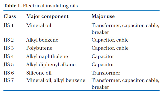
Insulating oil samples were made by spiking 75 ng of a PCB standard solution into 0.1 g of PCB-free insulating oils (JIS 1 to JIS 7). These oil samples were used in recovery rates and reproducibility experiments. The characteristics of each insulating oil are presented in Table 1.
2.3. Multi-layer Silica Gel Column/Alumina Column
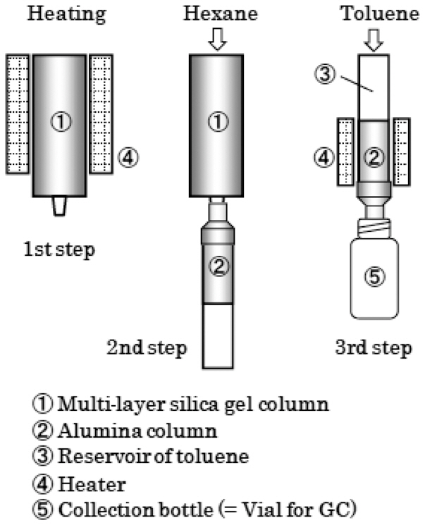
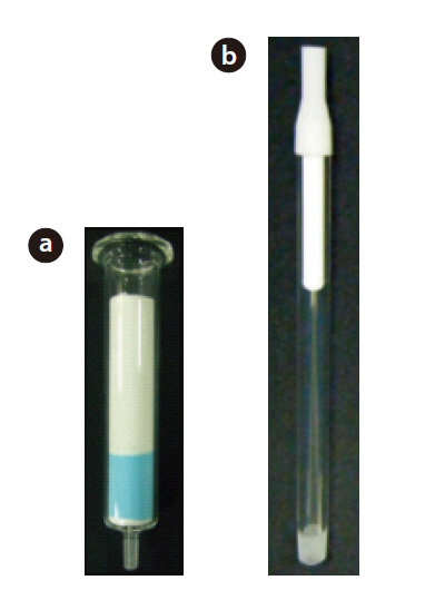
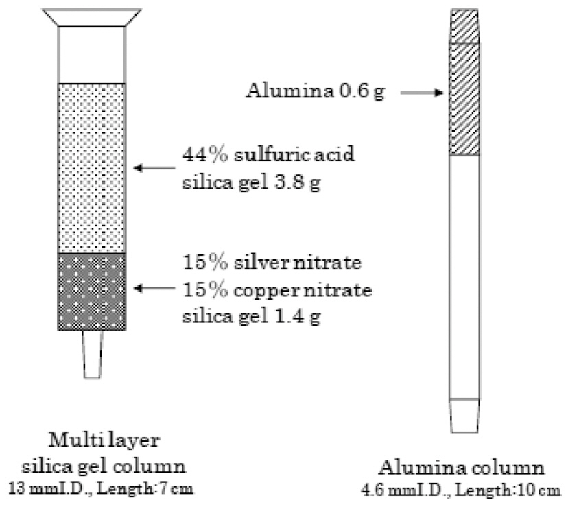
The multi-layer silica gel column/alumina column set used in this study is shown in Fig. 1, with a schematic view shown in Fig. 2. The multi-layer silica gel column was filled with 1.4 g of silica gel impregnated with silver nitrate (15% mass fraction) and copper nitrate (15% mass fraction) at the bottom, with 3.8 g of silica gel impregnated with sulfuric acid (44% mass fraction) at the upper of the column. The alumina column was filled with 0.6 g of activated alumina. The schematic diagram of the 3 step operation for the column set is shown in Fig. 3.
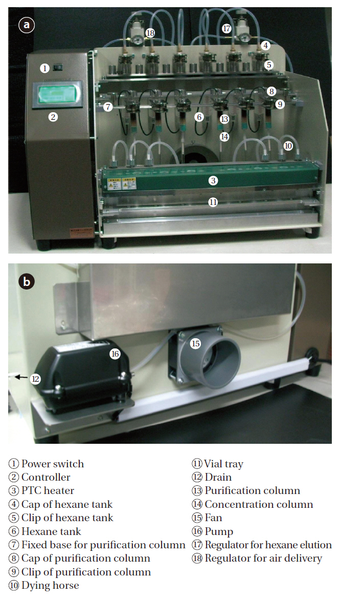
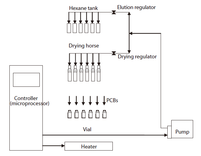
The name of each part of the pretreatment device is shown in Fig. 4, with the schematic diagram of the control system shown Fig. 5. The pretreatment device consisted of a controller, a column tray, a heater, pressure control valves and a pump. Dry tubes were made of silicon, and elution tubes of polyurethane,with connectors made of Teflon. The operation was performed using a manipulation touch panel.
[Table 1.] Electrical insulating oils

Electrical insulating oils
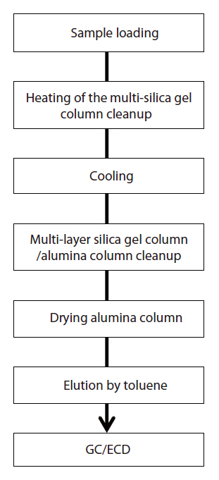
The schematic diagram of the PCBs analytical using the rapid analysis method is shown in Fig. 6. A 0.1 g insulating oil sample was placed in a micro vial, with a 20 μL cleanup spike (2 ng of IUPAC No. 189) then added to the sample. After the sample had been applied onto the multi-layer silica gel column, it followed by the setting on the heater which preheated by 85℃. Then, the multi-layer silica gel column was heated on the heater for 1 hour. After the multi-layer silica gel column had cooled by 40℃, the PCBs were eluted with 20 mL of hexane, and then trapped in the alumina column. The alumina column was separated from the multi-layer silica gel column, and reversibly set on the heater, which was maintained at 85℃. The alumina column was then dried on the heater, while passing fresh air or nitrogen gas. The PCBs were eluted with approximately 250 μL of toluene by the addition of 600 μL of toluene onto the alumina column.The syringe spike (2 ng of IUPAC No. 209) was then added to the toluene eluted solution. The entire pretreatment procedure was completed in about 2 hr using the pretreatment device and multi-layer silica gel/alumina column set.
The identification and quantification of the PCBs in insulating oils were carried out using GC/ECD (7890 GC/ECD; Agilent Technologies, Santa Clara, CA, USA). The GC capillary column used in this study was a DB-5 (30 m i.d, × 0.25 mm, df = 0.25 ㎛;J&W Scientific, Folsom, CA, USA). The scan measurement was carried out using GC/QMS (JMS-Q 1000GC; JEOL, Tokyo, Japan), with the same GC capillary column. The measuring conditions during the GC/ECD and GC/QMS are shown in Table 2.
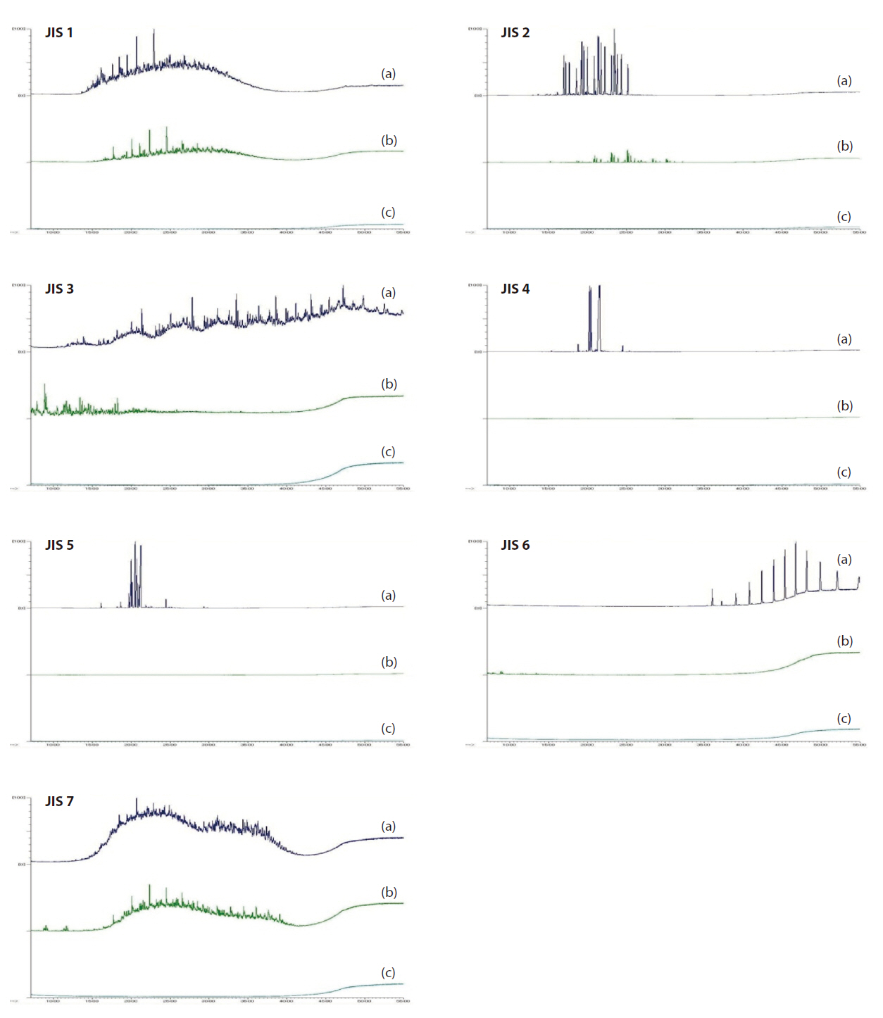
The sample solutions of the insulating oils for the scan measurements by GC/QMS were diluted by the addition of hexane to make 500 mg/L solutions. The total ion current (TIC) is shown in Fig. 7, where 7(a) represented the TIC of the sample solutions before purification, (b) the TIC of the hexane solutions after pu-
[Table 2.] Instrument conditions for the measurements
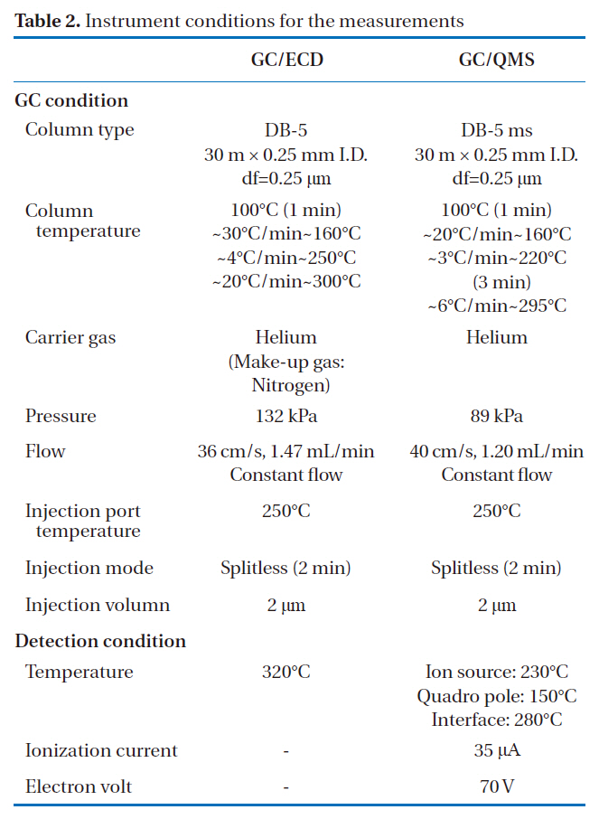
Instrument conditions for the measurements
rification via the multi-layer silica gel column, and (c) the TIC of the toluene solutions after purification via the multi-layer silica gel column and alumina column. Cases of JIS 1 and JIS 7 in Fig.7 showed that the peaks in the TIC had decreased after purification via the multi-layer silica gel column (b). The reason for this was that the aromatic hydrocarbons in JIS 1 and JIS 7 were absorbed into the solid phase via sulfonization by the sulfuric acid.The residue peaks in TIC (b) for JIS 1 were assumed to be the paraffin that had not reacted with the sulfuric acid or absorbed into the silver and copper impregnate silica gel. Thus, the reason no peaks were observed in TIC (c) for JIS 1 was that the paraffin was separately purified by the alumina column. In the case of JIS 6 in Fig. 7, almost all the peaks were removed after purification via the multi-layer silica gel column (b). It was assume that the polysiloxane bonds were polymerized or decomposed by the heated sulfuric acid. In the cases of JIS 2, JIS 4, and JIS 5 in Fig. 7, almost all the peaks were decreased or removed after purification via the multi-layer silica gel column (b). The reason for this was that the aromatic hydrocarbons, which were the main components of JIS 2, JIS 4, and JIS 5, were absorbed into the solid phase via sulfonization by sulfuric acid. In the case of JIS 3 in Fig. 7, almost all the peaks were decreased or removed after purification via the multi-layer silica gel column and alumina column (c). However, some of the peaks appeared in (b), but not in (a). It could be assumed that the reaction products of polybutene were generated by heating of the multi-layer silica gel column. However, these reaction products were separately purified by the alumina column. The above results indicate that the main components of JIS 1, JIS 2, JIS 3, and JIS 7 were separately purified by heating of the multi-layer silica gel column and alumina column; whereas, the main components of JIS 4, JIS5, and JIS 6 were purified by heating of the multi-layer silica gel column.
3.2. Recovery Rates and Reproducibility
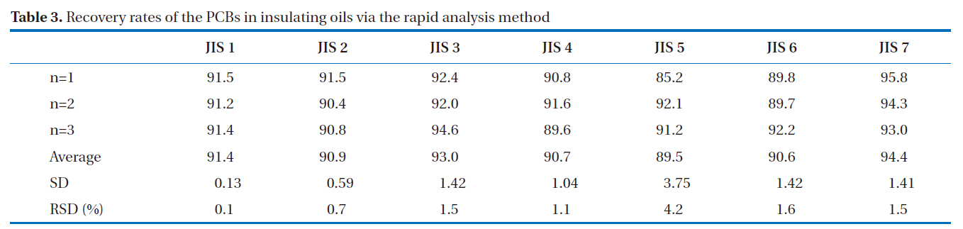
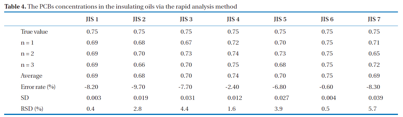
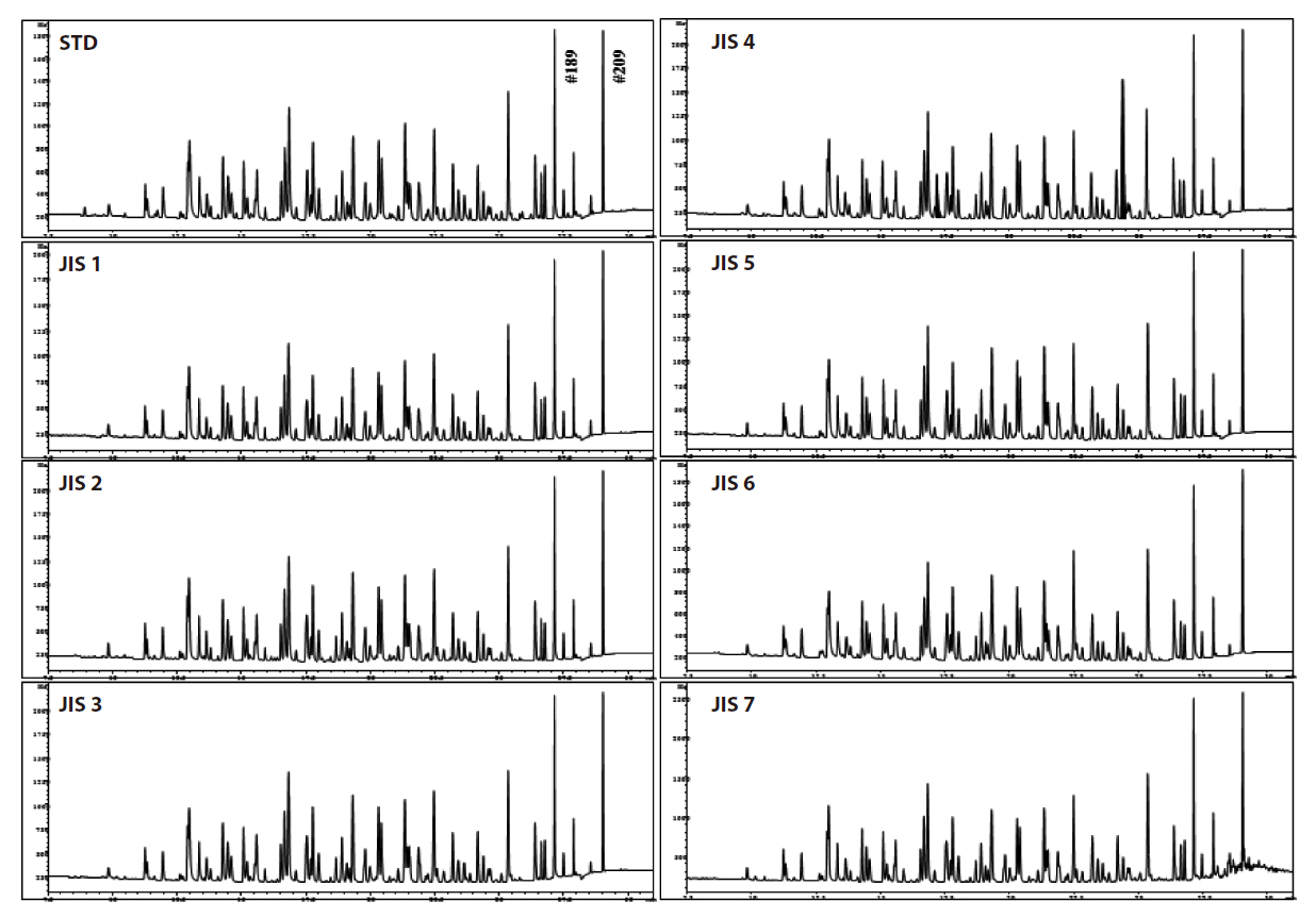
GC/ECD was used for the recovery rates and reproducibility experiments. The GC/ECD chromatograms after the pretreatment stage of the rapid analysis for the PCBs in insulating oils are shown in Fig. 8. There were no interference peaks in the chromatograms; thus, exact quantification was realized. The recovery rates of the samples spiked with 2, 3, 3’, 4, 4’, 5, 5’-H7CB (IUPAC No. 189) were within the allowable range of 75-120%; all were greater than 89%, as shown in Table 3, with relative standard deviations below 6.0%, as shown in Table 4, indicating the highly stable reproducibility of the rapid analysis method (heating of the multi-layer silica gel column/alumina column). The reason for the high PCB recovery rates was that the heating of the multi-layer silica gel column/alumina column was a highly efficient adsorption and desorption process for the elution of PCBs using different solvents. The main reason for the high reproducibility was that this method was simplified and semiautomated by the pretreatment device.
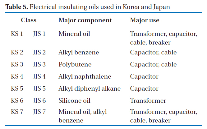
The possibility for the application of this rapid analysis method to other countries was also investigated. Korea has a plan to eliminate PCBs by 2015, and has previously used the alkali digestion method as its official method. The characteristics of the insulating oils used in Korea and Japan are shown in Table 5, which shows that KCs 1 to 7 are identical to JISs 1 to 7. In addition,Kanechlor (KC-300, KC-400, KC-500, and KC-600) can be
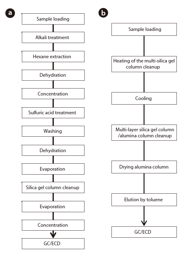
used as a substitute for Aroclor standard products (Aro-1242,Aro-1248, Aro-1254, Aro-1260) [17]. As a result, it was confirmed that this rapid analysis method can be effectively used in Korea. The schematic diagrams of the alkali digestion and rapid analysis methods are shown in Fig. 9. In Fig. 9(a), the pretreatment procedure of the Korean official method [17] was performed, as follows: alkali treatment, liquid-liquid extraction, sulfuric acid treatment and silica gel column cleanup, which took over 20 hours to complete. In Fig. 9(b), the pretreatment procedure for the rapid analysis method was performed, as follows: heating and cooling multi-layer silica gel column and multi-layer silica gel column/alumina column cleanup, which took about only 20 hours to complete. The analytical comparison of the two methods is shown in Table 6. The rapid analysis method, with the pretreatment device, could reduce the pretreatment time and solvent usage by 1/10 and 1/25 to 1/50, respectively.
[Table 3.] Recovery rates of the PCBs in insulating oils via the rapid analysis method

Recovery rates of the PCBs in insulating oils via the rapid analysis method
[Table 4.] The PCBs concentrations in the insulating oils via the rapid analysis method

The PCBs concentrations in the insulating oils via the rapid analysis method
[Fig. 9.] Analytical procedure for the official Korean method (a) and the rapid analysis method (b).

[Table 5.] Electrical insulating oils used in Korea and Japan

Electrical insulating oils used in Korea and Japan
[Table 6.] Analytical comparison between the official Korean method and the rapid analysis method
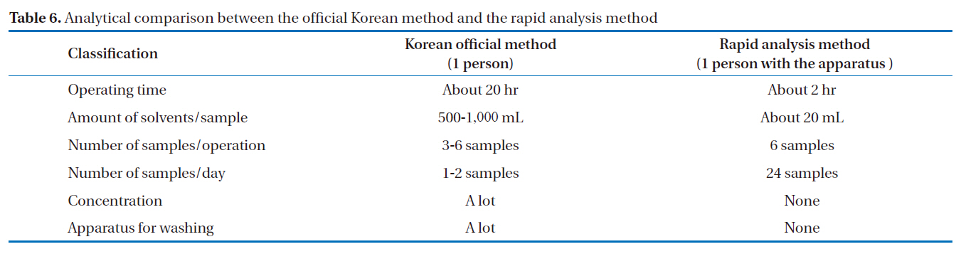
Analytical comparison between the official Korean method and the rapid analysis method
We have introduced a new rapid analysis method (heating of the multi-layer silica gel column/alumina column), which was shown to possess a high purification ability, high recovery rate and good reproducibility. Furthermore, this high purification ability could help with anti-aging of the GC column and detector. The pretreatment procedure was always able to be uniformly performed, regardless of type of insulating oils. This simplified and semi-automated analytical method using the pretreatment device could reduce the experiment errors, training time for the analyst and increase the accuracy of the experiment, and also reduce the required sample manipulation; therefore, leading to decreased risks of human exposure. Finally, this rapid analytical method could reduce the pretreatment time and solvent usage by 1/10 and 1/25 to 1/50, respectively, and increase the number of pretreated samples analyzed per day by 12 to 24 times compared to the official Korean method. Thus, it could reduce the analysis time and costs compared to the official Korean method.