To prepare for a Korean lunar orbiter mission, a precise lunar orbit propagator; Yonsei precise lunar orbit propagator (YSPLOP) is developed. In the propagator, accelerations due to the Moon’s non-spherical gravity, the point masses of the Earth, Moon, Sun, Mars, Jupiter and also, solar radiation pressures can be included. The developed propagator’s performance is validated and propagation errors between YSPOLP and STK/Astrogator are found to have about maximum 4-m, in along-track direction during 30 days (Earth’s time) of propagation. Also, it is found that the lifetime of a lunar polar orbiter is strongly affected by the different degrees and orders of the lunar gravity model, by a third body’s gravitational attractions (especially the Earth), and by the different orbital inclinations. The reliable lifetime of circular lunar polar orbiter at about 100 km altitude is estimated to have about 160 days (Earth’s time). However, to estimate the reasonable lifetime of circular lunar polar orbiter at about 100 km altitude, it is strongly recommended to consider at least 50 × 50 degrees and orders of the lunar gravity field. The results provided in this paper are expected to make further progress in the design fields of Korea’s lunar orbiter missions.
With the current atmosphere for going back to the Moon, numerous lunar mission programs worldwide are being intensively created to investigate more detailed lunar sciences (i.e., the chemical composition of the Moon, the geophysical process, and high resolution studies) and to test new instruments and technologies (i.e., low thruster, robotic arm, nano-rover, sample finder, and regional mobility rovers) (Foing & Ehrenfreund 2008). As for the current issues in lunar explorations, the possibility of the Korean space program exploring the Moon is now under consideration. The Korean government announced that Korea will launch its first lunar orbiter by 2020 and will attempt to have a lander landed on the Moon by 2025. In addition, the government has already signed up to join the U.S.-led International Lunar Network.
As the current technical status of Korea’s deep space program is still in the beginning phase, several basic studies have just begun to understand the basics of lunar flight with impulsive high thrust. Song et al. (2008) de-veloped the lunar mission design software, and designed an optimal Earth-Moon transfer trajectory using direct departure from circular initial Earth parking orbit. Lat-er, Song et al. (2009a) presented various optimal Earth- Moon transfer trajectories using intermediate Earth departing loop orbits by upgrading the previously developed lunar mission design software. For Earth-Moon transfer trajectories with low thrust engine, Lee & Bang (2007) derived optimal low thrust trajectory solutions, but they used very simplified flight dynamics assumed with 2-dimensional problem. Song et al. (2009b) present-ed optimal Earth-Moon transfer trajectories using both the constant and variable low thrust with more detailed flight dynamics, 3-dimensional problem and with 3rd body perturbations. Also, Song et al. (2009c) proposed a lunar cargo mission design strategy using variable low thrust by combining both the analytical and numerical optimization method. However, all of previously listed literatures are only focused to design optimal Earth-Moon transfer trajectories.
This is an Open Access article distributed under the terms of the Creative Commons Attribution Non-Commercial License (http://creativecommons. org/licenses/by-nc/3.0/) which permits unrestricted non-commercial use, distribution, and reproduction in any medium, provided the original work is properly cited.
To design missions with a spacecraft located very close proximity to the Moon, Cho et al. (2009) analyzed optimal lunar landing trajectories with knowledge of parking orbits before the decent phase. However, they used simple flight dynamics, assumed with 2-dimensional problem. From a lunar orbiter or a lunar lander mission-planning point of views, the most important factor to be solved first is to understand the flight dynamics for a spacecraft which is flying near the Moon, and model the orbits precisely. For lunar orbiters, especially at a low altitude of about a 100-km (or less) circular orbit, the non-spherical gravitation of the Moon is the most crucial factor among the perturbing forces acting on the spacecraft. In addition, understanding precise flight dynamics for a spacecraft flying near the Moon is closely related to the planning of orbital maintenance strategy which is again connected to mission costs. At the same time, a better knowledge of the force model also leads to better navigation of the spacecraft that might be necessary for critical applications at the Moon, such as unguided but pinpointed landings at the lunar surface (Goldstein et al. 1999, Tuckness 1995a, b). For most lunar landing problems, knowledge of the parking orbit before the descent phase is, however, more critical than the gravity field perturbations induced during the relatively short descent phase (Floberghagen 2002). Therefore, numerous studies have been conducted to design or analyze the mapping orbits around the Moon with precise lunar flight dynamics, by focusing on investigating orbital behavior that minimizes mission costs as well as increases mission effectiveness while mapping the Moon (Abad et al. 2009, Elipe & Lara 2003, Folta & Quinn 2006, Manglik 2005, Park & Junkins 1995, Russell & Lara 2007).
2. BRIEF HISTORY OF LUNAR GRAVITY MODEL DEVELOPMENT
In 1966, study of the gravity field of the Moon had just begun with the Russian Luna 10 mission (Akim 1966). In the late 1960s, a series of U.S. Lunar Orbiters were launched, and various spherical harmonic expansions of the lunar gravity fields were generated. Lorell & Sjogren (1968) produced an 8 × 4 model, Liu & Laing (1971) a 15 × 8 model, and Michael & Blackshear (1972) a 13 × 13 model. Until the 1980s, spherical harmonic analyses of lunar gravity continued, most at the degree and order of 16, by Ferrari (1977) and Bills & Ferrari (1980). In the 1990s, Konopliv et al.’s (1993) LUN60D gravity model extended the resolution to the degree and order of 60 using all the available historic data with Lunar Orbiter I-V, Apollo 15 and 16, and other lunar satellites. Later, in 1997, Lemoine et al. (1997) developed the GLGM-2 model, which included the Clementine tracking data with the same historic Lunar Orbiter and Apollo data.
Recently, lunar gravity field models have been de-termined from the tracking data of previous missions to the Moon with the 1998~1999 lunar prospector (LP) mission being the major contributor. The LP provided the first measurement of the gravity field in a low polar circular orbit with complete coverage at high resolution for the entire lunar nearside (Konopliv et al. 2001). The first gravity field models with LP tracking data were 75th-degree models: LP75D and LP75G (Konopliv et al. 1998).
These were followed by 100th-degree models: LP100J and LP100K (Konopliv & Yuan 1999). The LP100J and LP100K models provide the best orbit determination accuracy versus computational time required to determine the orbits. A more improved model, with a degree and order of 165, the LP165P model provides the best accuracy but may take excessive computer time because of the high degree and order (Konopliv et al. 2001). A lunar gravity field model is available at NASA’s Planetary Data System website (http://pds-geosciences.wustl.edu/missions/lunarp).
3. COORDINATE TRANSFORMATIONS BETWEEN THE EARTH AND THE MOON
Similar to the Earth’s non-spherical gravitation, the gravitational potential of the Moon is modeled by a sphericalharmonic expansion, and acceleration due to lunar non-spherical gravitation can be derived in very similar ways (Floberghagen 2002). Detailed equations to computeacceleration due to non-spherical gravitation are omitted in this paper. However, they can be easily found in numerous basic textbooks that deal with astrodynamics.Additional details on the specialized lunar case and procedures may be found in Floberghagen (2002).
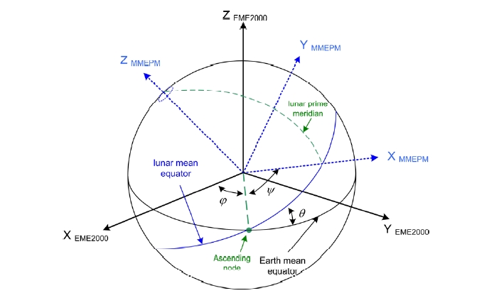
Before a spacecraft’s equations of motion with lunar non-spherical gravitation is established, an accurate coordinate for the Moon-centered system should be defined. Moon-centered coordinate systems are primarily used for operations in close proximity to the Moon. For bodies other than the Earth, the International Astronomical Union/International Association of Geodesy (IAU/IAG) gives the spin axis direction and the rotation of the prime meridian of each body using rotational elements as a function of time with respect to the Earth-centered Earth Mean Equator and equinox of epoch J2000 (E-EME2000) system. The E-EME2000 reference frame is often assumed to be identical to the International Celestial Reference Frame (ICRF) (Roncoli 2005). The recommended values for the direction of the north pole of rotation and the prime meridian of the Moon can be found in works by Roncoli (2005) and Seidelmann et al. (2007). Using the IAU/IAG-defined approximate expressions, the Moon-centered Moon Mean Equator and IAU vector of epoch J2000 (M-MME2000) coordinate system can be easily derived. In the M-MME2000 coordinate system, the Moon is the reference body, the Moon’s mean equator is the reference plane and the reference direction is the IAU vector to complete the M-MME2000 system. For a lunarbody-fixed coordinate system, two slightly different systemsexist: the mean Earth/rotation system (ME) and a principal axis (PA) system. The ME is a lunar body-fixed coordinate system based upon a mean direction to the Earth and a mean axis of the rotation of the Moon. The PA is a lunar body-fixed coordinate system aligned with the principal axes of the Moon (Roncoli 2005). The ME system is recommended because nearly all cartographic products of the past and present have been aligned to it (Davies & Colvin 2000). The difference in the coordinates of a point on the surface of the Moon between these systemsis approximately less than 1 km (Seidelmann et al. 2007). Coordinates in the ME reference system are consistentwith the IAU/IAG working group’s definitions. However, the ME systems are valid only in the approximately150-m level of accuracy (Konopliv et al. 2001). The procedures to approximate the PA system using the ME system by using the IAU/IAG’s right ascension, declination,and prime meridian equations is also indicated at literature by Konopliv et al. (2001).
For high precision work involving spacecraft operations, high-resolution mapping, and gravity field determination, a lunar ephemeris should be used to obtain the libration angles, not the IAU/IAG work, for the Moon from which the pole position and rotation can be derived. Actually, the precise lunar gravity field was developed using the lunar orientation specified by the JPL planetary ephemeris series in the PA system. On the ephemeris, the orientation of the Moon with respect to the Earth-centered Earth Mean Equator of J2000 (EME2000) is given by three Euler angles and their rates for PA system as follows (Seidelmann et al. 2007). The three Euler angles includeφ, the angle along the ICRF equator, from the ICRF X-axis to the ascending node of the lunar equator; θ, the inclination of the lunar equator to the ICRF equator; and ψ, the angle along the lunar equator from the node to the lunar prime meridian. Using the three Euler angles and their rates in the PA system, the acceleration due to lunar non-spherical gravitation can be modeled very precisely (Seidelmann et al. 2007).
Using the three Euler angles (φ,θ,ψ) and their rates (φ,θ,ψ) obtained from JPL planetary ephemeris, the conversion from the Moon-centered inertial position and velocity based on EME2000 (
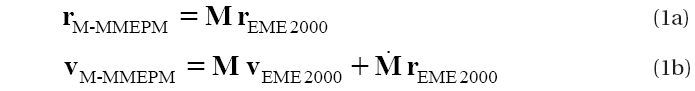
(Vallado & McClain 2001):
where M is the rotation matrix and can be expressed
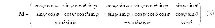
with Eq. (2):
In Eq. (2), M is the time derivative of M, and the inverse conversion from the M-MMEPM to the Moon-centered inertial position and velocity (based on EME2000)
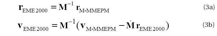
can be made with Eq. (3):
In addition, it is very important to keep in mind that the equations of motion are always integrated in the inertial frame, actually an approximated inertial frame, so the spacecraft state vector must be converted from the inertial frame to the body-fixed frame before the accelerations are computed due to the non-spherical gravitation.
For this study, M-MME2000 coordinate system is used for the inertial frame, and M-MMEPM coordinate in the PA system is used for the body-fixed frame. After the body-fixed accelerations are computed, they must again be converted back into the inertial frame to complete the equations of motion. Also, to account for accelerations due to point masses of other planetary bodies, the positions and velocities of planetary bodies derived with the JPL ephemeris should be converted to the Moon-centered inertial coordinate system (i.e., M-MME2000), since the JPL ephemeris provides the positions and velocities of planetary bodies with respect to
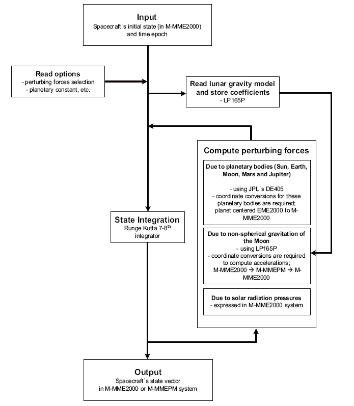
Using the definitions of a lunar reference frame as discussed, a precise lunar orbit propagator; YSPLOP is developed. This propagator is intended to design and analyze the spacecraft’s flying states in the vicinity of the Moon. The propagator calculates the accelerations due to the point masses of the Earth, the Moon, the Sun, Mars, and Jupiter. The non-spherical gravitation of the Moon and solar radiation pressures are also considered. Solar radiation pressures are computed with the dual cone model, and LP165P is used as for the lunar potential model. The JPL’s DE405 is used to derive the accurate planets’ ephemeris (Standish 1998). All planetary constants are used with the values defined by the JPL’s DE405. As for integration, the Runge-Kutta 7-8th variable step size integrator is used. Thirty-three seconds of a leap second,as of 2008, is used to compute the difference between ephemeris time and coordinated universal time (UTC). In following discussions,
4.2 Orbit propagator’s performance
The developed propagator’s performance is verified by comparing the results to the STK/Astrogator results. STK/Astrogator is widely used commercial software developed by the AGI Corporation to design and analyze interplanetary missions. To verify the performance of the developed propagator (YSPLOP), ?the initial lunar mapping orbit is assumed to be a circular lunar polar orbit, with 100 km of altitude with 90 degs of inclination at the Moon. The initial orbit epoch is assumed with 2020-1-1 00:00:00 (UTC). Seventieth degrees and orders (70 × 70) of the LP165P model are considered to compute acceleration due to the non-spherical gravitation of the Moon. Also, accelerations due to the point masses of the Earth, Moon, and Sun are considered. As the perturbing forces due to the point masses of the Mars and Jupiter and the solar radiation effect are almost negligible, these effects are omitted for this verification process.
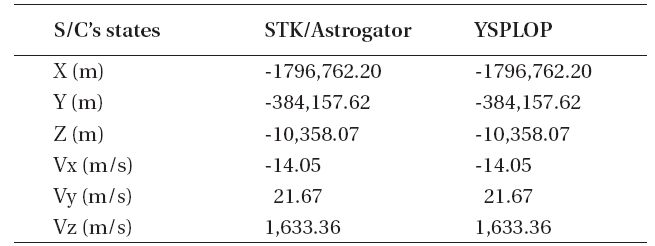
A propagation truncation error tolerance is set to have, ε=1×10-12, for both the developed propaga propagatorand STK/Astrogator. As for the first verification step, coordinate system transformation errors between the Earth and the Moon are checked. The initial states of the spacecraft in the inertial frame of the Moon are given as; 1,837,400.000 m for X position component (X), 1,633.505 m/s for z velocity component (Vz), and other state components,(Y),(Z), (Vx), and (Vy) are all zeros. Here, the inertial frame of the Moon indicates the M-MME2000 system. Table 1 shows the transformation results of YSPLOP and the STK/Astrogator. The spacecraft’s initial states (in M-MME2000 system) and the Earth and Sun’s ephemeris (in M-EME2000 system) at the initial orbit epochare transformed to the M-EME2000 system and M-MME2000 system, respectively. In this verification process,coordinate transformation errors for the spacecraft states as well as the Sun and the Earth’s states should be checked, since their states are directly used to compute the perturbing accelerations. As shown in Table 1, errors due to the coordinate transformations between YSPLOP and STK/Astrogator are less than m or m/s for the Earth, less than several tens of m or m/s for the Sun.
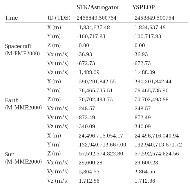
Coordinate system transformation results for YSPLOP and STK/Astrogator. The spacecraft’s initial states (in M-MME2000 system) and the Earth and Sun’s ephemeris (in M-EME2000 system) are transformed to M-EME2000 and M-MME2000 system, respectively.
The accumulation of very small numerical truncation errors in along-track velocity components may finally result in relatively larger errors than the other components, since the along-track velocity component of the initial orbit itself had a large value, as it is a circular orbit, than the radial or cross-track components. Additionally, typical orbit uncertainties due to the lunar gravity model for the LP nominal mission were 0.5 m in the radial direction and 5 m in the other two directions, along and normal directions (Carranza et al. 1999). Numerous results shown above confirm that the developed propagator performs very accurate coordinate conversions and also accurately propagates the trajectory. Although functional aspect between the developed YSPLOP and STK/Astrogator is almost same, the developed YSPLOP has still important meanings. With through simple modifications, YSPLOP can be widely applied for more advanced design and analysis tools for any mission that operates very close proximity to the Moon, which cannot be done with just using the STK/Astrogator.
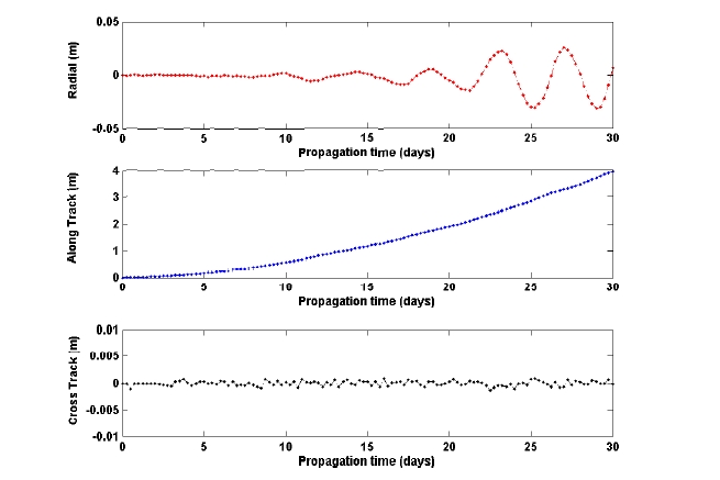
The coordinate system transformation errors between the M-MME2000 and the M-MMEPM system (based on PA) for the spacecraft’s initial states are also shown in Table 2. Generating very accurate transformations from M-MME2000 to M-MMEPM is very important for deriving accurate perturbing forces due to the Moon’s non-spherical gravitation. With the spacecraft’s initial states as discussed, the given lunar mapping orbit is propagated for 30 days. As the initial orbit has a period of 118 min, the lunar orbiter will revolute the Moon about 336 times during the 30 days of propagation. Additionally, during the 30 days of propagation, the orbiter will map the complete areas of the lunar surface as one lunar rotational period is about 27.32 days. Fig. 3 compares the propagation results between YSPLOP and STK/Astrogator. In Fig. 3, the spacecraft’s state differences are derived to have radial, along-track, and cross-track components in the M-MME2000 frame. The maximum error between YSPLOP and STK/Astrogator is about 4-m in the along-track direction, in 30 days of propagation. It seems that these errors are due to the accumulation of the numerical truncation errors of the propagator, especially in the along-track direction.
Coordinate system transformation results for YSPLOP and STK/Astrogator. The spacecraft’s initial states in M-MME2000 are transformed to the M-MMEPM system.
The accumulation of very small numerical truncation errors in along-track velocity components may finally result in relatively larger errors than the other components, since the along-track velocity component of the initial orbit itself had a large value, as it is a circular orbit, than the radial or cross-track components. Additionally, typi-cal orbit uncertainties due to the lunar gravity model for the LP nominal mission were 0.5 m in the radial direction and 5 m in the other two directions, along and normal directions (Carranza et al. 1999). Numerous results shown above confirm that the developed propagator performs very accurate coordinate conversions and also accurately propagates the trajectory. Although functional aspect between the developed YSPLOP and STK/Astrogator is almost same, the developed YSPLOP has still important meanings. With through simple modifications, YSPLOP can be widely applied for more advanced design and analysis tools for any mission that operates very close proximity to the Moon, which cannot be done with just using the STK/Astrogator.
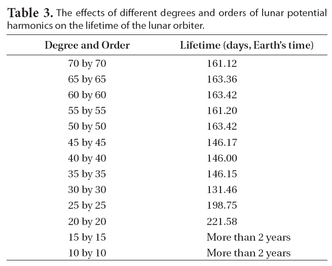
The effects of different degrees and orders of lunar potential harmonics on the lifetime of the lunar orbiter.
5. LIFETIME ANALYSIS FOR LUNAR POLAR ORBITER
5.1 Effects of the Moon’s non-spherical gravity
Using developed precise orbit propagator (YSPLOP) as discussed in previous subsection, analysis of the lunar polar orbiter’s lifetime is performed. Various degrees and orders of lunar potential harmonics are considered to see how they affect the lifetime of the lunar orbiter. Numerous simulations are performed, with an increase of the degree and order of lunar potential harmonics by 5 ×5, including the Moon as a point mass. The effects of the different degrees and orders of lunar potential harmonics on the lifetime of the lunar orbiter are shown in Table 3. To derive the lifetime of the lunar orbiter, the orbiter is assumed to crash on the Moon’s surface when the radius of perilune is less than the mean radius of the Moon (about 1,738.4 km).
As shown in Table 3, different degrees and orders of lunar potential harmonics significantly affect the lifetime of the lunar polar orbiter. After considering the 50 × 50 degrees and orders field, the lifetime of the lunar polar orbiter remains about 160 days, and no more significant lifetime differences are observed. Indeed, a lunar polar orbiter’s lifetime with the LP100J model (with 100 × 100 degrees and orders field) was about 160.4 days (Manglik 2005). Thus, to design and analyze lunar orbiter missions, at least a 50 × 50 degrees and orders field should be considered, which are the same values as discussed in Roncoli’s (2005) work. For general mission design studies involving lunar orbiters with altitudes as low as 100 km, Konopliv et al. (1993) suggested that a 40 × 40 field is sufficient to represent the lunar gravity field. In more recent literature, Roncoli (2005) suggested to use a minimum 50 × 50 degree and order field for orbits with altitudes in the range of 30-100 km.
5.2 Effects of third body gravity
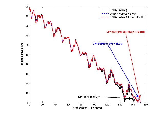
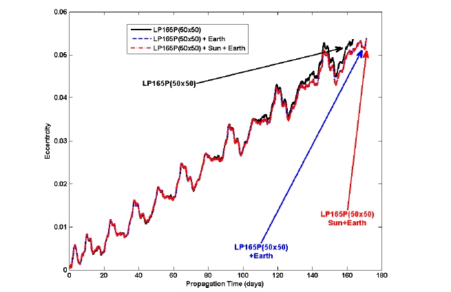
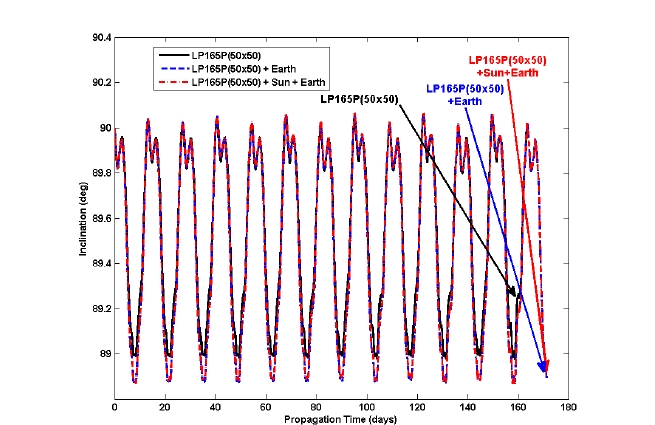
As we have concluded that at least a 50 × 50 degrees and orders field is sufficient to represent the lunar gravity field for a precise lunar orbiter mission, other major perturbing forces such as the point masses of the Earth and the Sun are included to see how they affect the lunar orbiter’s lifetime. In Figs. 4-6, the altitude of periapsis (ph), inclination (i), and eccentricity (e) variations due to the effects of the point masses of the Earth and the Sun in the lunar polar orbits are shown. As already shown in Table 3, the lifetime of the lunar polar orbiter (with a 100 km altitude, polar orbit at the Moon) was found to be about 163.42 days when the degrees and orders of 50 × 50 of the lunar gravity field are regarded. However, when a perturbing force due to the point mass of the Earth is included, the lifetime is about 171.21 days, about a 7-day extension. However, the effect of a perturbing force due to the point mass of the Sun on the lifetime of the lunar polar orbiter is found to be almost negligible. The extensions of the lunar polar orbiter’s lifetime due to the point masses of the Earth and Sun were already discussed by Meyer et al. (1994). The results derived in this subsection indicate that the gravitational attractions due to the point mass of the Earth cannot be ignored while designing detailed missions for lunar polar orbiters with an altitude of about 100 km.
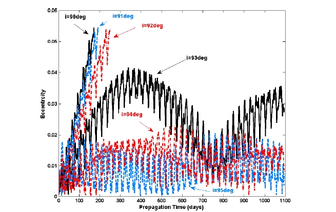
5.3 Effects of the orbital inclinations
In subsections 5.1 and 5.2, it is found that the different degrees and orders of the Moon’s non-spherical gravitational perturbation, as well as the perturbation due to a point mass of the Earth, seriously affect the lunar polar orbiter’s flight dynamics. Most of the past lunar orbiting missions were performed with lunar polar orbit (
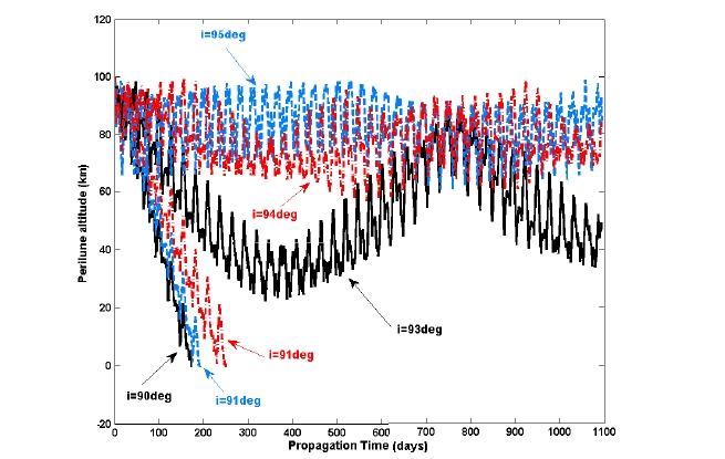
Interestingly, as shown in Figs. 7 and 8, the lifetimes of circular lunar mapping orbits with inclinations about 93, 94, and 95 degs are found to be more than 3 years, which are great extensions of lifetime compared to 90 deg inclined case. However, the cases with the 94 and 95 degs seem to more profitable for lunar mapping missions since they have less variation in perilune altitudes and orbital eccentricities. Lesser variations in perilune altitudes and orbital eccentricities mean that the orbital shapes remained constantly nearly circular, which are very important factors for mapping missions, as for orbital maintenance as well as the operational complexity. For the case of inclinations in the range of 85-90 degs, again, at the inclination of 85 deg, the lifetime of the near polar lunar orbiter is shown to be more than 3 years. Other than the 85 deg inclination, no extreme extensions of lifetime have been observed. However, from the point of efficiency for mapping missions, 94 or 95 degs of inclination is still preferable to the 85 deg inclination, since they showed lesser variations in perilune altitudes and orbital eccentricities. Extreme extension of the lifetime for near polar lunar orbiter, with altitude about 100 km and inclinations of 94, 95, or 85 degs, seems strongly correlated to different accelerations acting from the lunar surface. Recent literature about the Moon’s gravity field analysis (Konopliv et al. 2001) showed that there exist several regions where the accelerations due to the Moon’s gravity fields are stronger than other local lunar surface regions. Two major regions are located where the lunar surface accelerations are relatively strong; at the northern hemisphere of the Moon (within the Moon’s longitude boundary of ±30 degs). The locations of two major strong “attracting” regions might affect the near polar lunar orbiter’s lifetime. However, more profound analysis on lunar gravimetry should be performed to analyze the reasons why the lunar near polar orbiter’s lifetime are extended at a certain orbital inclination. The overall aspects of the derived results confirm that a little difference in a lunar mapping orbit’s inclination would result in a big extension of the lunar orbiter’s lifetime. However, the selection of a lunar mapping orbit’s inclination strongly depends on the mission requirements for the given mapping missions.
In this paper, analyses of lunar mapping orbits are performed. To analyze the lunar mapping orbit’s characteristics, the precise lunar orbit propagator; YSPLOP is developed. In the propagator, accelerations due to the Moon’s non-spherical gravitation, the point masses of the Earth, Moon, Sun, Mars, Jupiter and also, solar radiation pressures can be included. Also, to implement the Moon’s non-spherical gravitation, highly accurate co-ordinate transformation formula to the Moon-centered coordinate system is used.
The developed lunar orbit propagator’s performances are validated using results derived from STK/Astrogator. The results of the developed propagator showed a very good match to the results from STK/Astrogator. Only about 4-m differences are observed in the along-track direction, after 30 days (Earth’s time) propagation of the circular polar lunar mapping orbit with 100 km altitude, with the perturbing forces of 50 × 50 degrees and orders of the LP165P model and the point masses of the Earth and the Sun.
The lifetime, as well as the orbital characteristics, of a lunar polar orbiter is strongly affected by the different degrees and orders of the lunar gravity model, and by a third body’s gravitational attractions; especially the Earth. Therefore, for precise lunar mapping orbit analysis, at least the degrees and orders of 50 ×50 for the lunar gravity model should be considered as well as the gravitationalattractions due to the point mass of the Earth. The usual lifetime of circular polar orbits around the Moon is about 160 days (Earth’s time) with an inclination of 90 degs. However, the lifetime of a circular, near polar orbit around the Moon with about 95 degs of inclination was found to be more than 3 years (Earth’s time).
The developed precise lunar orbit propagator can be used as the basic algorithm for advanced missions operatingvery close proximity to the Moon. For example, a lunarlanding mission that requires very accurate controls to target a precise landing point on the Moon’s surface, or can be utilized to derive very precise frozen and sun-synchronous orbit conditions, or can be used to design orbit constellations around the Moon.
This work is supported by the Korea Aerospace Research Institute (KARI) through 'Development of Preliminary Lunar Mission Trajectory Design Software" project (No. FR09510).