As a preparatory study for Global Positioning System-Very Long Baseline Interferometry (GPS-VLBI) hybrid system, we examined if VLBI type observation of the GPS signal is realizable through a test experiment. The test experiment was performed between Kashima and Koganei, Japan, with 110 km baseline. The GPS L1 and L2 signals were received by commercial GPS antennas, down-converted to video-band signals by specially developed GPS down converters, and then sampled by VLBI samplers. The sampled GPS data were recorded as ordinary VLBI data by VLBI recorders. The sampling frequency was 64 MHz and the observation time was 1 minute. The recorded data were correlated by a VLBI correlator. From correlation results, we simultaneously obtained correlation fringes from all 8 satellites above a cut-off elevation which was set to 15 degree. 87.5% of L1 fringes and 12.5% of L2 fringes acquired the Signal to Noise Ratios which are sufficient to achieve the group delay precision of 0.1nsec that is typical in current geodetic VLBI. This result shows that VLBI type observation of GPS satellites will be readily realized in future GPS-VLBI hybrid system.
Space geodetic technique is the geodetic technique that precisely measures the shape of the earth and its movement by observing celestial bodies or artificial satellites. The representative techniques include Very Long Baseline Interferometry (VLBI), Global Navigation Satellite System (GNSS), Satellite Laser Ranging (SLR) and Doppler Orbitography and Radiopositioning Integrated from Space (DORIS). Since the individual Space geodetic techniques are limited in the parameters that can be determined depending on the object and method of the observation, combination of the space geodetic techniques is required to be able to determine all the parameters related to the shape of the earth and its movement. The combination of the space geodetic techniques can be classified into different levels such as product level, normal equation level and observation level, depending on the object and the manner of the combination. The product level combination is to express the independent coordinates of stations determined by each of the techniques in a one, combined coordinate system. Since it employs a simple coordinate transformation method it can be simply realized. This combination method is applied by International Earth Rotation and Reference Systems Service (IERS) to produce International Terrestrial Reference Frame (ITRF) at present (Altamimi et al. 2002). However, because it does not consider the observation models of the individual techniques, it is less accurate compared to the lower level combination methods. The normal equation level combination is recently drawing attention since it allows the combination of each parameter considering the observation models of the individual techniques (Vennebusch 2008). However, it is not a perfect combination method because this method cannot separate the error characteristics of individual techniques included in the observation data themselves. The observation level combination is essentially the most ideal combination method that homogenizes the observation data by ensuring the same observation conditions of the individual techniques as much as possible and thus removing the difference in the error characteristics of each technique. However, it is relatively difficult because high-level understanding of the individual techniques is required in order to realize the identical observation conditions and additional equipments for the identical observation should be newly developed.
Recently, for the observation level combination, several studies have been carried out to install a GPS antenna to a VLBI antenna or to add a GPS feed to a VLBI antenna (Thaller & Rothacher 2002, Petrachenko et al. 2004, Tornatore & Hass 2010). However, when a GPS antenna is installed to a VLBI antenna, a problem arises that the reference point of the GPS antenna is no longer a fixed point on the earth but moves as VLBI antenna change its orientation. Moreover, the uniformity of the observation condition is lacking because the signals are processed in the conventional GPS method. On the other hand, when the GPS signals are received with the VLBI antenna, the VLBI antenna, which is directional, can receive the signals from only one GPS satellite at one time. Such an observation method is not efficient when it is compared with the general GPS method that receives several satellites signals simultaneously using the omni-directional antenna. Moreover, considering the advantage of VLBI that highly accurate station position, International Celestial Reference Frame (ICRF) and Universal Time 1 (UT1) are determined by the continuous observation of stable quasars, addition of GPS feed for the GPS satellite signal reception will decline the performance of the VLBI. Therefore, the most efficient combination method is to perform sampling, recording and correlation in the same manner, while maintaining advantageous characteristics for radio-wave reception in each of the observation techniques. In this paper, we suggest the GPS-VLBI hybrid system in which GPS and VLBI are combined in this way as a unified observation system. This is the concept that is proposed for the first time in the world (Kwak et al. 2008a, b, 2010) and the present study is the first actual test observation for realizing the concept.
GPS-VLBI hybrid system can obtain more data than a single technique and provide the effect of reducing the number of clock parameters to the half by using the same frequency standard. These characteristics are expected to improve the estimation of the atmospheric propagation delays that vary rapidly in time and thus elevate the precision of VLBI geodesy. The combination of VLBI technique that determines ICRF and the GPS technique that determines the orbit of the GPS satellite will allow expressing the GPS satellite orbit directly on ICRF. In addition, the combination of GPS which determines the center of the earth and VLBI which determines only the relative baselines of the antennas will enable to connect the VLBI TRF to the center of the earth directly (Dickey 2010). Moreover, through the hybrid system, GPS will contribute to the determination of the long periodic UT1 components, one of the earth rotation parameters.
The objective of this study is to verify experimentally if it is possible for GPS to observe in the VLBI way from the viewpoint of hardware, which is the prerequisite for the realization of GPS-VLBI hybrid system. In this article, we verified the detection of each correlation fringe from every GPS satellite and discussed the Signal to Noise Ratio (SNR) of the correlation fringe and the thermal noise errors of the group delay and the delay rate.
2.1 Overview of the observation system
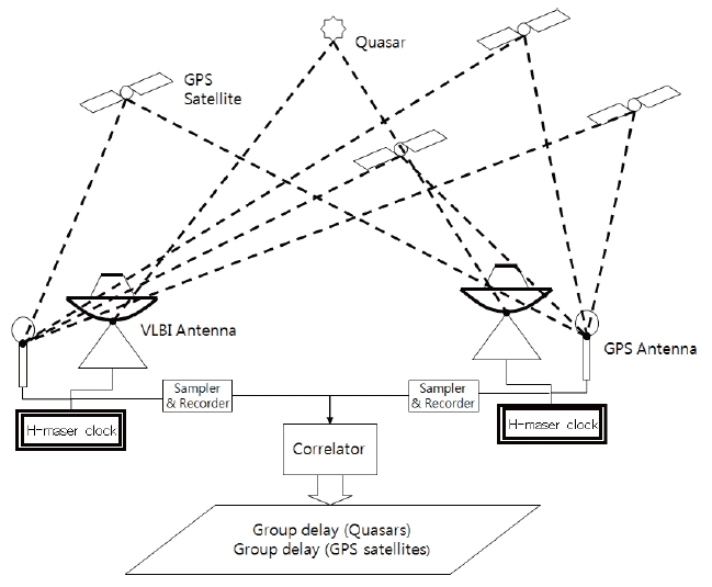
GPS-VLBI hybrid system is the observation level combination system for the GPS technique and VLBI technique in the same site. It receives the quasar signals through the VLBI antenna and the satellite signals through the GPS antenna, respectively, and generates data with the down converters and the VLBI sampler that are operated based on the same reference signals provided by the hydrogen atomic clock. The VLBI and GPS data generated by the VLBI sampler are recorded in the same format in the VLBI hard disk recorder. These VLBI-format observation data transferred from individual stations are correlated by the VLBI correlator and the delay between the stations is eventually produced (Fig. 1).
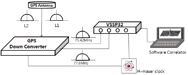
For VLBI type GPS test observation, a commercial GPS antenna was used in receiving the GPS signals. In ordinary GPS observations, a sequence of signal processing and data generation is automatically carried out in the commercial GPS receiver. Therefore, an additional GPS down converter is required for the signal processing in VLBI type observation. The GPS down converter for the GPS-VLBI hybrid system was specially designed and fabricated in National Institute of Information and Communications Technology (NICT) (Fig. 2) (Amagai 2009). The GPS down converter of NICT converts the L1 (1,575.42 MHz) and L2 (1,227.6 MHz) signals into frequency bands with central frequencies of 75.42 MHz and 77.6 MHz, respectively. The bandwidth of each channel is 32 MHz which can include all the GPS signals. The down-converted GPS signals are recorded as the VLBI formatted data through the Versatile Scientific Sampling Processor 32 (VSSP32) (Kondo et al. 2008) which is the VLBI sampler and recorder developed by NICT. During these procedures, the GPS down converter and the sampler are provided with the reference signals from the hydrogen atomic clock as the general VLBI systems. The VLBI software correlator developed by NICT (Kondo et al. 2003) was used to correlate the GPS data recorded in VLBI format.
2.2 Outline of the observation
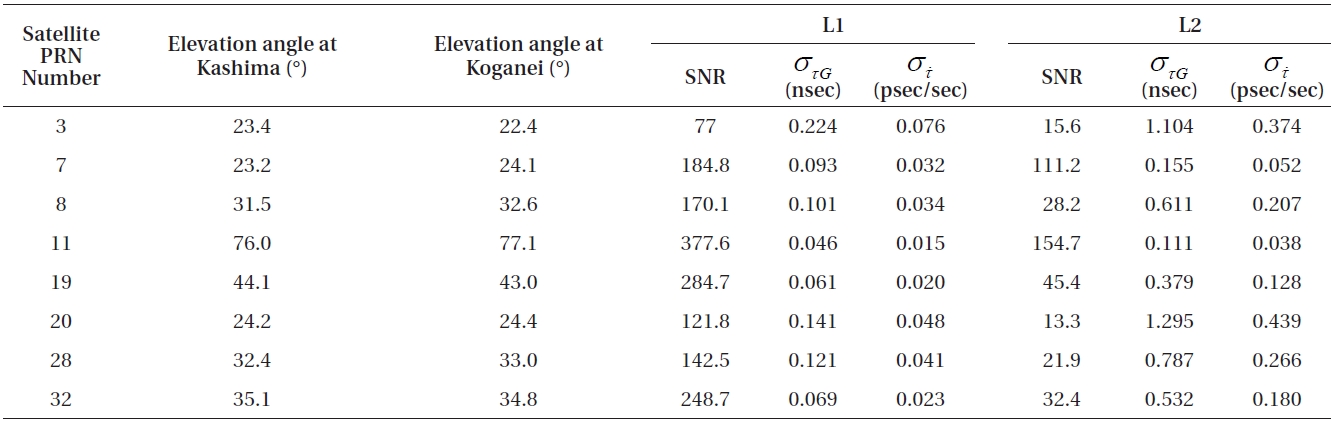
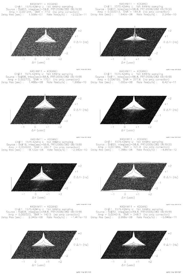
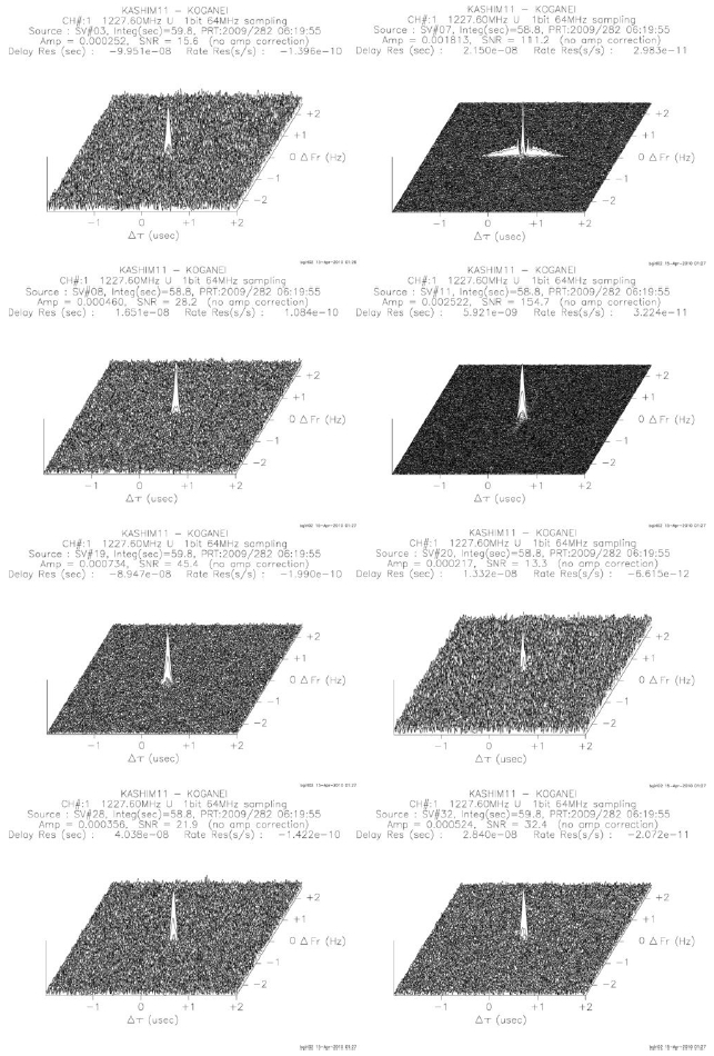
The VLBI type GPS test observation was carried out in between Kashima and Koganei, Japan, for one minute, 06:19:00-06:20:00 UTC, on October 9, 2009. The baseline length between the two stations was 110 km, approximately. Since the signals from the satellite of which elevation angle is small are greatly affected by the atmosphere, the cut-off elevation angle was set up as 15 degrees. Total 8 satellites whose elevation angles were higher than 15 degrees appeared on the celestial hemisphere above the two stations during the observation. The Pseudorandom Noise(PRN) numbers of observed satellites and their elevation angles at the time of observation are listed in Table 1. All the satellite signals were recorded within the 32 MHz bandwidth at once.
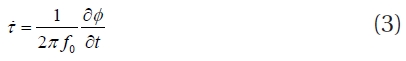
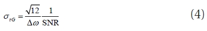
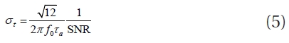
Because we use the omni-directional antenna for GPS observation, different signals from the individual satellites are received together. Thus, VLBI type observation of GPS signals can be evaluated as to be successful if the correlation fringes of individual GPS satellites signals are separately detected through the VLBI correlation. In addition, the feasibility of the hybrid system in geodesy can be evaluated by examining the expected precision of group delay (τG) and delay rate (τ) of the GPS signals through the SNR analysis of the detected correlation fringe.
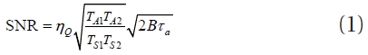
The SNR of the correlation fringe detected after the correlation is determined as the Eq. (1) (Thompson et al. 2001), where τQ denotes the efficiency of converting the analog signal to the digital signal,

As the results of the correlation of the test observation data with the VLBI correlator, distinctive fringes were successfully detected simultaneously from all the 8 satellite whose elevation angles were larger than 15 degree (Figs. 3 and 4). The results imply that the VLBI system using the GPS antenna is able to process the GPS signals, no matter the magnitude of the error may be. Hence, the hardware constitution of the GPS-VLBI hybrid system is reasonable.

The elevation angles of the satellites observed from the two stations at 06:19:00 UTC, the SNR, and the thermal noise errors of the group delay and the delay rate of each signal during 1 minute of integration time.
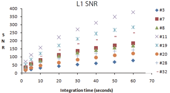
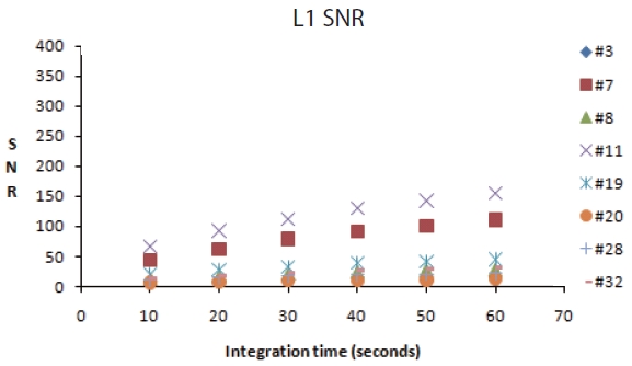
Assuming that the Allan standard deviations (Thompson et al. 2001), which show frequency stability, of the hydrogen atomic clock and the atmospheric delay of general VLBI system are 10-15 and 10-13, respectively, the allowable integration time of the GPS L1 and L2 signals without losing the phase coherence could be as large as 1,000 seconds. However, if our delay prediction model for the correlation processing is not accurate enough, coherence loss can take place in a shorter integration time. Therefore, we examined in this study whether the coherence was maintained in the GPS correlation results by comparing the SNR values obtained with various integration times within 1 minute. The variation of the SNR of the correlation fringe of each satellite depending on the correlation integration time is shown in Figs. 5 and 6. The results showed that the SNR of the correlation fringe increased as the correlation integration time increased. It is because, when there is no loss of coherence and ,ηQ,

as implied from the Eq. (1). This result shows that the coherence loss due to the imperfect delay prediction model, along with the variable clock and atmosphere, is sufficiently small in the VLBI type GPS observation. Table 1 shows the SNR values of the correlation fringes of the individual satellites when the observation data were integrated for 1 minute. The observation for 1 minute showed that the SNR of the GPS L1 signal was in the range of 77∼377.6 and that of the GPS L2 signal was in the range of 13.3∼154.7. The large difference between the SNRs of the two signals is due to the difference of the signal intensity itself because two kinds of code, the P code and the C/A code are carried by the L1 carrier, while only the P code is carried by the L2 carrier (Spilker 1996). In addition, since the C/A code is a narrowband (1.023 MHz) signal, the detected width of the fringe peak was wider. The large difference among the SNR values from the individual satellites is presumably because of the variation in the signal reception sensitivity depending on the position of the satellites and the features on the earth since the GPS antenna is omni-directional. The GPS antenna receives the artificially transmitted signals from the satellites and thus the SNR values are much larger than that of VLBI that receives the weak noise signals from astronomical radio sources. Table 1 shows that, except the PRN number 3, the L1 signal whose signal intensity is relatively strong has the group delay thermal noise error which is in similar level to that of VLBI. In addition, the L2 signal of which signal intensity is relatively weak showed larger error than that of the normal VLBI observation, except the PRN number 11. For the delay rate, both L1 and L2 signals showed larger error than the general VLBI thermal noise error. However, if only the phase coherence is maintained, the error can be improved by increasing the integration time.
These results were obtained on the basis of compatibility of VLBI systems and simultaneous processing of the large-volume data achieved thanks to the recent development of the signal processing technology. We confirmed that there is no big restriction in processing the GPS signals in the VLBI system. That means the combination with the GPS antenna in the VLBI system can bring the equivalent effect to installing additional VLBI antennas, if only the prediction model is accurate.
As a preliminary study for GPS-VLBI hybrid system development, we examined if the VLBI type observation of the GPS signal is realizable. The equipments of the conventional VLBI system were used without change except the GPS antenna and the GPS down converter. We successfully separated GPS signals from individual satellites by correlating the GPS data recorded in the VLBI format and obtained the distinctive correlation fringes. Moreover, the precision analysis showed that the precision was almost similar to the general geodetic VLBI precision and it was confirmed that, even if the result has low precision, there is a possibility to improve the precision by increasing the correlation integration time. The significance of this study is that it was proved for the first time in the world, by an actual observation, that the VLBI type observation of the GPS signal is feasible without any difficulty in the hardware and has the potential to achieve the VLBI precision. It is expected that the GPS-VLBI hybrid system can greatly contribute to improving the VLBI precision together with the multiple antenna system proposed in the VLBI2010 (Petrachenko et al. 2004) in the future.