Satellite laser ranging (SLR) is the technology to precisely measure the distance between a point on the earth and a satellite by emitting laser in an extremely short duration from a telescope on the earth to a satellite, retro-reflecting the light with a laser retroreflector on the satellite, and measuring the time taken by the light signal returning to the telescope on the earth to travel back and forth. A transmission and reception telescope is required to transmit and receive laser light and it should be precisely operated according to the satellite velocity for the tracking of the satellite and measuring of the distance. For this, development of a robust and precise high-speed tracking mount is necessary and the design technology for such a tracking mount is one of the important factors that determine the accuracy of distance measurement of the SLR system.
At present, Korea Astronomy and Space Science Institute (KASI) is developing an altitude-azimuth type movable SLR system (ARGO-M) and Korea Institute of Machinery & Materials (KIMM) is developing the tracking mount to operate it. The major elements of tracking mount include mount structure, optical interface and axis-driving part. The mount structural design having a natural frequency higher than a certain level as well as a precise drive and control system with fast response is required to point and track the target satellite rapidly and precisely overcoming disturbances such as wind and bearing friction (Park et al. 2005, Gawronski 2004, Han & Nam 1998). The drive and control system consists of driving motor, encoder, motor driver and position/speed controller.
In this article, we defined the requirements on the performances of the tracking mount for a movable SLR system and presented the results of selecting the core parts of the tracking mount structure and the precision driving-controlling system to meet the requirements. Based on these, we manufactured simulator for the elevation axis to verify the results of the design and evaluated the tracking performance and the system accuracy (Jeong et al. 1999).
2. PRELIMINARY DESIGN OF THE ARGO-M TRACKING MOUNT
2.1 The specifications on the design requirements for ARGO-M tracking mount
The mounts used for astronomical telescopes are classified into altitude-azimuth types and equatorial types. Because SLR needs to transmit and receive laser light, the mount is necessary for SLR system as in the cases of astronomical telescopes, since it also needs to transmit and receive laser light by means of a telescope. Most of the SLR systems that have been developed by foreign countries have adopted the altitude-azimuth type tracking mount and developed it in their own shapes.
[Table 1.] The specifications on the design requirements for ARGO-M tracking mount.
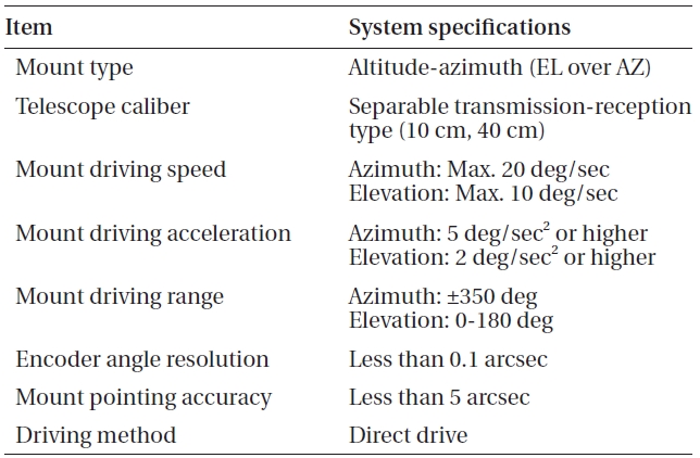
The specifications on the design requirements for ARGO-M tracking mount.
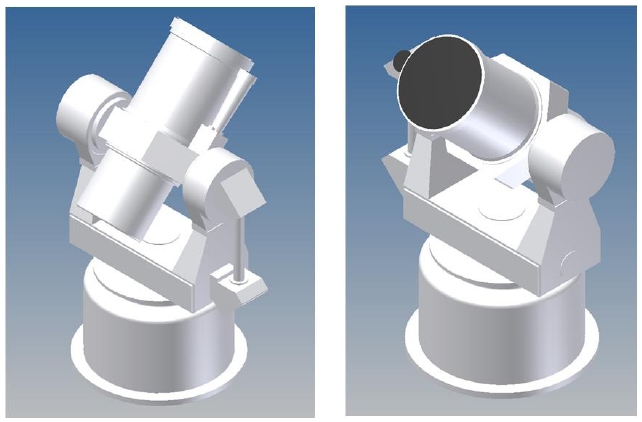
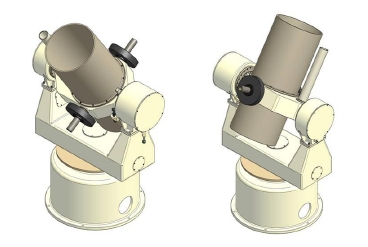
The main parts that consist of a tracking mount are the mount base and frame, optical interface and axis-driving part. The each mechanisms as well as the manufacturing and assembling accuracy should be highly accurate. Particularly, it is necessary to design each of the driving axis structures so that it may have structural robustness and stability through the static, dynamic and thermal structural analysis of the tracking mount. In addition, straightness between the elevation axis and the azimuth axis, alignment accuracy of the optical system and robustness of the telescope tube body structure are the important design factors to secure the target-pointing accuracy of the SLR system. The shape of the ARGO-M mount basically needs to support the reception optical system of 40 mm-caliber and the transmission optical system of 10 mm-caliber, and should be designed to meet the following design requirements: (1) The SLR system tracking mount should have the altitude-azimuth type shape to move the transmission-reception optical system to the desired locations by operating both the elevation axis and the azimuth axis simultaneously. (2) The tracking mount should basically transmit and receive laser light by means of optical telescope. Thus, the reception optical system with a large reflector in a certain caliber, the transmission optical system to emit laser, and the optical waveguide to send the received light to the electronic measurement and analysis equipment must be installed within the mount. (3) Considering the caliber and properties of the optical systems as well as the pathway of the optical waveguide, the mount shape should be designed in the separable transmission-reception type. Considering these requirements, the specifications on the design requirements of the ARGO-M tracking mount are listed in Table 1. As shown in Fig. 1, we have carried out the preliminary design of the mount shape reflecting the specifications on the design requirements.
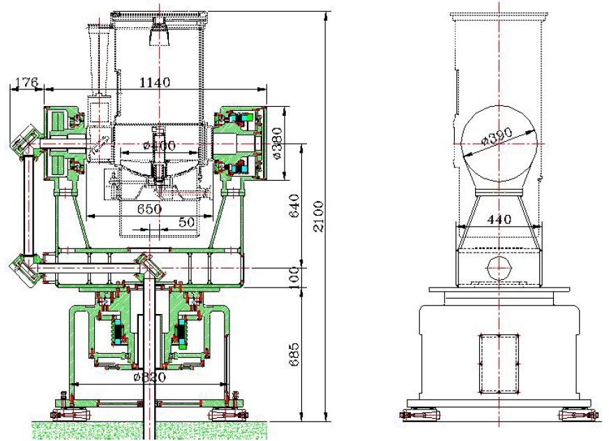
Fig. 2 shows the dimensions of the outer shape of the preliminary mount design. The maximum height is 2,100 mm, the width is 1,316 mm, and it is misaligned by 50 mm in between the optical systems and the mount azimuth axis to be at the mass center of the payload. This shape can be modified based on the shape and the dimensions of the optical systems.
2.2 Selection of the core parts for the axis driving in the ARGO-M tracking mount
The axis-driving part of the tracking mount should be designed in the mechanism that can secure the mechanical driving accuracy by minimizing the mechanical friction caused by the rotation, have the mechanical structure that is simple and highly structure-stable as much as possible and be convenient for the maintenance. In addition, the required level of repeatability should be achieved by minimizing the factors such as backlash, for example, by reducing the number of mechanical transmitting elements, that may hinder the precise driving. Further, to secure the beam waveguide pathway for the laser transmission and reception, it should be designed in hollow type. To meet these requirements, direct drive motor and high-resolution encoder should be employed and high accuracy level bearings with high run-out and wobble accuracy should be selected to be applied to the mount.
2.2.1 Selection of the axis driving motor
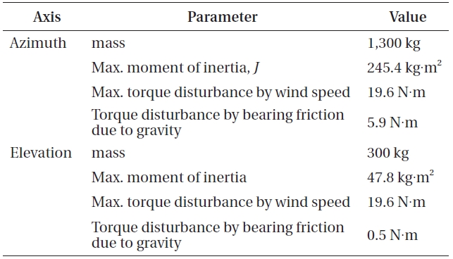
[Table 2.] The mechanical specifications applied to the calculation of the required torque.

The mechanical specifications applied to the calculation of the required torque.
Axis driving motor is the part to drive the elevation axis including the transmission-reception telescope as well as the azimuth axis that supports the payload of the entire telescope including the mount frame and the peripheral devices depending on the required driving speed and acceleration of the tracking mount. In the system that requires high-torque driving and high-precision position control characteristics, such as SLR system, the direct drive motor tends to be used since it has good starting torque, generates high torque at low speed, and shows good mechanical dynamic characteristics. Since such a direct drive motor is installed as a part of the mechanical system, without a frame, axis-driving mechanism can be simplified. In order to select the direct drive motor for ARGO-M, a simulation was carried out by applying the mechanical specifications in Table 2 and and using the Matlab/Simulink shown in Fig. 3. The wind pressure disturbance condition was set at 14 m/s of wind speed, and the sinusoidal profile was employed as the speed/acceleration profile for the pointing in order to minimize the residual vibration due to the acceleration and deceleration, in the simulation (Schipani & Mancini 2002).
[Table 3.] The equipment specifications applied to the calculation of the required torque.
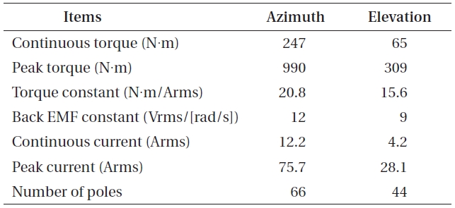
The equipment specifications applied to the calculation of the required torque.
The simulation results predicted that the maximum torque requirement of azimuth axis and elevation axis would be approximately 114N-m and 30N-m each. Considering the torque requirement predicted by the simulation and the safety factor, the motor with the specifications shown in Table 3 was selected as the motor that would be actually applied to the tracking mount. Fig. 4 shows the outline dimensions of the selected motors for each axis (ETEL Motion Technology 2008).
2.2.2 Selection of encoder
Encoders, angle detection sensor with high position resolution, are absolutely required to perform the driving control of the ARGO-M tracking mount in high accuracy using the axis driving motor. The encoder signals are fed back to the servo control system. The major requirements of the encoder that is to be applied to the azimuth axis and the elevation axis can be summarized as followings: (1) An optical encoder with a highly angle resolution should be selected to achieve the requirement of the satellite tracking accuracy. (2) Since the encoder alignment affects the control accuracy, it should be convenient to assemble and align to the mechanical structure. (3) The encoder should be optical incremental type and the angle resolution should be less than 0.1 arcsec considering the control and mechanical deviation in order to achieve the pointing accuracy of the mount. (4) An adaptor should be fabricated for the accurate alignment between the motor and the encoder so as to precisely detect the motion of the driving motor in relation with the motor in the axis driving part.
[Table 4.] The specifications of the selected encoders.
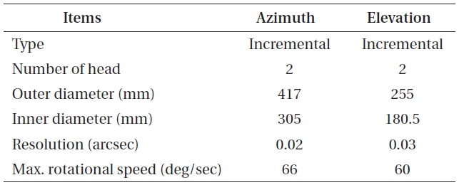
The specifications of the selected encoders.
Encoders can be classified into absolute encoders and incremental encoders. One advantage of absolute encoder is that the present position of the rotational axis can be read even in the case of electric power resupply. However, most of the commercial absolute encoders that have been developed until now can be applied to small scale system that is less than 200 mm of outer diameter. In addition, since a ring type product that can be independently attached to the rotational axis is not available, the supporting structure for the encoder case is required, which makes the installation procedure complicated. In contrast, in the case of incremental encoder, the installation is simple because the ring type encoder can be directly attached to the rotational axis.
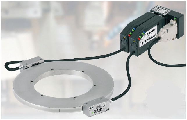
A tape type of incremental encoder can be easily installed regardless of the outer diameter of the rotational axis, even to a large scale system. Plural encoder read heads are applied only to incremental encoder at present. Although incremental encoder needs additional sensor to find out the present position in the case of electric power resupply, it is suitable to large systems requiring high accuracy in the assembly and measurement such as SLR system.
Reflecting the considerations above, an incremental encoder with two read heads that can be easily installed was selected, and the specification and the outer shape are shown in Table 4 and Fig. 5.
2.2.3 Selection of bearing
Bearing is required to rotate the tracking mount, being combined with the torque motors of the azimuth axis and elevation axis and supporting the weight of the tracking mount. Hydrostatic bearings are generally applied rather than mechanical bearings to large scale astronomical telescopes due to the large weight loaded to the azimuth axis. Since most of the SLR systems are meso-scale systems adopting 0.6-1 M of telescopes and the weight load to the azimuth axis is about 3-4 tons, mechanical bearings are usually applied. Precise bearings should be selected because the run-out accuracy and wobble of bearings have big influence on the SLR tracking accuracy. The bearing design requirements are as follows: (1) The bearings should have the strength enough to support the expected change of the weight due to disturbances as well as the axial and lateral load of the azimuth axis and elevation axis of the mount. (2) The bearings should be of ultra-high accuracy level with less run-out and wobble so as to achieve the target pointing accuracy of the mount, minimizing the rotational friction depending on the axis drive motor speed and torque.
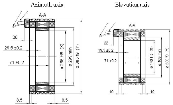
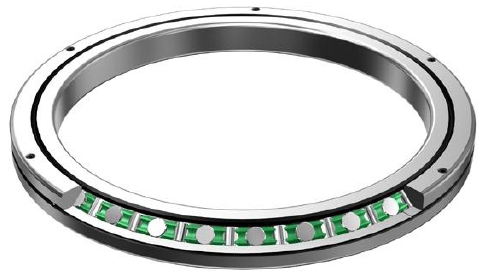
Foreign SLR systems usually adopt angular contact ball bearings, but cross-roller bearing that is usually used in ultra-high precision systems was selected as the drive axis bearing of ARGO-M. Since the rollers are in orthogonal array in the cross-roller bearing, one bearing is enough to sustain both the journal and thrust weights, different from the angular contact ball bearings that are multi-aligned. Considering the diameters of the ARGO-M azimuth axis and elevation axis and their weights, a cross-roller bearing with the specifications and outline in Table 5 and Fig. 6 was selected.
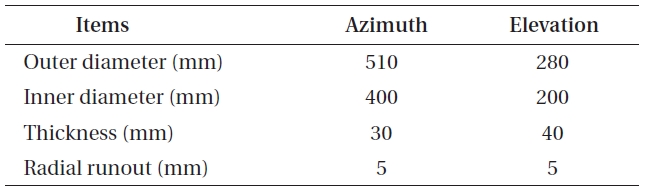
[Table 5.] The specifications of the selected cross-roller bearing.

The specifications of the selected cross-roller bearing.
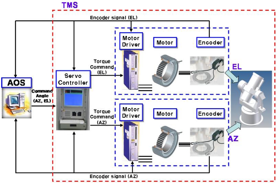
The driving control system is composed of the encoder and the interface to read the present angular position of the azimuth axis and the elevation axis, the servo controller to calculate the error between the present angular position and the target angular position and generate the control signals, the motor driver to generate the electric current provided to the motor based on the control signals, and the motor that actually drive the mount by the provided current. Fig. 7 shows the configuration of the driving control system of ARGO-M mount. ARGO operation system (AOS) delivers the angular position commands for the azimuth axis and the elevation axis to the servo controller. The servo controller, then, gives torque command to the motor driver of each axis to rotate the axis to the target angular position. The motor drivers supply electric current to the motors to rotate the axes. The angular information of the encoder fixed at the axis is transferred to three parts including the motor driver, the servo controller and the AOS.
3. EVALUATION OF THE DESIGN BY USING THE ARGO-M SIMULATOR
3.1 Design of the ARGO-M tracking mount simulator
Based on the previous preliminary design of the shape and axis-driving mechanism of the ARGO-M tracking mount, the simulator was designed and fabricated to evaluate the system accuracy and tracking accuracy of the elevation axis. The simulator focused on the verification of the mechanical mechanism design and the driving control performance of the elevation axis that moves under the weight load in the gravitational direction. The ultimate goal is to obtain the important design data for the detailed design of the mechanical system and controlling system of the tracking mount. Fig. 8 shows the designed simulator. The shape of the mount is identical to that of Fig. 1, but the azimuth axis was fixed, having the outer shape only, and the elevation axis was set to be rotated with degree of freedom. The total weight of the optical mechanical part was set to be 300 kg as presented in the design requirement. The core parts including the driving motor, the encoder and the bearing were the same with those selected in the preliminary design. An axial shape of variable moment instrument was installed at the tube body of the optical system to test the driving control performance when the tube body is moved up and down, varying the moment of inertia.
3.2 The tracking performance test of the ARGO-M tracking mount simulator
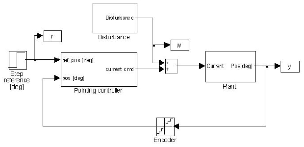
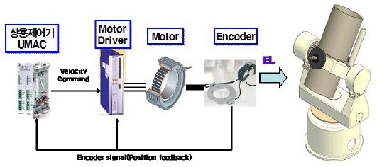
The simulator was fabricated to test the driving of the elevation axis only. UMAC, which is widely used for motion control, was applied as the controller for the driving test. UMAX, with 16 bit DAC and 24 bit counter, gives the control commander in 2.25 kHz frequency. The commercial controller controls only the elevation axis. Only one of each core part, such as the motor, the encoder and the motor driver is attached to drive the elevation axis. The positional information from the encoder is provided to both the commercial controller and the motor driver. The commercial controller generates the speed command to the motor driver in comparison with the positional information provided by the encoder so that the motor can rotate according to the positional trajectory of the motor that has been programmed in the memory. The motor driver is set to the speed mode and drives the motor receiving the speed command from the controller. The configuration of the driving control system for the simulation test is shown in Fig. 9 (Maneri & Gawronski 2000, Cho et al. 2003).
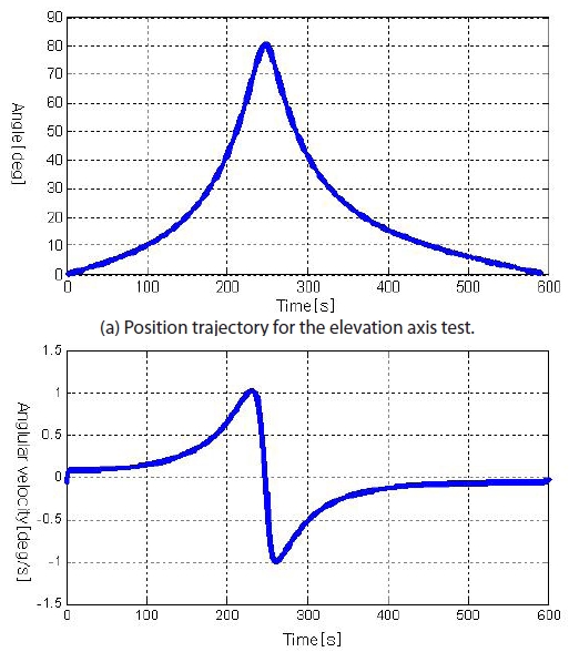
To verify the command-following performance of the simulator, the elevation axial trajectory of an actual satellite was entered as the positional trajectory information of the commercial controller and the tracking error generated when the commercial controller was tracking the entered positional trajectory was discussed. The positional trajectory used for the test was the elevation axis trajectory of ISS (International Space Station) that is shown in the reference (Kim & Min 2003). The altitude specifications of ISS are the average altitude of 373.7 km, the maximum altitude of 382.4 km and the minimum altitude of 365.0 km. Since ISS is the satellite at the lowest altitude in comparison with the altitude specification of the satellites tracked by ARGO-M, 300-25,000 km, and thus it covers the elevation axis rotational speed of the motor required to track a satellite from the lowest speed to the highest speed, it renders the advantage that the command-following performance of the simulator can be verified in a wide range of speed. Fig. 10 shows the position and speed trajectory used for the experiment. As shown in Fig. 10b, the maximum angular speed of the tracking motor was 1 deg/sec, approximately. For the actual experiment, the positional trajectory between 0-300 seconds out of the total 600 seconds in Fig. 10a was sampled with 20 msec time interval and entered to the commercial controller memory (Lee 2007).
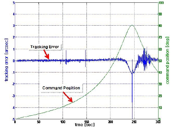
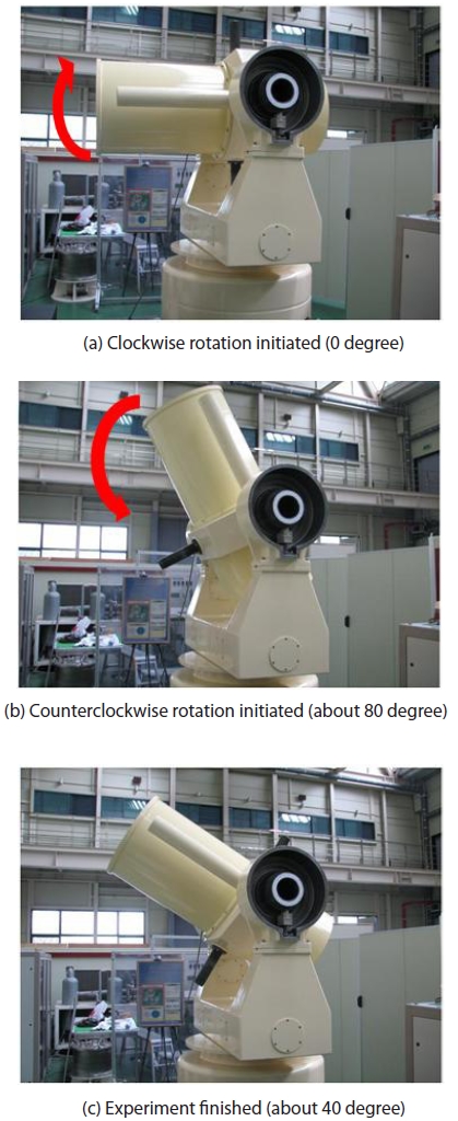
After the initiation of the tracking experiment with the input position trajectory, the driving axis motor rotated clockwise from the initial zero degree to about 80 degree, and then it rotated to about 40 degree position counterclockwise until the end of the experiment. The tube body position during the experiment is shown in Fig. 11. The input trajectory and the tracking error were collected by using the data logging function of the commercial controller and are shown in Fig. 12.
Although there was about 7 arcsec of tracking error at the part where the rotational direction of the motor was inverted, the 5 arcsec of pointing accuracy requirement was satisfied in other parts with the tracking error less than maximum 1 arcsec. The range where the directional inversion during the actual satellite tracking takes place, during the actual satellite tracking is the ceiling area. Since SLR stops the satellite tracking, within a certain angular range around the ceiling, the tracking error around this part is not very significant. Though the overall tracking error was small, less than 0.2 arcsec, the tracking error increased to 1 arcsec in the range between 250 seconds to 300 seconds when the tube body moves downwards. If the weight balance is perfect around the rotational axis of the elevation axis tube body, the tracking performance along with the rotational axis should remain the same. Although balancing the tube body weight was carried out in the simulator, the experimental results showed that it was not performed perfectly. The asymmetric up-and-down tracking performance seems to be resulted from the use of the minimum control algorithm for the simple tracking performance verification with the commercial controller, without perfect weight balancing and the analysis of the vibration through the structural analysis of the simulator. More stable tracking performance will be achieved by further balancing of the body tube weight and improving of the control algorithm.
3.3 Measurement of the system accuracy of the ARGO-M tracking mount simulator
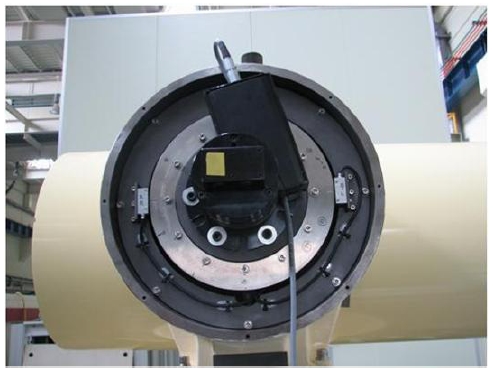
Since only the command-following performance of the system based on the encoder positional information could be evaluated by the previous tracking performance test of the simulator, the test was able to verify the performance of the controller and the core parts of the driving part used for the control. However, it could not be confirmed whether the tube body was able to point or track the desired absolute angle. Thus, additional test was required regarding how accurately the tube body could point the absolute angle. For this, the system accuracy was measured with a laser interferometer. The laser interferometer is the equipment measuring the motor rotation in absolute angle and it can evaluate the overall system accuracy including vibration of the mechanical part and bearing wobble as well as the controlling performance of the controller. The experiment can evaluate the system accuracy, the repeatability and the eccentricity compensation of the 2-head encoder.
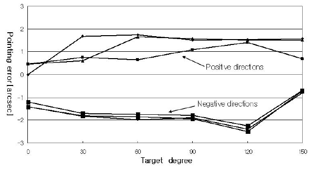
The measurement was conducted by commanding the tube body three times to point the positions in between 0 degree to 150 degree in 30 degrees of interval. Figs. 13 and 14 show that picture of the experiment that was conducted with the laser interferometer and the measurement results, respectively. The results showed that the repeatability was 0.9 arcsec for the (+)-direction movement and 0.2 arcsec for the (-)-direction movement. The overall system accuracy was 2.2 arcsec which satisfies the specification goal of 5 arcsec. About 3 arcsec of offset and repeated errors due to the hysteresis by the rotational direction inversion were found in the errors during the rotational direction inversion between (+)-direction rotation and (-)-direction rotation. These errors seemed to be removed by the addition of the compensation algorithm to the controller in the future. In this case, the system accuracy will be improved as the error will be reduced to less than 1 arcsec. Moreover, the analysis of the individual errors in the (+)-direction and the (-)-direction showed that the errors were small, less than 1 arcsec, in both direction without the error components by the eccentricity, indicating that the eccentricity compensation function of the 2-head encoder worked well.
In this study, for the preliminary design of the tracking mount for the movable ARGO-M SLR system, we have presented the selection of the technological specifications and the model through the technological consideration of the core parts, the mechanical structure shape design and the mechanism design of the axis driving part. In addition, we have designed and fabricated a simulator for the test of the elevation axis and presented the results, in order to comprehensively consider the suitability of the tracking mount core parts selected by the preliminary design, the validity of the axis driving mechanism designed in relation with those parts, and the validity of the configuration of the basic control system.
The driving control test results of the simulator verified that the repeatability and the tracking error of the tracking mount were maintained within the range of the pointing accuracy with a sufficient margin. Based on this, the evaluation was carried out for the performance of the core parts including the direct drive type motor, 2-head encoder and cross-roller bearing that had been selected in this study. Further, it was found that there was difference in the tracking performances due to the non-perfect weight balancing of the elevation axis tube body. It indicates that the effect of the weight balance around the rotational center can be the same to the azimuth axis. Efforts must be taken for the perfect balancing of the weight in the case of the actual manufacturing of the movable SLR. In addition, we have understood that there was room for improvement of the repetitive errors and hysteresis errors through the modification of the control algorithm.
We have the plan to find out potential problems by using the simulator, develop the control algorithm only for the system and carry out detailed design, supplementing the weak points of the present design. It is expected that the core design technology for the development of ARGO-M tracking mount can be obtained based on these research results, and the technology can be further utilized as the fundamental technology for the tracking mount design and the accurate driving control in the aerospace observation instruments including astronomical telescope as well as in the weapon system for the national defense.
This work was supported by the Korea Astronomy and Space Science Institute performing the space geodesy SLR project of the Ministry of Education, Science and Technology.