A fault tolerant satellite attitude control scheme with a modified iterative learning law is proposed for dealing with actuator faults. The actuator fault is modeled to reflect the degradation of actuation effectiveness, and the solar arrayinduced disturbance is considered as an external disturbance. To estimate the magnitudes of the actuator fault and the external disturbance, a modified iterative learning law using only the information associated with the state error is applied. Stability analysis is performed to obtain the gain matrices of the modified iterative learning law using the Lyapunov theorem. The proposed fault tolerant control scheme is applied to the rest-to-rest maneuver of a large satellite system, and numerical simulations are performed to verify the performance of the proposed scheme.
Thousands of satellites are now in operation for various purposes such as communication, navigation, military service, weather forecasting, and terrestrial and astronomical observations. Since satellite launches usually entail much cost and time, the social and economic cost that arises from satellite failure is critical. For satellite attitude control, reaction wheels, thrusters, and control momentum gyros are widely used as actuators. Therefore, the attitude control performance can be affected by actuator failure. If actuator failure occurs, the mission of the satellite cannot be accomplished or will be limited. Recently, the demand for satellite fault-tolerant control systems is increasing; therefore, considerable research has been undertaken that utilizes various control methods such as adaptive control, neural networks, sliding mode control, and so on (Henry, 2008; Jiang et al., 2008; Talebi and Patel, 2006; Tehrani et al., 2005; Wu and Saif, 2005). Tehrani used an estimator, based on neural networks, for fault diagnosis of the reaction wheel in a satellite attitude control system (Tehrani et al., 2005). Wu and Saif applied a sliding mode controller, based on neural networks, for satellite fault diagnosis (Wu and Saif, 2005). Henry used H-infinity and H_filter based schemes for the fault diagnosis of microscope satellite thrusters (Henry, 2008).
Several estimation and control schemes have been applied to deal with the failures of satellite systems. Especially, the iterative learning law is a fault estimation scheme for detecting and estimating faults. The iterative learning law using previous information can be applied to estimate both constant faults and time-varying faults (Chen and Saif, 2001, 2007).
In this paper, a fault tolerant control scheme with a modified iterative learning law is proposed to deal with the decreased effectiveness of satellite actuators. The modified iterative learning law using only information that is associated with the state error is adopted to estimate the influence of the actuator fault and the external disturbance. Lyapunov stability analysis is performed to obtain a stable controller. The performance of the proposed satellite attitude fault tolerant control scheme is verified by numerical simulations.
This paper is organized as follows. The second section describes the satellite system and the rest-to-rest maneuver of the satellite. In the third section, a fault tolerant controller with a modified iterative learning law is designed, and stability analysis is performed. In the fourth section, numerical simulations are performed to verify the performance of the proposed fault tolerant satellite control scheme. Finally, conclusions are drawn in the fifth section.
2. Satellite Dynamics and Mission
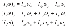
The satellite system considered in this paper is specified as follows (Chobotov, 1991).
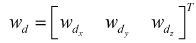
In the above,
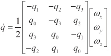
The quaternion vector
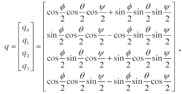
In Eq. (2), (
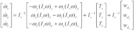
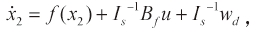
The dynamic equations of Eqs. (1) and (2) can be rewritten as follows.
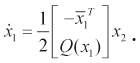
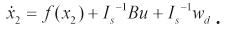
Here,

Note that
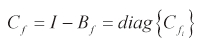
where the actuation effectiveness matrix,
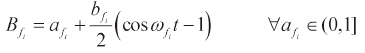
In Eq. (8),
The satellite usually performs various maneuvers such as rest-to-rest and despin. In this paper, the rest-to-rest maneuver is considered. The angle of maneuver of the principal axis of the satellite can be represented as follows.
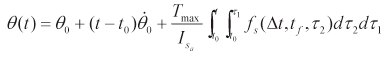
In Eq. (10),
For the rest-to-rest maneuver, the following boundary conditions should be satisfied.
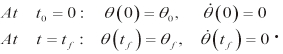
In Eq. (11), θf ? θ0 is the maneuver attitude angle,
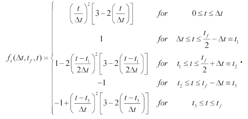
In Eq. (12), and the torque-shaping parameter, Δt=α
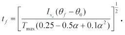
The target maneuver time,
Note that each axis's desired reference trajectory for the satellite rest-to-rest maneuver can be obtained by using Eqs. (10, 12, 13).
3. Fault Tolerant Control Scheme with a Modified Iterative Learning Law
In this section, a fault tolerant control scheme with a modified iterative learning law is designed to deal with the decrease in the effectiveness of the actuator and the external disturbance.
First, let us design the sliding mode controller to make the satellite attitude angles track the reference trajectory in Eq. (10) using the pseudo control input. Note that the state vector,
Using the quaternion vector and the desired trajectory, the sliding surface is defined as:
where the reference trajectory,

, is constructed to perform the rest-to-rest maneuver. Since the condition,
Differentiating Eq. (14) with respect to time yields:
where
To satisfy the reaching condition of the sliding surface, the following Lyapunov candidate function is considered.

Differentiating Eq. (16) with respect to time and substituting Eq. (15) into the resulting equation yields:
The pseudo control input vector for the attitude angle can be obtained by the sliding mode control method as:
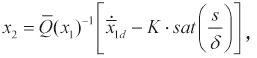
where
The pseudo control input of Eq. (18) is used as the reference trajectory of the angular rate,
Substituting Eq. (18) into Eq. (17) gives:
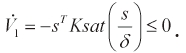
Finally, it is concluded that the stability of the reference trajectory tracking controller is guaranteed.
Now, let us design a fault tolerant control scheme to deal with the decrease in effectiveness of the actuator and the external disturbance. Using the reference angular rate trajectory,
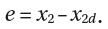
Differentiating Eq. (20) with respect to time yields:
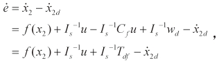
where
Let us select the fault tolerant control input using Eq. (21) as:
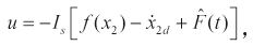
where (F^) is the estimated fault signal that can be obtained using the modified iterative learning law to compensate the influence of the actuator fault and the external disturbance. Usually, faults that occur in the system are unknown. To deal with this problem, the modified iterative learning law is used.
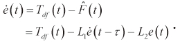
The general iterative learning law is updated by both the previous information and the state estimation error (Chen and Saif, 2001, 2007). Note that the modified iterative learning law proposed in this paper is updated using only the information associated with the state error; therefore, the influence of the actuator fault and the external disturbance can be estimated as follows:
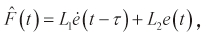
where the parameter, τ, is an updating interval.
The gain matrices,
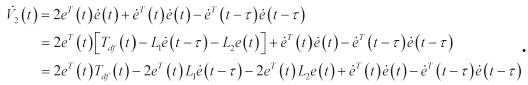
Let us consider the following Lyapunov candidate function.
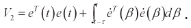
Differentiating Eq. (25) with respect to time and substituting Eq. (24) into the resulting equation yield:
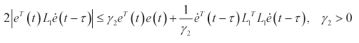
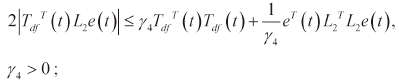
The following inequalities can be obtained (Yan et al., 1998).

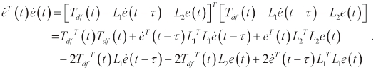
The following equation also can be obtained using Eq. (24).
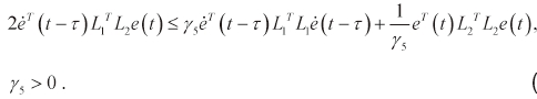
Similarly, the following inequalities can be obtained:
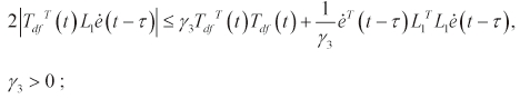
and
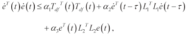
As a result, the inequality, Eq. (29), can be obtained using Eqs. (30-32) as follows:
where

and
By assuming

and
, the following can be derived:
where
By substituting Eqs. (27, 28, 33, 34) into Eq. (26), the following equation can be obtained.
To satisfy Lyapunov stability, the following relation should be satisfied for the gain matrices,
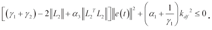
From the above equation, the following inequality is obtained for using the gain matrix,
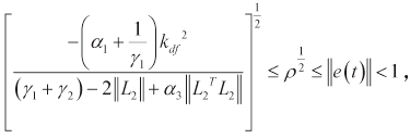
where
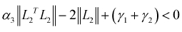
Therefore, the gain matrix,
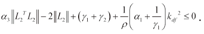
In summary, the gain matrices,
Remark: The state error can be used for fault monitoring purposes. When there are no faults in the system, the state error should be zero or close to zero. On the other hand, an increase in the state error would point to the occurrence of a fault. After the fault occurs, the estimated fault signal would learn about the fault and the state error will again be driven to zero or a value close to zero. This means that the iterative learning law can learn and update by the previous and the present state error information.
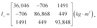
Numerical simulation has been performed to verify the proposed fault tolerant control scheme. The Hubble space telescope is considered as the satellite system (Thienel and Sanner, 2007; Wie et al., 1993). The inertia,
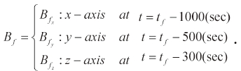
With regard to the external disturbance, the disturbance that is induced by the solar array is considered as follows (Wie et al., 1993).

The attitude (quaternion) reference trajectory is for the rest-to-rest maneuver. The maximum value of the available torque,
4.1 Case 1 ? Sequential Occurrence of Actuator Faults
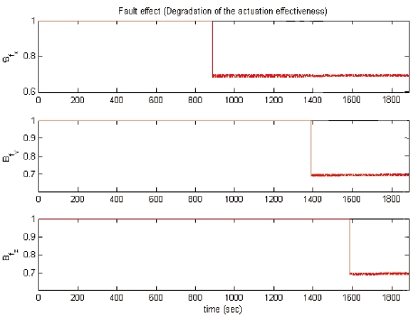
In this case, the actuator faults are considered as follows.
In Eq. (8), the magnitude of the actuation effectiveness with regard to the actuator fault is chosen as 0.7,
The gain matrix is chosen as
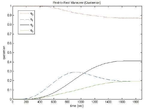
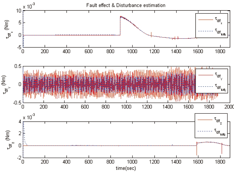
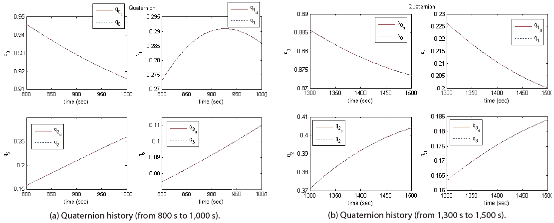
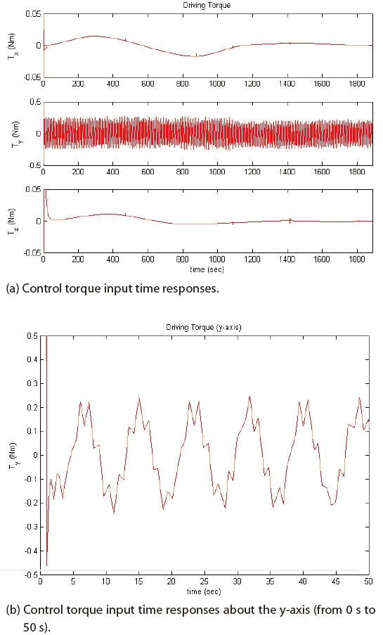
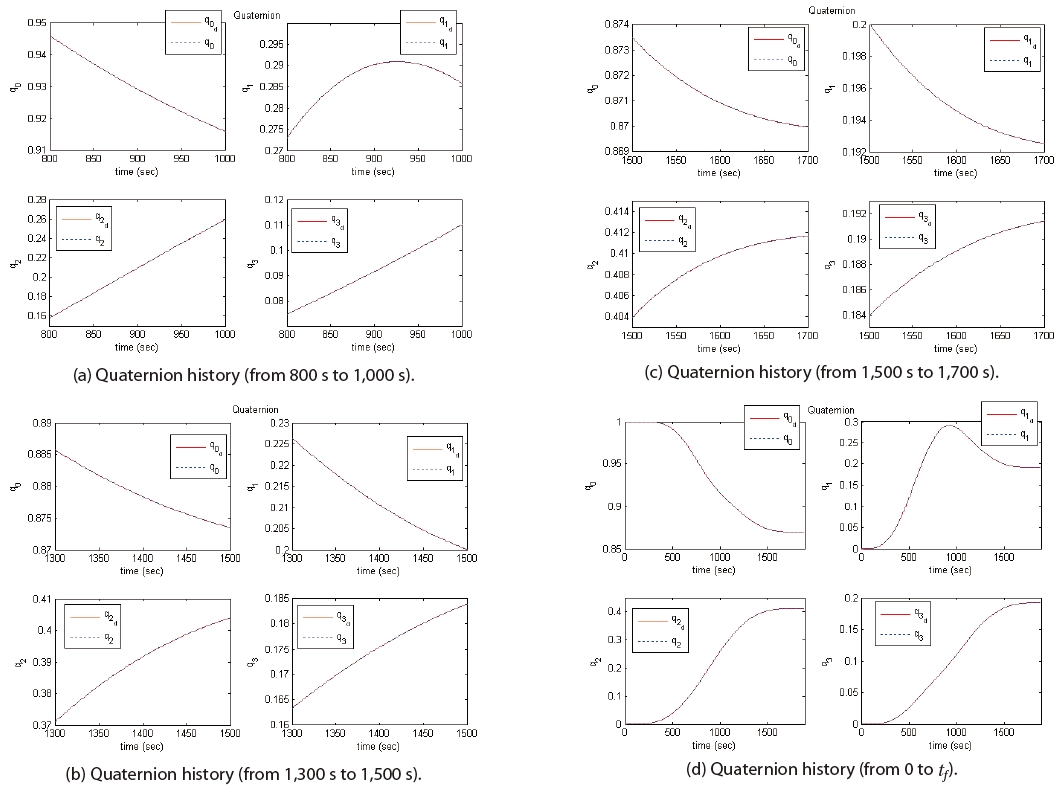
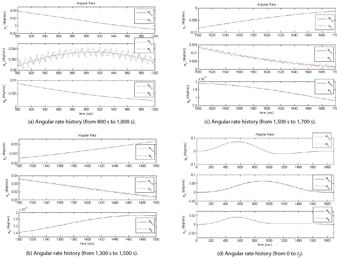
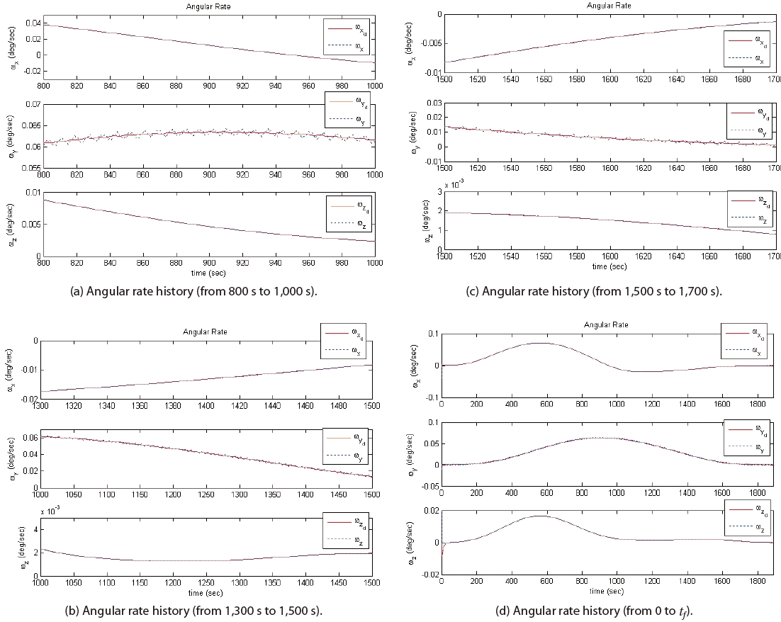
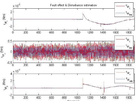
The simulation results are shown in Figs. 3-6. It can be seen from Figs. 3 and 4 that the state values, after the occurrence of the actuator faults, follow the reference trajectories very well. Figure 5 shows that the actuator faults can be estimated by the modified iterative learning law. As shown in Fig. 6, a high-frequency control torque input is used for the y-axis. The control torque input response of the y-axis, from 0 to 50 seconds, is shown in Fig. 6(b); it can be seen that a high-frequency control input is required to deal with the disturbance that is induced by the solar array. As seen in the simulation results, the fault tolerant control scheme with the modified iterative learning law deals with the actuator faults and the external disturbance.
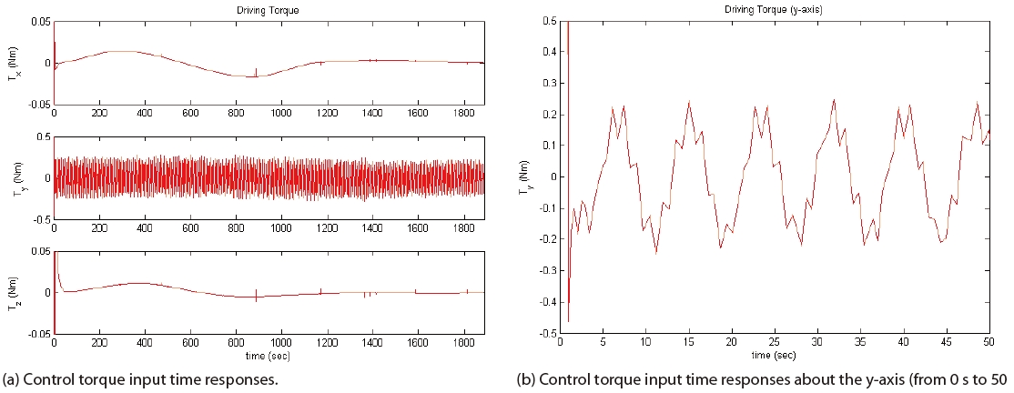
4.2 Case 2 - Simultaneous Occurrence of Actuator Faults
In the second case, numerical simulation is performed for actuator faults that occur at same time. The actuator faults are considered to occur at
A satellite attitude control scheme is proposed to deal with actuator faults and external disturbances. The reference attitude angle of the satellite is designed using a near minimum-time maneuver in the rest-to-rest maneuver. A fault tolerant control scheme for the satellite attitude system with a modified iterative learning law is proposed to deal with the degradation of the actuation effectiveness and the external disturbance due to the vibration of the solar array. The modified iterative learning law is considered to estimate the unknown influence of the actuator fault and the external disturbance. Note that only information that is related to the state error is used. The fault tolerant control scheme is applied to a large satellite system, and the performance of the proposed satellite attitude control scheme is verified by numerical simulation. The proposed algorithm can be applied in an attitude control system to improve the reliability of satellite systems.