In recent years, there has been a growing interest in a small-sized unmanned aerial vehicle (UAV) in both civilian and military applications. In particular, new concepts of rotorcraft UAVs such as ring-wing (Johnson and Turbe, 2005) and multi-rotor types (Escareno et al., 2008; Romero et al., 2007), have been studied because of their capabilities of vertical takeoff and landing, which can be used in small-area monitoring, building exploration, surveillance and rescue mission. Since the rotorcraft UAV is dynamically unstable, suitable control strategies required for stabilization have been developed (Bouabdallah and Siegwart, 2005; Fowers et al., 2007). Since the aerodynamics of a rotorcraft UAV is difficult to describe accurately, it is important to verify the performance of the control system by flight tests. Normally, most autonomous flight tests are performed outdoors and reliable navigation systems like the global positioning system (GPS) is used. Several outdoor experimental test-beds have been developed for rotorcraft UAVs (Hoffmann et al., 2007; Johnson and Schrage, 2003; Shim et al., 2000).
However, outdoor test-bed requires not only wide area, suitable transportation and qualified personnel but also tends to be vulnerable to adverse weather conditions. Accordingly, an indoor flight test-bed using a vision system is emerging as a possible solution to overcome these outdoor limitations and to perform more efficient and easier flight experiments. The indoor flight test-bed enables flight tests that are protected from environmental conditions. Furthermore, it requires no other on-board sensors like GPS or inertial navigation system (INS) since the pose information can be directly obtained by image processing. Recent work on the indoor test-bed using a vision system has been carried out by the Massachusetts Institute of Technology (MIT) Aerospace Control Lab in the development of the RAVEN system (Valenti et al., 2007). The RAVEN system estimates the information of the UAV by measuring the position of the reflective maker installed in the UAV via a beacon sensor used in motion capture. Also, a visual control system for a micro helicopter has been developed in (Yoshihata et al., 2007). Two stationary and upward-looking cameras placed on the ground track four black balls attached to the helicopter. The errors between the positions of the tracked balls and pre-specified references are used to compute the visual feedback control input.
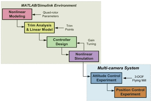
In this paper, we propose an experimental framework that considers the characteristics of the rotorcraft UAV for the design and validation of a control system by applying the indoor test-bed concept using a vision system. The development of the rotorcraft UAV control system begins with nonlinear modeling of the vehicle followed by controller design using numerical simulation and concludes with a flight test. Our experimental framework carries out the development procedure systematically for the manufactured quad-rotor UAV by using the 3-degree of freedom (DOF) flying mill as a setup for the attitude control and multi-camera system. The proposed framework can be applied to various types of rotorcraft UAVs with minimum personnel at low cost in a short period of time. In addition, because the position or velocity control is performed after sufficient performance of the attitude control, which is the inner-loop of the control system, has been ensured, the designed controller can be tested effectively and safely. This paper is organized as follows. An overview of the structure and facility of our experimental framework is provided in Section 2. Section 3 gives a brief explanation of the mathematical modeling of the quad-rotor UAV, followed by the description of the controller design procedure using the proposed experimental framework. Finally, Section 4 introduces the implemented multi-camera system and shows the experimental results of the quad-rotor UAV control.
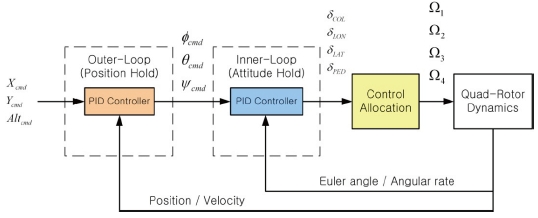
In this section, the proposed experimental framework for controller design of the rotorcraft UAV is presented. In the overall control design procedure, the experiment step is separated into two parts: one is the attitude control experiment, and the other is the position control experiment, as shown in Fig. 1. The attitude control experiment is carried out to verify the individual performances of the controller, since they are important in the entire control performance of a multi-rotor type rotorcraft UAV, which has no swash-plate mechanism. Also, a vision system with commercial available chargecoupled device (CCD) cameras was developed to carry out indoor flight tests for the position control experiment. This system provides full 6-DOF navigation information with high accuracy without the need for any other expensive sensors. Communications between the onboard microcontrollers and the ground computer system enables the monitoring and online tuning tasks of parameters in the embedded controller. In the overall control design procedure, steps from nonlinear modeling to nonlinear simulation were developed in the MATLAB/Simulink environment, as shown in Fig. 1. In the following subsections, the details of the experimental framework which includes the manufactured quad-rotor UAV, the 3-DOF flying mill, and the multi-camera system are explained.
The quad-rotor UAV used in experiments currently consists of four outrunner brushless dc motors, commercially available off-the-shelf rotors, two micro-controllers, a 5-channel receiver, and an attitude heading reference system (AHRS) as shown in Fig. 2. The size of the UAV is approximately 0.8 meter by 0.8 meter, fitted by four brushless dc motors, which are geared to each rotor without a gearbox. The vehicle can lift around 300 grams of payload and hover for about 10 minutes with 11.1 V/4,200 mA LiPo battery. The airframe was designed by several iterations. The final airframe is equipped with protective shrouds made of carbon fiber tubes to protect the rotors against other objects. It was designed with aerodynamic considerations since it was found that airflow disruption by protective shrouds affects yaw control performance in (Hoffmann et al., 2007).
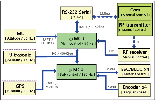
The real-time electronics architecture shown in Fig. 3 consists of control, sensor, and actuator parts. The control part, which has two AVR microcontrollers, generates control signals according to given control laws and manages communications between the sensor and actuator parts. The main microcontroller unit (MCU) computes the commands of the angular velocities of four rotors, while the sub MCU generates the pulse width modulation (PWM) signals for the control of brushless direct current (BLDC) motors. Microcontrollers are implemented with two time scales, and the sampling frequency of the sub-microcontroller is twice as fast as that of the main-controller since it requires faster response. The onboard sensor part includes the MicroStrain 3DM-GX1 attitude heading reference system (AHRS) and four encoders. The AHRS, which is mounted on elastic bands to prevent transmission of high frequency vibrations, combines three angular rate gyros with three orthogonal accelerometers and three orthogonal magnetometers to output the orientation of the vehicle at 70 Hz. The rotor angular velocities are obtained from four optical encoders. These measurements are sent to the microcontroller and ground station via the RS-232 interface at the maximum rate of 115.2 kbps and directly used without any filtering. In the actuator part, four electronic speed controllers receive the PWM signal from the sub-microcontroller. The control laws in microcontrollers can operate in different modes by using measured from the sensors or received information from the ground computer. The control laws in different modes allow us to tune or change the structure of the controller efficiently during flight experiments.
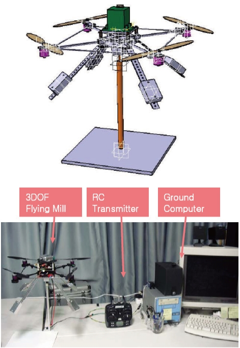
The 3-DOF flying mill shown as Fig. 4 is designed to implement and tune the attitude controller. To experiment the attitude controller safely, we employ a spherical joint and aluminum pipes. This flying mill gives the vehicle unrestricted yaw motion and about 45 degrees of pitch and roll motions, while restricting the vehicle to a fixed position in three-dimensional space.
To improve the validity of the experimental results, the 3-DOF flying mill was developed with consideration of some factors. First, the ground effect due to the four rotors at low altitude was solved by placing the 3-DOF flying mill 0.7 meters above the ground. Second, additional four mass balancers were built to match the centers of spherical joint and the vehicle, as shown in Fig. 4. The positions of these balancers were determined by estimating the moment of inertia using the CATIA program. Finally, we employed a low friction spherical joint to reduce its influence on the stability of rotational dynamics. With these considerations, 3-DOF flying mill could be used with acceptable level of validity, although some uncertainties still remained in the attitude control experiment.
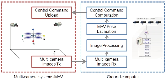
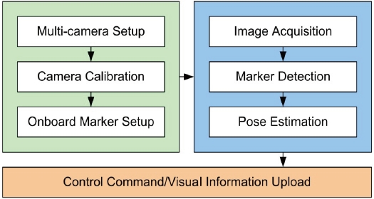
The multi-camera system focused on providing accurate navigation information for an autonomous flight of an indoor UAV. As shown in Fig. 5, the system consists of four major components: the multi-camera, the ground computer, the onboard color marker, and the quad-rotor UAV. In the design of the multi-camera system, the numbers of camera and marker are important factors. In most cases, three markers detected by one the camera can be used to determine the position and attitude of the vehicle as the rank of error covariance is checked. If there is a sign ambiguity or the endpoints of the marker position vectors are connected by a straight line, four or more markers are required (Sun and Crassidis, 2002). As the number of camera and marker increases, the performance of the system, such as accuracy and robustness, is enhanced, although the computation burden becomes heavier. In this paper, our system is composed of two cameras and four markers attached to the UAV, which guarantee observability and reasonable performance.
3. Quad-Rotor UAV Modeling and Controller Design
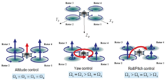
In this section, we introduce the operation concept of the quad-rotor UAV, which is selected as the test-bed vehicle, and derive its mathematical model. In addition, the procedure applying our experimental framework to the control system design is explained.
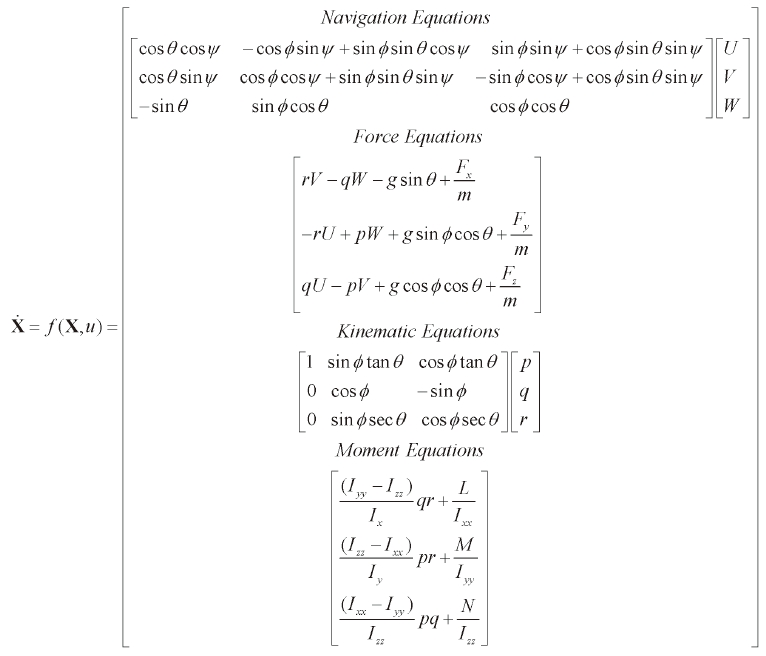
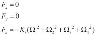
For the quad-rotor UAV control, the flat-Earth, body axes six-degrees-of-freedom equations are used as the rigid-body equation of motion given by (Stevens and Lewis, 1992): where Fx, Fy, Fz are the external forces and L, M, N are the external moments acting on the center of gravity with respect to body-fixed frame. In the quad-rotor UAV, the external forces and moments are generated by the aerodynamic forces of the four rotors. Under the assumption that the aerodynamic coefficients of the rotors are constant, the external forces and moments are obtained as follows (Bouabdallah et al., 2004). First, the thrust generated by the rotor i is written as:
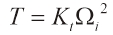
where Kt is the thrust coefficient and Ω denotes the angular velocity of the rotor. Since the thrust acts on the z-axis only, the external forces are given by:
The reactive torque generated by the rotor i due to rotor drag is given by:
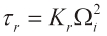
where Kr is the torque coefficient. Then, the airframe torque generated by the rotors is given by:

where d is the distance from the rotors to the center of mass of the quad-rotor. The gyroscopic toques due to the combination of the rotations of the airframe and the four rotors are given by:
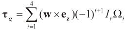
where ez = [0, 0, 1]T denotes the unit vector, w is the angular velocity vector of the airframe expressed in the body frame, and w = [

An actuator in the quad-rotor control system is the DC motor. It is possible to model the dynamics of a DC motor system as a first order system (Franklin et al., 2002) and its transfer function is given by:
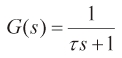
where τ is the time constant of the motor dynamics.
The nonlinear quad-rotor UAV model is linearized at hover trim conditions for stability analysis. In the hover condition, the state-space forms of the longitudinal and lateral dynamics are represented by Eqs. (9) and (10).
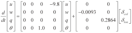
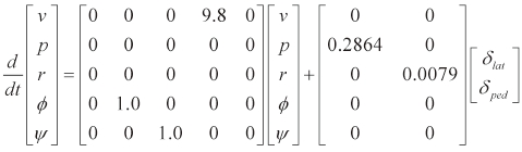
Since the rotor aerodynamics is linearly related to the square of the angular speed of the rotor as given in Eq. (2), the dynamics of the quad-rotor UAV can be described as a double integrator type. Thus, the Eigen-values for the openloop system dynamics of the quad-rotor UAV in the hover condition are all zero, which means that the quad-rotor UAV is neutrally stable.
The entire architecture of the quad-rotor UAV control used in this paper is shown in Fig. 8. In the inner loop, Euler angles and angular velocities are fed back to the attitude hold autopilot. In the outer loop, position and velocities are fed back to the position hold autopilot.
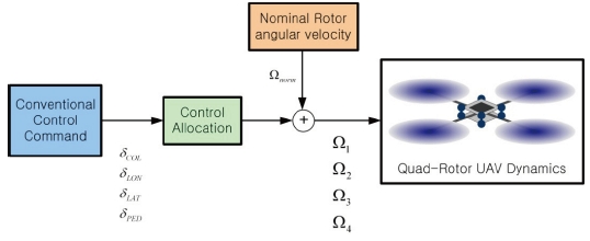
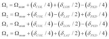
Four control channel commands generated by the controller are transformed into the angular velocity of each rotor by using control allocation method as given in Eq. (11) and Fig. 9.
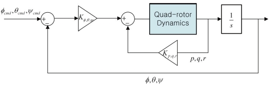
The attitude hold autopilot is designed to track and hold the pitch, roll and yaw angles. It consists of an inner-loop with an angular rate feedback and an outer loop with the Euler angles feedback based on the proportional-derivative (PD) control concept. The block diagram of the attitude hold autopilot is shown in Fig. 10. The control system derived so far can be validated by using the 3-DOF flying mill without a flight test. Since the quad-rotor UAV flies normally in near hover condition at low forward velocity, nominal angular velocities of rotors are set to the value of hovering flight condition during 3-DOF flying mill experiments.
Position hold autopilot is achieved by the pitch and roll attitude control, respectively. Control law for the position hold autopilot is given by:
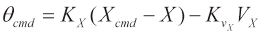
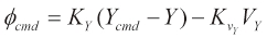
Altitude hold is achieved by the collective control input directly.
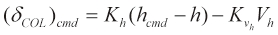
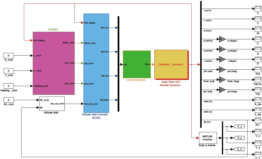
Figure 11 shows the MATLAB/Simulink block diagram of the developed quad-rotor UAV controller. This block diagram is used for the nonlinear simulation before the implementation of the controller and flight test.
As explained, necessary navigation information for position hold autopilot is obtained by the multi-camera system, and is transmitted to the onboard microcontroller of the quad-rotor UAV. When a flight test is performed in indoors, the quad-rotor UAV should be located such that it is within the coverage of the multi-camera system. According to the characteristics of the vehicle, the coverage can be controlled properly by changing either the number of cameras or the field of view (FOV) by camera placement.
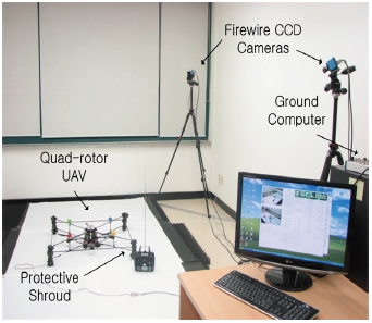
This section presents the experimental setups, and the attitude and position control results of the quad-rotor UAV with the proposed framework. Experimental testing was performed by using the multi-camera system called multiagent test-bed for real-time indoor experiment (MATRIX). Its configuration and specifications are illustrated in Fig. 12 and Table 1. Compared to the other vision systems, MATRIX system requires only a normal CCD camera, a computer and an inexpensive triggering board, so it can be easily implemented at low cost.
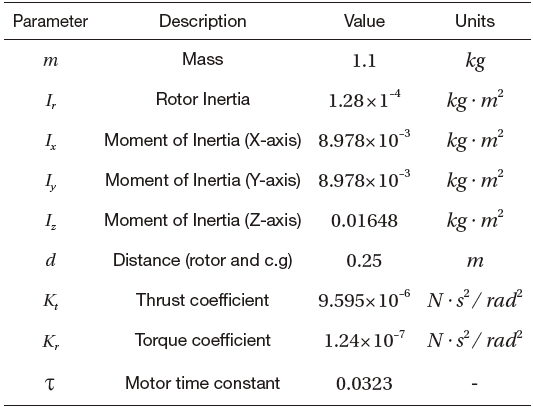
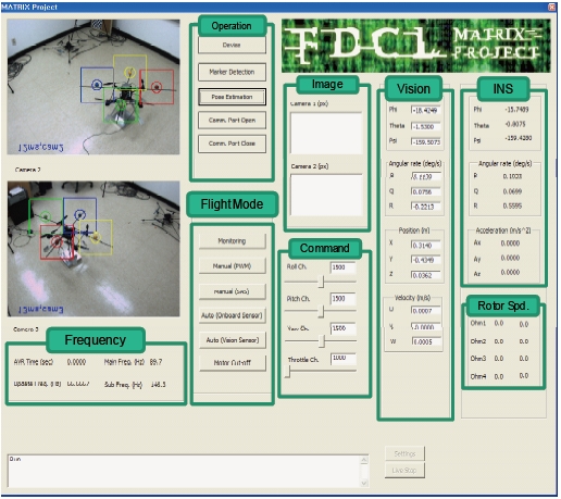
As shown in Fig. 13, the ground control system is designed to check the image data from the CCD cameras, the image processing time, the marker detection performance, the rotor speed, the AHRS data, the control system parameters and the pose estimation results. The physical parameters of our experimental quad-rotor UAV are given in Table 2.
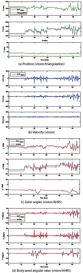
Before the control experiment, the performance of the MATRIX system is verified. Figure 14 shows the pose estimation results obtained from EKF, the position estimation by the linear triangulation method, and the AHRS measurement data at ±2.0&;ltamp;gt; accuracy. The quad-rotor UAV is controlled manually on the 3-DOF flying mill during the estimation. There were no misdetections while the four color markers existed in FOV of the multi-camera system.
[Table 1.] MATRIX specification
MATRIX specification
[Table 2.] Quad-rotor UAV parameter

Quad-rotor UAV parameter

Bias error
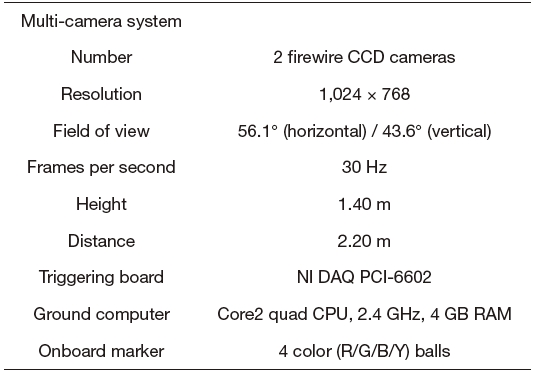
Processing time
[Table 5.] Control gains for the attitude(-) hold autopilot
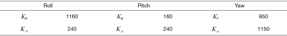
Control gains for the attitude(-) hold autopilot
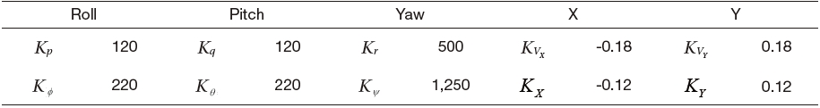
[Table 6.] Control gains for the position hold autopilot

Control gains for the position hold autopilot
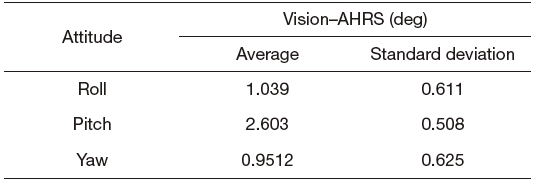
Figure 14(c) shows a bias error between the estimated value and the AHRS data, and Table 3 shows the average and standard deviations of this error. The bias error is mainly generated from the calibration error of the camera, and it can be decreased by a precise calibration procedure.
Furthermore, the time delay caused by image processing and data communication is represented in Table 4. We reduced the effect of the time delay by using a modified EKF, considering the delayed measurement as mentioned in Section 2.3.
From the above results, it is verified that the MATRIX system we implemented has reasonable performance, which can be used to control the quad-rotor UAV.
Figure 15 shows the experiment results of the attitude stabilization (Φ=θ=ψ=0˚) by the 3-DOF flying mill. For attitude control, we use Euler angles obtained from MATRIX system and angular rates from AHRS. The controller is designed based on the PD control concept, explained in Section 3.2. In general, control gains designed in the MATLAB/Simulink environment was very successful. However, experimental gain tuning improved the performance and stability of the controller because the dynamics and uncertainties were not modeled? Final control gains obtained by a number of flight experiments are as given in Table 5.
The position control is performed by using the position,
velocity and attitude information obtained from the MATRIX system and the angular rates from AHRS. Control gains are shown in Table 6. Due to the effect of three-DOF flying mill, such as ball bearing friction and balance mass bar inertia, the values of roll, pitch and yaw channels were a little different from those of Table 5, although they were of same order of magnitude. Accordingly, we can conclude that the experiment on the 3-DOF flying mill describes the real flight test properly within an acceptable error bound.
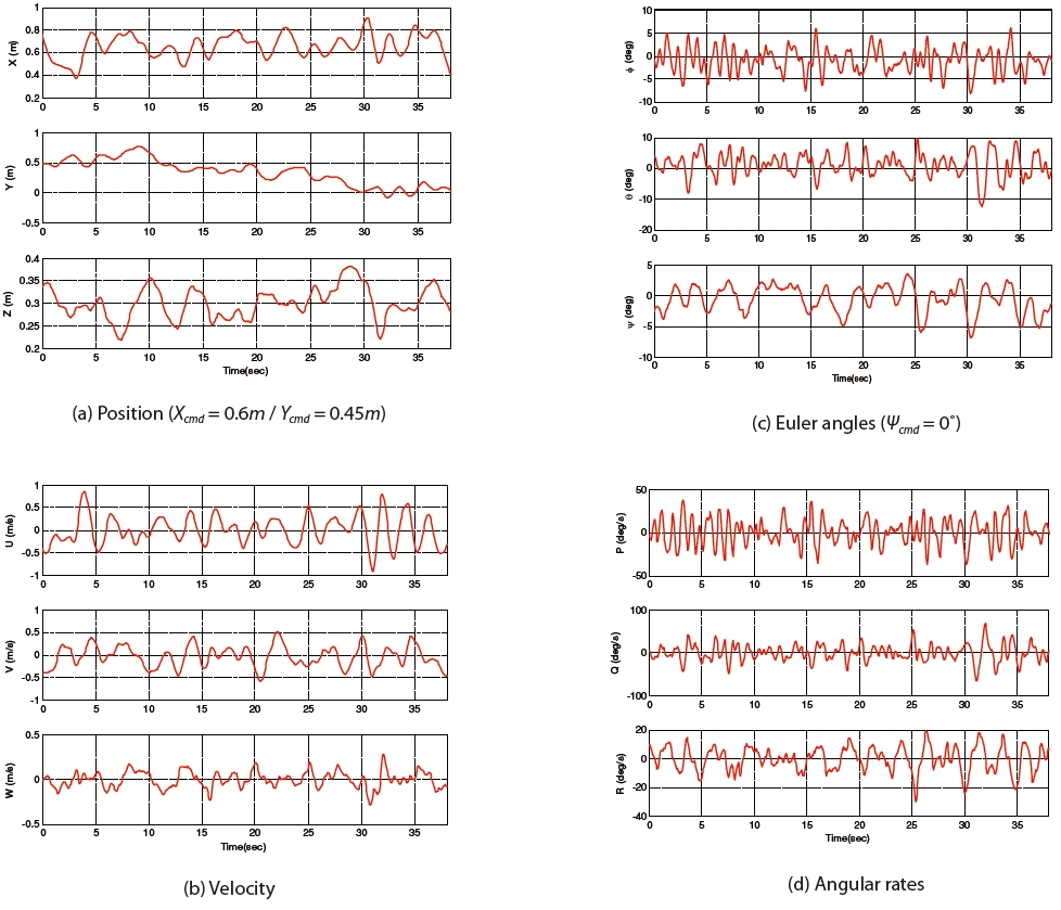
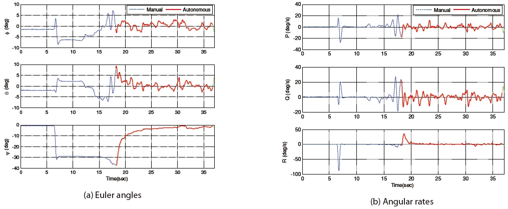
Figure 16 shows that the flight test results of the position and heading control without altitude control (i.e. fixed throttle). The mean and standard deviations for tracking error between commands and states are 0.056 m and 0.106 m for x, ?0.115 m and 0.215 m for y and ?0.577℃ and 2.210℃ for the heading angle, respectively. From the experiment result of attitude stabilization and position control, we can conclude that the proposed experimental framework and the implemented MATRIX system can be successfully applied in the development of the controller and in the flight test of the quad-rotor UAV.
The controller design for a rotorcraft UAV can be achieved by the experimental framework proposed in this paper by using a multi-camera system. The proposed experimental framework provides full 6-DOF navigation information with high accuracy and communications between the onboard and the ground computer system for the realization of an efficient controller design procedure. This system is built with low cost cameras and can operate in the indoor environment. In addition, damages due to the crashing of the UAV can be minimized since the flight test is performed after the performance of the attitude controller on the 3-DOF flying mill has been validated. The experimental results showed that the proposed approach has been applied to the controller design and implementation for the quad-rotor UAV successfully. Lastly, this system shows much potential in the development of various types of rotorcraft UAVs and control methods without the need for further modification.