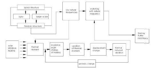
Space environmental tests of orbiting earthsatellite at developmental stage, have become veryimportant because of variety of complex activities thesatellite needs to perform for precise target requirements.In space environment without gravity or with very smallgravity, it is desirable to have lightweight space craftstructure having high flexibility with low frequency anddamping characteristic. The thermally-induced bendingmoment of the flexible structure by sunlight heatingproduces initial thermal deflection, accompanied byfluctuating moment due to periodic changes of sunlightincidence angle, causing oscillation. Therefore thespacecraft structure can be vibrated due to this periodicchange of thermally-induced moment[1,2,3].
If the frequency of the thermally-inducedvibration becomes the same as natural frequency, theresonance phenomenon appears. This resonancegives rise to various structural failure problems.Figure 1 shows a conceptual view of the mechanismof the thermally- induced vibration of the spacecraftstructure in space environment. Solar panels or boomstructures for global position measurement aregenerally thin and flexible. Many works of flexiblestructure have been studied[4,5,6]. The simplifiedthermal environment of a thin flexible tube boom issimulated for this study. Because thermalenvironment of the earth satellite is changed alongwith the flight path, the experimental tests simulatevarious thermal environmental conditions by acontrollable heating lamp in vacuum chamber.
Design and Manufacturing of Experimental Test Equipment
>
Vacuum environmental condition test system
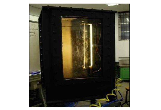
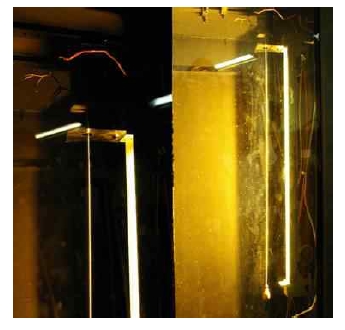
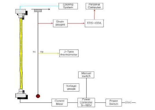
Figure 2 shows the thermally-induced vibratory simulation system of the flexible boom in atmospheric condition. Figure 3 shows the thermally-induced vibration simulation system of the flexible boom in vacuum condition which is to provide simulated space environments.
The heating lamp capacity in vacuum chamber ismaximum 2.5 kW class at 480 V. The lamp is located at80mm apart from the boom, and radiation of the lampheats up the boom surface. The concentrated tip mass of50g is attached at the end of the boom. A strain gage,which is the 120 ohm-FLA-5-23-1L of Tokyo SokkiKenkyuju Co .is attached on the surface positioned at20mm from the fixed end of boom specimen[7,8].
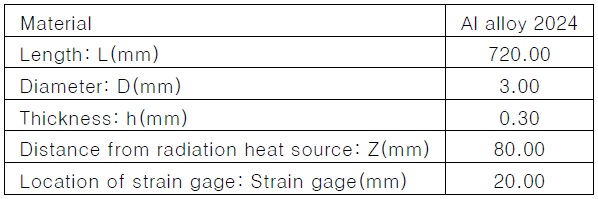
The specification of test specimen waspresented in Table 1. In order to protect the straingage from the direct heating, a protection cover isprovided shown as Figure 4. The x-directionalstrain is measured at 100 Hz using dynamic straindata recorder EDS-400A of KYOWA. Vacuum ismeasured by the VPRHS-OS-760 torr-4C sensor.The chamber is vacuumed to maximum 36 torrusing the 16VP-direct drive rotary vacuum pump(0.4kW, 4pole) of HITACHICO.
In order to protect the 2.5kW heating lamp fromoverheating, the lamp is cooled by cold water, and theinternal surfaces of the vacuum chamber are paintedby special heat protection paint, QT604 (L)-1999(black color), to reduce the deflected light.Furthermore the sight window with two sheets of the19mm thickness strengthening glass is mounted on thevacuum chamber with supporting mounts and sealants.
[Table 1.] Specification of test specimen

Specification of test specimen
Thermal environmental conditions can beadjusted by various voltage changes such as 120V,240V and 440V, and variation of fluctuatingcharacteristic times is measured. After measuringvibratory fluctuating characteristics, heating isstopped just before the boom tip mass hits thelamp, and then the damping characteristics areinvestigated. Here fluctuating characteristic timedefines as the time between starting of oscillationand hitting to the lamp. Furthermore thermalenvironmental conditions are adjusted bycontrolling the lamp power. In order to keepaccuracy, three tests per condition are carried out.Natural frequencies are obtained experimental databy FFT analyzer using MATLAB program.
>
Experimental results and discussion
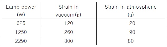
In both vacuum (36 torr) and atmospheric (753torr) conditions, natural frequencies, initial thermal strainsand vibratory fluctuating characteristic time of the boomare measured. The measuring results are compared atperiodic changes of thermal environmental conditions.Table 2 shows initial thermal strains at differentthermal environmental conditions with 625W, 1250Wand 2290W of lamp power in vacuum and atmosphere.As shown in the Table 2, the thermal strains at 625Wof lamp power are same in both vacuum andatmospheric conditions, but thermal strains in vacuumat higher lamp powers increase and the strains inatmosphere at higher lamp powers decrease inversely.It may be considered that the reduced temperaturedifference ratio between front and back surfaces byconvection in air reduces the thermally-inducedbending moment.

Initial thermal strains at different thermal environmental conditions in vacuum and atmosphere

Vibration fluctuating characteristic at different thermal environmental conditions in vacuum and atmosphere
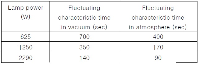
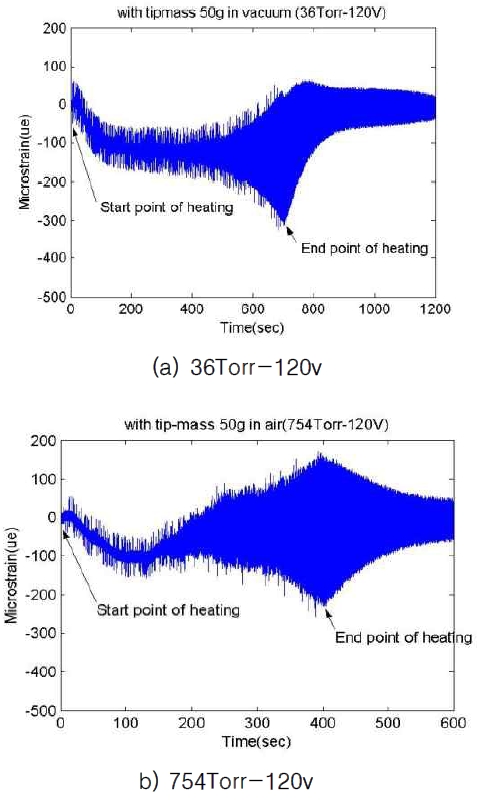
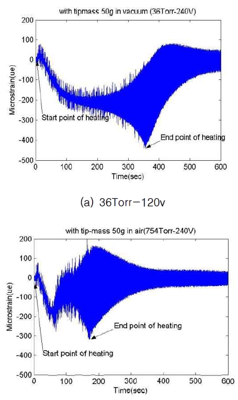
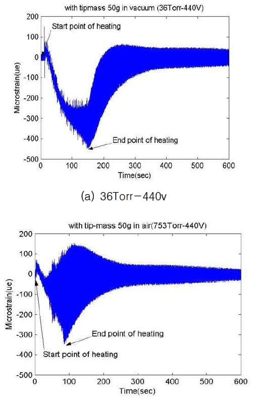
Table 3shows vibration fluctuating characteristic times at different conditions with 3 lamp power cases in vacuum and atmosphere. Vibration fluctuating characteristic time at both vacuum and air decreases with increases of lamp power. However the fluctuating characteristic times in atmosphere are much faster than those in
vacuum. It may be assumed that the second modenatural frequencies in air can accelerate rapidly thefluctuating characteristic phenomena. Figure 5, 6and 7 show experimental test results at differentthermal environmental conditions such as 625W,1250W and 2290W of lamp power in vacuum andatmosphere, which are previously explained atTable 2 and 3. As shown in figures, it is found thatthe overall thermally-induced vibration patterns atboth vacuum and atmospheric conditions areclearly different, however vibration fluctuatingcharacteristic patterns are almost same in spite ofdifferent lamp power conditions except for thefluctuating characteristic time.
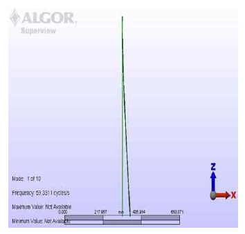
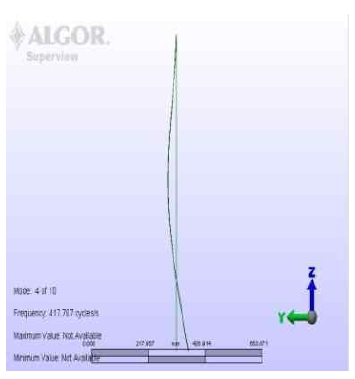
In this study, modal analysis of the thermally-induced vibration is performed by the finite element method. The FEM model uses 6481 shell elements with 50g tip mass and one end fixed boundary condition.[9] And a linear temperature distribution from front face (255℃) to back face (205℃) of the boom tube is assumed. Figure 8 and 9 show modal analysis results for the first and second flap modes and their natural frequencies.
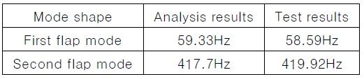
[Table 4.] Comparison between measured and predicted natural frequencies

Comparison between measured and predicted natural frequencies
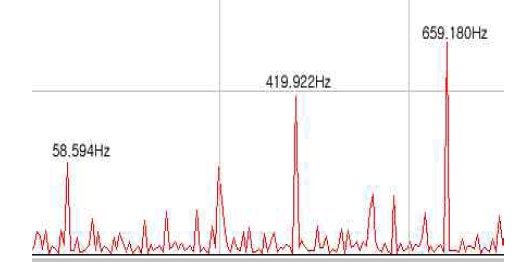
Table 4 shows natural frequencies of the thermallyinduced vibration of the boom at thermal environmental condition as 290W of lamp power in vacuum condition. Here experimental natural frequencies are obtained by FFT analyzer using measured thermal strains shown as Figure10. Table 4 shows that the analysis values are in good agreement with the measured values. And it was found that the thermal flutters in both vacuum and atmosphere have all the first flap mode shapes, but the flutter mode in air combines with the 2nd flapmode.
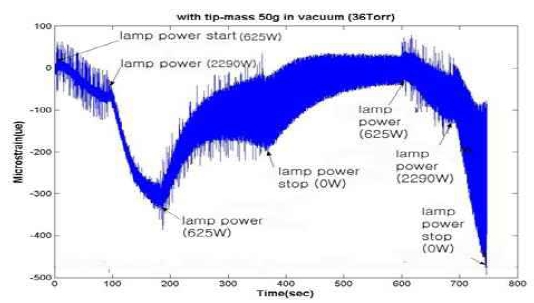
In order to simulate the flight condition ofthe orbiting earth orbit satellite, thermalenvironmental conditions are generated with thelamp power control followed by the input voltagesetting sequence such as 0V-120V-440V-120V-0V-120V-440V-0V shown in Figure 11. Asshown in figures, when the thermal strainapproaches to maximum at 625W of the lamppower, then the lamp power increases to 2290W.
After reaching to maximum strain at 2290W, thethermally-induced vibration is generated. However, ifthe lamp power decreases to 625W thermallyinducedvibration is diverged, but thermal strain isreduced. Through this simulated experimented tests, itwas confirmed that if the flexible boom structure of theorbiting earth satellite with the thermally-inducedvibration is reentered into solar radiation environment,then vibration is rapidly diverged and structural failureappears due to abrupt thermal deformation.
In order to investigate the effect of the specimen length, thermally-induced vibration specimen tests with different lengths (i.e. 720mm, 715mm) at the same condition are performed. Figure 10 and 11 show that fluctuating characteristic time of the shorter specimen increases relatively to the longer specimen
In this study , the thermally-induced vibration including thermal flutter of the flexible boom with the concentrated tip mass wa experimentally investigated at various thermal environments in both vacuum and atmosphere. The fluctuating characteristic of the thermally-induced vibration in vacuum was relatively slower due to pure radiation heating, but it was relatively faster i n a tmos phere due to convective the rmal l y disturbance and the second mode natural frequency was additionally generated. Thermal strains were relatively larger in vacuum due to direct radiation heating on the boom surface, but they were relatively smaller in atmosphere due to partial thermal loss by heating surrounding atmosphere of boom surface. The first mode natural frequencies were constant at all thermal environments and both in vacuum and in atmosphere. Abrupt thermal environmental change of the flexible boom with residual thermal induced vibration can generate rapidly the thermal flutter. It means that if the flexible boom structure of the orbiting earth satellite with the residual thermally inducedvibration is reentered into solar radiationenvironment from the earth eclipse region includingumbra and penumbra, then the thermally inducedvibrationis rapidly diverged and therefore finallystructural failure can appear or the life time of thesatellite can be reduced due to energy consumptionfor vibration or position controls.