In an ultrasonic motor, a piezoelectric ceramic material forms the active element which vibrates the stator, thus initiating the rotational motion. In the operation of ultrasonic motors, many factors exist that can affect the resonance characteristics of the piezoelectric ceramic component. For examples, these factors are the bonding conditions with the piezoelectric element, the magnitude of the input voltage, the normal force in the frictional drive and the emission of heat due to vibration and friction etc. Therefore, it is important to research properly the inclination for variation of piezoelectric ceramics in the circumstance where complex elements are involved. In this paper, we focus on the analysis of the resonance characteristics of an ultrasonic motor as a function of the magnitude of the input voltage and the normal force.
In comparison with electromagnetic motors, ultrasonic motors have some advantageous features: high torque density, fast starting and stopping response, simple structure and easy realization of linear motors etc. Because of these features, ultrasonic motors have been considered for use used in application areas where electromagnetic motors are inadequate [1]. In this kind of motor, piezoelectric ceramics play an important role as the active element which vibrates the stator for acquisition of thrust force. In order to obtain the proper thrust force, the input voltage signals which have large amplitudes with ultrasonic frequencies and the normal direction of pressure should be existed at one time [2].
When the motor is in operation, heat is generated by the friction between the stator and rotor and also from the vibration of the stator itself. The frequency-impedance characteristics of a piezoelectric material is changed by factors such as the input voltage amplitude, normal pressure (or normal force) and heat generation. Generally, it is necessary to determine how a number of properties of the piezoelectric element in an ultrasonic motor are affected by the operation conditions of the motor [3]. However the material properties of piezoelectric ceramics have been mostly evaluated mostly under under the simple external ordinary conditions which exclude the motor environment. Extensive research under such conditions has been conducted on the dependence of the piezoelectric effect. Especially, the research about the piezoelectricity electric field strength variation according to the electrical input change has been conducted extensively. For instance, many research groups have reported that the electric field dependence of piezoelectricity had the nonlinear characteristics [4], [5]. However, in the ultrasonic motors, the electrical, the mechanical and the thermal conditions which can influence on the piezoelectric material properties are multiply more extreme. Therefore, we need to consider the properties about the of piezoelectric materials characteristics under these complex conditions. In this paper, we measured the properties of a piezoelectric ceramic material in an ultrasonic motor whilst the motor was being driven.
2.1 Fabrication of a prototype motor
We designed and fabricated a prototype ultrasonic motor for this experiment. A traveling wave rotary type ultrasonic motor was selected as the base model. The Piezoelectric ceramic element was fabricated using the 0.9Pb(Zr0.51 Ti0.49)O3- 0.1Pb(Mn1/3Nb1/3Sb1/3)O3+0.05Cr2O3 composition. We used a conventional method for fabrication [6], [7]. In order to increase the dielectric and piezoelectric properties in a noticeable way, PZT and PMNS were mixed. PbO, ZrO2, TiO2, MnO2, Nb2O5, Sb2O3 and Cr2O3 were mixed and sintered at 1200ºC in air for 2 hours. The mixing ratio was determined by considering the MPB (Morphotropic Phase Boundary). Cr2O3 was added to raise the mechanical quality factor (Qm) and to drop the dielectric loss (tan δ). This material can be used in other piezoelectric devices because of its high mechanical quality factor, high electromechanical coupling factor (kr) and low dielectric loss. Its piezoelectric and dielectric properties are listed in Table 1. The piezoelectric ceramic was fabricated as an annular type plate, 46 mm in inner diameter, 60 mm in outer diameter and 0.5 mm in thicknesses. The thickness of the disk type phosphor bronze elastic body was 4 mm, the outer diameter was 60 mm and the height of the teeth was 2 mm. The piezoelectric ceramic plate was bonded in the surface of the elastic disk to form the stator of the prototype motor.
[Table 1.] Dielectric and piezoelectric properties of piezoelectric ceramics.
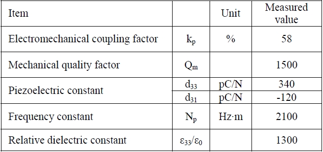
Dielectric and piezoelectric properties of piezoelectric ceramics.
2.2 Measurement of normal force dependence
The relationship between the normal force and maximum torque is expressed by the formula:

This equation is associated with the radius of the stator and the coefficient of friction between the rotor and stator. This torque relationship implies that the direction of the normal force is directly linked to the torque of the ultrasonic motor [9].
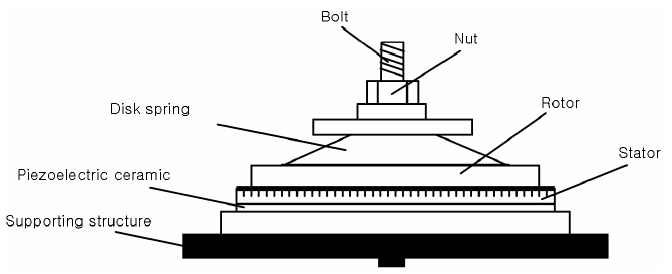
Figure 1 shows a jig for measuring the resonance characteristics of an ultrasonic motor. We detached the practical ultrasonic motor’s housing, exposed the stator and rotor and regulated the normal force by using a bolt and nut.
From initial measurements of the spring coefficient of the disk spring installed in the ultrasonic motor, the normal force was estimated to be about 90 N/mm. The measurement range of the normal force value was from 0 N to 225 N. The rotary power of the ultrasonic motor disappeared when the normal force exceeded 225 N. We measured the resonance frequency, anti-resonance frequency, impedance and phase of the motor by using a frequency response analyzer (FRA 5087, NF Corporation). In the case of a commercial motor with similar dimensions to our prototype, the normal force had a range of 150 ~ 180 N.
2.3 Measurement of input voltage dependence
In an ideal ultrasonic motor, the maximum torque and the no-load speed are determined by numerical formulas related to the voltage, current and the force factor [9]. In essence, the maximum torque increases in proportion to the input voltage until attaining a threshold value determined by the
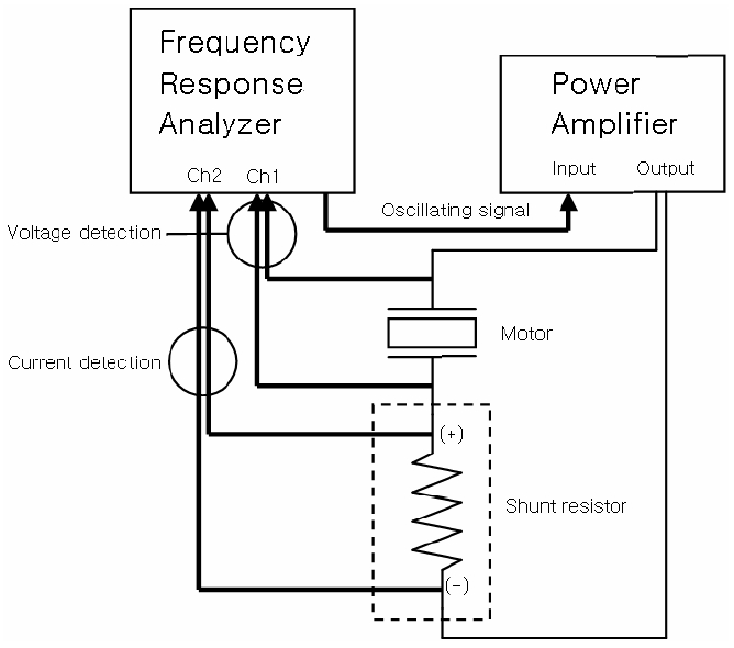
friction coefficient and the static normal force. Therefore, to increase the input voltage becomes expedient for torque augmentation, but the mechanical degradation of piezoelectric ceramics then happens more rapidly, curtailing the life span of the motor. The system for measuring the resonance characteristic as a function of input voltage is as shown in Fig. 2. The output of the internal oscillator in the frequency response analyzer is amplified by the power amplifier to drive the object being measured (ultrasonic motor) and the shunt resistor. The voltage at the motor to be measured is an input to Ch1 and the current flowing in the motor to be measured is converted into voltage by the shunt resistor and is an input to Ch2. By setting the analysis mode of the frequency response analyzer to Ch1/Ch2, the impedance of the motor is measured. By measuring the impedance while sweeping the frequency of the internal oscillator, we obtain the frequency-impedance characteristics. We measured the resonance characteristics of an ultrasonic motor for an input voltage in the range 1 to 70 Vrms.
2.4 Measurement of normal force and input voltage dependence
Piezoelectric ceramics, used in the common ultrasonic motor, vibrate under the condition that hundreds of voltage signals and large amounts of pressure are applied simultaneously. Therefore, investigation of the characteristics of piezoelectric ceramics in these conditions has a considerable significance. The torque, obtained by multiplying the voltage and normal force of a motor, can be improved [5]. However, if the magnitudes of the voltage and normal force increase over limiting values, the performance of the motor deteriorates.
2.5 Electromechanical coupling coefficient
The coefficient of electromechanical coupling represents the mechanical energy accumulated in a ceramic or crystal and it is related to the total electrical input voltage. This
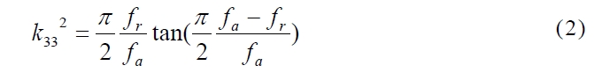
coefficient k can be calculated for each individual vibration mode of resonant and anti- resonant frequencies. In order to analyze the variation tendency of the longitudinal coupling factor k33 due to changes of the input voltage and normal force, a measurement method calculated indirectly by means of the resonance method of the IRE standards is used. In accordance with the IRE standards, the value of k33 can be calculated from the following formula using the resonance method [3]. Then k33 is determined from the resonance frequency and anti-resonance frequencies.
3. EXPERIMENTAL RESULTS AND DISCUSSION
3.1 Normal force measurement results
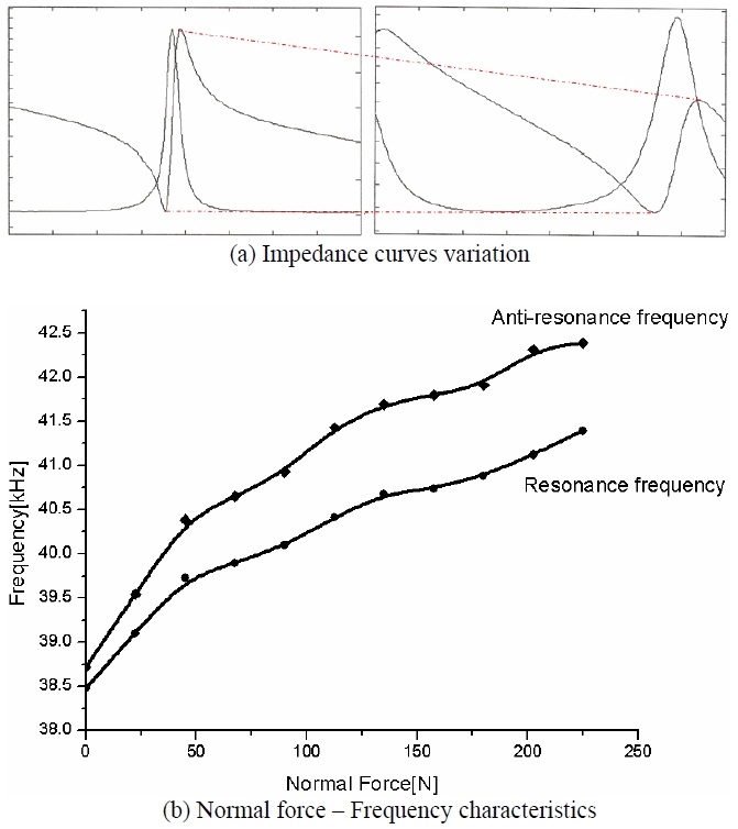
Figure 3 shows the normal force dependence of the resonance characteristics of an ultrasonic motor. Figure 3(a) shows the shape of the impedance curves when the normal forces are 0 N and 225 N respectively. When the normal force exists, the range of impedance change between the resonance and anti-resonance points decreased and the difference between the points (Δf = fa - fr) was increased. The magnitude of the input voltage applied to the piezoelectric ceramic was 1 Vrms in this experiment. Figure 3(b) is a graph that expresses the change of frequency as a function of the normal force. The resonance frequency difference measured between maximum force and zero force was about 3 kHz. The anti-resonance frequency was 5 kHz.
3.2 Effect of input voltage measurement results
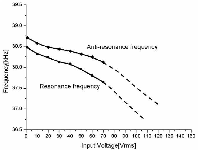
The variation of the resonance and anti-resonance frequencies for the domain of input voltage is shown in Fig. 4. With increasing input voltage, the frequencies diminished and Δf became larger. However, contrary to the behavior of the normal force, the range of the impedance change between the resonance and anti-resonance points was regular and independent of the input voltage. In this experiment, input voltages ranging from 1 to 70 Vrms were applied to the prototype motor. Over this range, the separation of the points decreased with decreasing input voltage. Near the actual driving voltage (120 Vrms), the gap between the resonance frequency and anti-resonance frequency became larger than that in the lower voltage range. Hence, the frequencies at 120 Vrms became 1.5 ~ 2 kHz lower than that measured values at an input voltage of under 1 Vrms. We say that the increase in vibration displacement due to the increment of applied voltage causes a shorter vibration cycle and it finally reduces the resonance frequency.
3.3 Normal force and input voltage measurement results
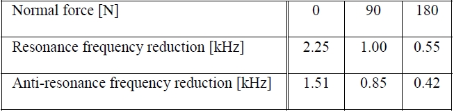
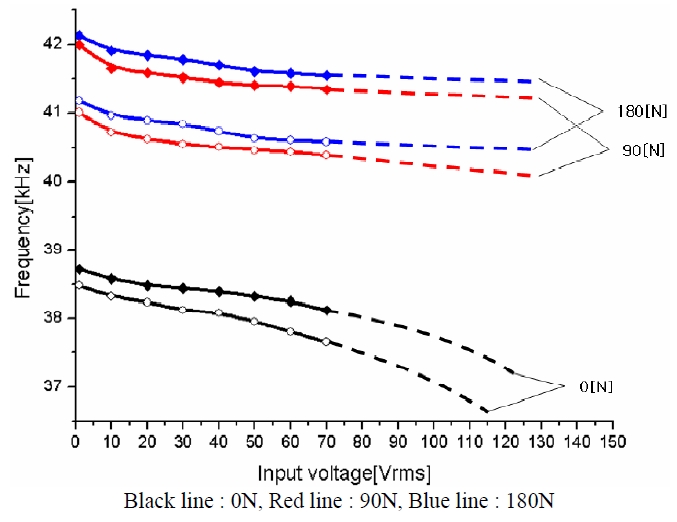
Figure 5 shows the change of frequencies when the normal force and input voltage are applied simultaneously. The resonance characteristics are regular in comparison with the behavior found in prior experiments. We tabulate the frequency reduction between the frequency measured at 1 Vrms and the frequency estimated at 120 Vrms in Table 2. As the normal force increases, the frequency variation of the resonance and anti- resonance frequencies with input voltage decreases as shown in Fig. 5. This shows that the resonance characteristics of the ultrasonic motor are affected by both the input voltage and normal force. On the other hand, remarkably, Δf is not influenced by the change of input voltage with a normal force exists.
3.4 Electromechanical coefficient calculation result
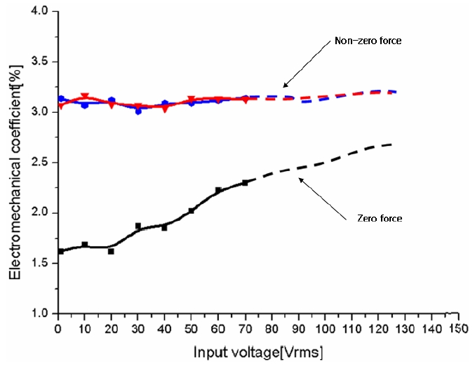
Figure 6 shows the normal force and input voltage dependence of the electromechanical coefficient k33. From the frequencies that we measured in prior experiments, we
[Table 2.] Frequency reduction depending on normal force and input voltage.

Frequency reduction depending on normal force and input voltage.
calculated k33 as a function of the input voltage and normal force. In the case of zero force, the values of the coefficient show an increasing tendency as the voltage increases. In contrast, with a non-zero force, the coefficient maintains an almost constant value. For example for normal forces of 90 N and 180 N, k33 is almost same.
In this paper, we have analyzed the variations in resonance characteristics of a travelling wave rotary type ultrasonic motor with normal force and input voltage. The ultrasonic motor is operated using the vibration of piezoelectric ceramics when an alternating voltage is applied and the friction force between the stator and rotor are as shown in Fig. 1. Therefore, we can determine that the magnitude of the input voltage and normal force that create the frictional force has a serious effect on the performance of the ultrasonic motor. The analysis of the resonance behavior of the ultrasonic motor as a function accordance of the above stated electrical conditions (input voltage, resonance frequency) and mechanical conditions (normal force) has turned out to be useful research. As the normal force increased, the resonance and anti-resonance frequencies were increased, but the input voltage increased, those frequencies were decreased. Therefore, when the two conditions were applied simultaneously, the resonance characteristics were affected in a complex way. Generally, the characteristics of piezoelectric ceramics are measured under a low voltage and zero- normal force condition.
However the electrical and mechanical conditions to which the piezoelectric element is exposed are quite different from the conditions determined by IRE standards as applied to ultrasonic motors. We confirmed in this research that the resonance characteristics showed a noticeable change. As the parameters for the performance evaluation of ultrasonic motors are based on the static characteristics of component material, these parameters show variations under the operation conditions of ultrasonic motors. These facts have been proved experimentally in this research. Therefore, the qualitative and quantitative data obtained about the dynamical properties of piezoelectric ceramics can be utilized for the assessment of the attainable performance of ultrasonic motors under normal operating conditions. This will help to achieve uniformity and reliability of the performance of ultrasonic motors in industrial mass production.