There have been many studies of and much development of panoramic imaging systems not only in the traditional areas such as photographing buildings, nature scenes, and heavenly bodies, but also in security/surveillance systems using CCD (charge-coupled device) or CMOS (complementary metal-oxide-semiconductor) cameras, in virtual touring of real estate, hotels and tourist resorts, and in navigational aids for mobile robots and unmanned aerial vehicles (UAV) [1-22].
Reference 19 provides examples of stereo panoramic images produced by Professor Paul Bourke. Each of the panoramic images follows a cylindrical projection scheme, and a panoramic image of an imaginary scene produced by a computer as well as a panoramic image produced by a rotating slit camera are presented. For panoramic images produced by a computer or produced by a traditional method of rotating slit camera, the lens distortion is not an important issue. Provided the lens mounted on the rotating head panoramic camera is a distortion-free rectilinear wideangle lens, the panoramic image produced by the rotating head panoramic camera is an ideal panoramic image having a cylindrical projection scheme. However, a rotating slit camera cannot be used to take a real-time panoramic movie of a real world. Furthermore, the horizontal field of view of a commercial rotating head panoramic camera is limited to around 140°.
A cheaper alternative to the panoramic image acquisition method by the previously described camera with a horizontally- rotating lens, consists of taking an image with an ordinary camera with the optical axis horizontally aligned, and repeating to take pictures after horizontally rotating the optical axis by a certain amount. Four to eight pictures are taken in this way, and a panoramic image with a cylindrical projection scheme can be obtained by seamlessly joining the pictures consecutively. Such a technique is called stitching. QuickTime VR from Apple computer inc. is commercial software supporting this stitching technology[9-10]. This method requires a complex, time-consuming, and elaborate operation of precisely joining several pictures and correcting the lens distortion.
As another viable method of obtaining panoramic images, people are actively researching catadioptric panoramic imaging systems, which are imaging systems employing both mirrors and refractive lenses[4, 6, 11, 13-15, 18, 20-22]. Catadioptric panoramic lenses take panoramic images in one shot with the optical axes of the panoramic lenses aligned vertical to the ground plane. By properly designing the mirror profile, the necessary image processing load can be kept at a minimum[20-22]. Nevertheless, catadioptric panoramic lenses tend to be rather bulky and costly.
Another method of obtaining a panoramic image is to employ a fisheye lens with a wide field of view (FOV). For example, the entire sky and the horizon can be captured in a single image by pointing a camera equipped with a fisheye lens with 180° FOV toward the zenith[1]. For this reason, fisheye lenses have often been referred to as "all-sky lenses". In particular, a high-end fisheye lens by Nikon, namely, 6mm f/5.6 Fisheye-Nikkor, has a FOV of 220°. Therefore, a camera equipped with this lens can capture a portion of the view behind the camera as well as in front of the camera. Then, after proper image processing, a panoramic image can be obtained from the fisheye image. Image processing on fisheye image has been an active investigation area for the past several decades[2-3, 23-26].
From another point of view, all animals and plants including humans are bound on the surface of the earth due to the gravitational pull, and most of the events which need attention or cautionary measures, take place near the horizon. Therefore, even though it is necessary to monitor every 360° direction on the horizon, it is not as important to monitor high along the vertical direction, for example, as high as to the zenith or deep down to the nadir. Distortion is unavoidable if we want to describe the scene of every 360° direction on a two-dimensional plane. Similar difficulty exists in the cartography where geography on earth, which is a structure on the surface of a sphere, needs to be mapped on a planar two-dimensional atlas.
Described in reference 27 are the well-known map projection schemes among the diverse map projection schemes such as equi-rectangular projection, Mercator projection and cylindrical projection schemes, and reference 28 provides a brief history of diverse map projection schemes. Among these, the equi-rectangular projection scheme is the projection scheme most familiar to us when we describe the geography on the earth, or when we draw the celestial sphere in order to make a map of the constellations.
Among all the distortions, the distortion that appears most unnatural to people is the distortion where vertical lines appear as curved lines. For example, people expect a person in a panoramic image to be standing in an upright position. Otherwise, the person may appear as having been maimed or as falling down, neither of which is a pleasant sight. Therefore, even if other kinds of distortions are present, it is important to make sure that this kind of distortion is absent. The goal of this investigation is to provide methods of extracting mathematically precise panoramic images and to build a panoramic camera providing such images.
II. PROJECTION SCHEMES OF FISHEYE LENS AND IDEAL PANORAMIC LENS
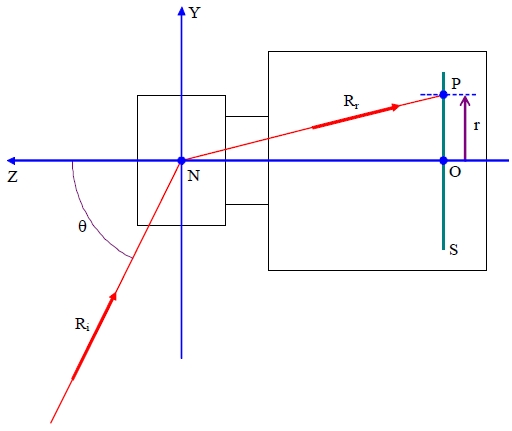
Figure 1 is a schematic diagram illustrating the projection scheme of a general wide-angle lens such as a fisheye lens[26]. The optical axis coincides with the Z-axis of the coordinate system, and the incidence angle θ of an incident ray Ri is measured as a zenith angle. All the rays forming image points on the image sensor plane S are considered to pass through the nodal point N of the lens. The intersection between the optical axis and the image sensor plane S is designated as origin O in Fig. 1. The refracted ray Rr corresponds to the incident ray Ri, and forms an image point P on the image sensor plane S. The radial distance from the origin O to the image point P is the image height
The general projection scheme of a lens can be defined as
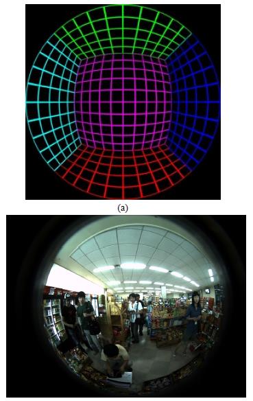
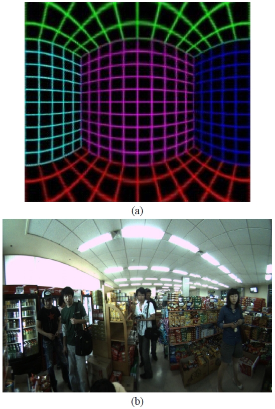
Figure 2(a) is an imaginary interior scene produced by Professor Paul Bourke by using a computer, and it has been assumed that the imaginary lens used to capture the scene is a fisheye lens with 180° FOV having an ideal equidistance projection scheme. This image is a square image, of which both the lateral and the longitudinal dimensions are 250 pixels. Therefore, the coordinate of the optical axis is (125.5, 125.5), and the image height for an incident ray with a zenith angle of 90° is given as r'(π/2) = 250 - 125.5 = 124.5. Here, r' is not a physical distance, but an image height measured in pixel distance. On the other hand, Fig. 2(b) is a fisheye image of an interior scene having 190° FOV. The real projection scheme of the fisheye lens used to capture this image is described in detail in reference 29.
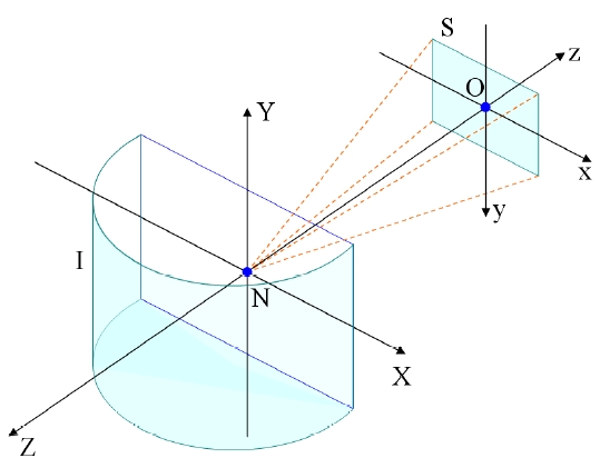
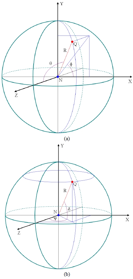
The projection scheme of a fisheye lens is different from the ideal projection scheme of a panoramic lens. Figure 3(a) shows the world coordinate system describing the object points in the outside world in the spherical polar coordinate system and Fig. 3(b) describe the same in the longitude-latitude system. The nodal point of the lens is taken as the origin of the world coordinate system, the vertical axis is taken as the Y-axis, and the optical axis is taken as the Z-axis. As has been illustrated in the figure, an object point Q is shown at a distance R from the origin N. All the object points are assumed as lying on a spherical object surface with a radius R. An incident ray originating from this object point Q will have a zenith angle θ and an azimuth angle φ in the world coordinate system. Referring to Fig. 3(b), the same incident ray will have a horizontal incidence angle ψ and a vertical incidence angle δ. Since there is no possibility of confusion, we will also designate the object surface as a celestial sphere, the horizontal incidence angle ψ as a longitude and the vertical incidence angle δ as a latitude.
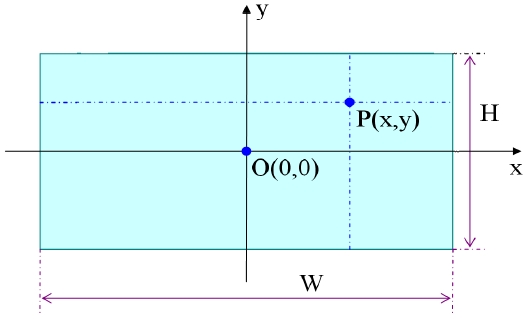
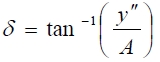
On the other hand, Fig. 4 is a schematic diagram of a planar map mapping the spherical surface on a two-dimension plane. A point Q on the object surface having a longitude ψ and a latitude δ has a corresponding point P on the planar map. The rectangular coordinate of this corresponding point is given as (x, y). Furthermore, the reference point on the equator having a longitude 0° and a latitude 0° has a corresponding point O on the planar map, and this corresponding point O is the origin of the rectangular coordinate system.
For the mapping to be a useful one, the lateral coordinate x must be a function only of the horizontal incidence angle(i.e., x = x(ψ)) and the longitudinal coordinate y must be a function only of the vertical incidence angle(i.e., y = y(δ)). Furthermore, for the mapping in Fig. 4 to be panoramic, the same interval in the longitude (i.e., the same angular distance along the equator) must corresponds to the same lateral interval on the planar map. In other words, the lateral coordinate x on the planar map is proportional to the longitude.

Here, c is a proportionality constant.
The exact functional dependence of the longitudinal coordinate y on the latitude δ depends on the particular projection scheme. If the planar map follows an equi-rectangular projection scheme, then the longitudinal coordinate y is also proportional to the latitude, and has the same proportionality constant as the lateral coordinate.
The span of the longitude is 360° ranging from -180° to +180°, and the span of the latitude is 180° ranging from -90° to +90°. Therefore, a map drawn according to the equi-rectangular projection scheme must have a width W: height H ratio of 360:180 = 2:1. Such an equi-rectangular projection scheme appears as a natural projection scheme for mapping the Earth's surface considering the fact that the Earth's surface is close to a spherical surface. Nevertheless, it is disadvantageous in that the size of a geographical area is greatly distorted. For example, two very close points near the North Pole can appear as if they are on the opposite sides of the Earth in a map drawn according to the equi-rectangular projection scheme.
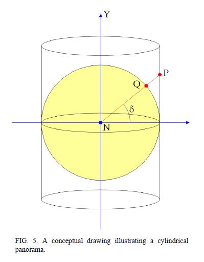
Fig. 5 is a conceptual drawing of a cylindrical projection scheme or a panoramic perspective. In a cylindrical projection
scheme, an imaginary observer is located at the center N of a celestial sphere with a radius R, and it is desired to make a map of the celestial sphere centered on the observer, the map covering most of the region excluding the zenith and the nadir. In other words, the span of the longitude can be as large as 360° ranging from -180° to +180°, but the span of the latitude is narrow ranging from -δ to +δ, where δ must be smaller than 90°.
In this projection scheme, a hypothetical cylindrical plane is assumed which contacts the celestial sphere at the equator. Then, for a point Q(ψ, δ) on the celestial sphere having a given longitude ψ and a latitude δ, a line segment connecting the center N of the celestial sphere and the object point Q is extended until it meets the cylindrical plane. This intersection point is designated as P(ψ, δ). In this manner, the corresponding point P on the cylindrical plane can be obtained for every object point Q on the celestial sphere within the given latitude range. Then, a map having a cylindrical projection scheme is obtained by cutting the cylindrical plane and laying flat on a planar surface. Therefore, the lateral coordinate of the point P on the flattened-out cylindrical plane is given by Eq. 1, and the longitudinal coordinate y is given by Eq. 3.
Such a cylindrical projection scheme is the natural projection scheme for a panoramic camera that produces a panoramic image by rotating in the horizontal plane. Especially, if the lens mounted on the rotating panoramic camera is a distortion-free rectilinear lens, then the resulting panoramic image exactly follows a cylindrical projection scheme. In principle, such a cylindrical projection scheme is the most accurate panoramic projection scheme. However, the panoramic image appears unnatural when the latitudinal range is large, and thus it is not widely used in practice.
Another widely used projection scheme is the Mercator projection scheme. In a map drawn according to the Mercator projection scheme, the longitudinal coordinate is given as a complex function given in Eq. 4.
The Mercator projection scheme does not have any obvious geometrical meaning. The Mercator projection scheme is related to sinh function while the cylindrical projection scheme is related to tan function.
III. CHARACTERISTICS OF CYLINDRICAL PANORAMIC IMAGE
The projection scheme of a fisheye lens is different from the ideal projection scheme of a panoramic lens. Figure 6 illustrates the projection scheme of a hypothetical panoramic lens providing a cylindrical panorama. The panoramic lens is assumed as attached on a vertical wall. The wall coincides with the X-Y plane of the world coordinate system, and the Y-axis runs from the ground plane(i.e., X-Z plane) to the zenith. The origin of the coordinate is located at the nodal point N of the lens, and the optical axis of the lens coincides with the Z-axis. The world coordinate system is a coordinate system for describing the environment that is captured by the lens.
In a rigorous sense, the direction of the optical axis is the direction of the negative Z-axis of the world coordinate system. This is because, by the notational convention of imaging optics, the direction from the object(or, an object point) to the image plane(or, an image point) is the positive direction. Despite this fact, we will describe the optical axis as coinciding with the Z-axis of the world coordinate system for the sake of simplicity in argument.
The image sensor plane S is a plane having a rectangular shape and perpendicular to the optical axis, whereof the lateral dimension is B, and the longitudinal dimension is V. Here, we assume a first rectangular coordinate system, wherein the nodal point N of the lens is taken as the origin, and the optical axis is taken as the negative z-axis. In other words, the direction of the z-axis is the exact opposite direction of the Z-axis. The intersection point between the z-axis and the image sensor plane S is O. The x-axis of the first rectangular coordinate system passes through the intersection point O and is parallel to the lateral side of the image sensor plane, and the y-axis passes through the intersection point O and is parallel to the longitudinal side of the image sensor plane.
The X-axis of the world coordinate system is parallel to the x-axis of the first rectangular coordinate system, and points in the same direction. On the other hand, the Y-axis of the world coordinate system is parallel to the y-axis of the first rectangular coordinate system, but the direction of the Y-axis is the exact opposite of the direction of the y-axis. Therefore, in Fig. 6, the positive direction of the x-axis of the first rectangular coordinate system runs from the left to the right, and the positive direction of the y-axis runs from the top to the bottom. This complies with the convention in digital image processing.
The intersection point O between the z-axis of the first rectangular coordinate system and the sensor plane S will be referred to as the first intersection point. The first intersection point is not generally located at the center of the sensor plane, and it can even be located outside the sensor plane. Such a case can happen when the center of the image sensor is moved away from the center position of the lens - i.e., the optical axis - on purpose in order to obtain an asymmetric vertical or horizontal field of view.
The lateral coordinate x of an arbitrary point P - hereinafte
Schematically shown in Fig. 6, a hypothetical panoramic lens providing a cylindrical panoramic image assumes a hemi-cylindrical object plane I with a radius γ and having the Y-axis as the rotational symmetry axis, and the image of an arbitrary object point Q on the object plane appears as an image point P on the sensor plane S. The image of an object on the hemi-cylindrical object plane I is captured on the sensor plane with its vertical proportions preserved, and the lateral coordinate x of the image point is proportional to the horizontal arc length of the corresponding object point on the object plane, and the image points on the image sensor plane by all the object points on the object plane collectively form a real image. When such a condition is satisfied, the obtained image follows a rectilinear projection scheme in the vertical direction, and follows an equidistance projection scheme in the horizontal direction.
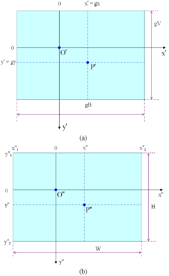
An arbitrary rotationally symmetric lens including a fisheye lens, however, does not follow such a projection scheme. Therefore, to realize such a projection scheme, an image processing stage is inevitable. Fig. 7(a) is a conceptual drawing of an uncorrected image plane prior to the image processing stage, which corresponds to the image sensor plane S. If the lateral dimension of the image sensor plane S is B and the longitudinal dimension is V, then the lateral dimension of the uncorrected image plane is gB and the longitudinal dimension is gV, where g is a proportionality constant [26].
The first intersection point O is the intersection point between the optical axis and the image sensor plane S. Therefore, a ray entered along the optical axis forms an image point on the first intersection point O. By definition, the horizontal incidence angle ψ and the vertical incidence angle δ of a ray entered along the optical axis are both zero. Therefore, the point O' on the uncorrected image plane corresponding to the first intersection point O in the image sensor plane - hereinafte
A second rectangular coordinate systems is assumed wherein x'-axis is taken as the axis that passes through the second intersection point O' and is parallel to the lateral side of the uncorrected image plane, and y'-axis is taken as the axis that passes through the second intersection point and is parallel to the longitudinal side of the uncorrected image plane. In Fig. 7(a), the positive direction of the x'-axis runs from the left to the right, and the positive direction of the y'-axis runs from the top to the bottom. Then, the lateral coordinate x' of an arbitrary image point P' on the uncorrected image plane has a minimum value x'1 = gx1 and a maximum value x'2 = gx2(i.e., gx1 ≤ x' ≤ gx2). In the same manner, the longitudinal coordinate y' of the image point has a minimum value y'1 = gy1 and a maximum value y'2=gy2(i.e., gy1 ≤ y' ≤ gy2).
Figure 7(b) is a conceptual drawing of a processed image plane showing ideal panoramic images. The processed image plane has a rectangular shape, whereof the lateral side measures as W and the longitudinal side measures as H. Furthermore, a third rectangular coordinate system is assumed wherein x''-axis is parallel to the lateral side of the processed image plane, and y''-axis is parallel to the longitudinal side of the processed image plane. The z''-axis of the third rectangular coordinate system is parallel to the z-axis of the first rectangular coordinate system and the z'-axis of the second rectangular coordinate system. The intersection point O'' between the z''-axis and the processed image plane can take an arbitrary position, and it can even be located outside the processed image plane. In Fig. 7(b), the positive direction of the x''-axis runs from the left to the right, and the positive direction of the y''-axis runs from the top to the bottom. Table 1 summarizes the various coordinate systems defined in this section.
[TABLE 1.] Correspondences between different planes defined in this article
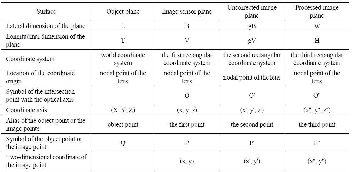
Correspondences between different planes defined in this article
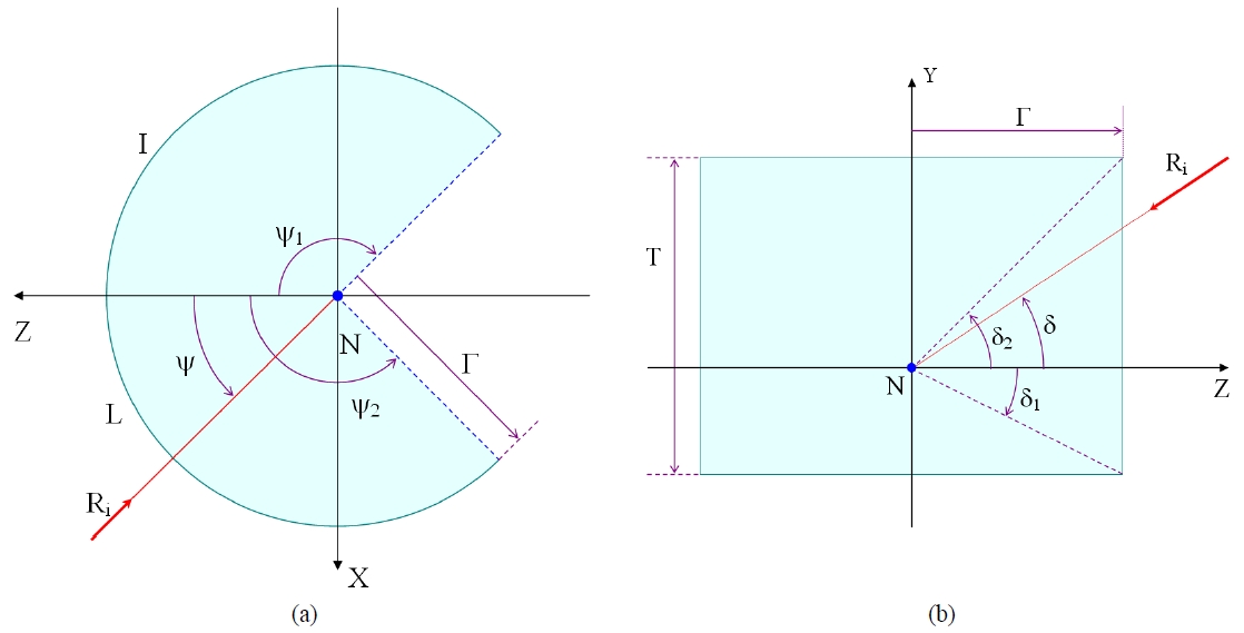
Conceptual drawing of (a) a horizontal cross-section of the object plane (b) a vertical cross-section of the object plane.
The minimum value of the horizontal incidence angle is ψ1, the maximum incidence angle is ψ2(i.e., ψ1 ≤ ψ ≤ ψ2), and the horizontal FOV is δψ = ψ2 - ψ1. In general, if the horizontal FOV is 180°, then a desirable range of the horizontal incidence angle will be given by ψ2 = -ψ1 = 90°. Since the radius of the object plane is γ, the arc length of the object plane is given by Eq. 5.
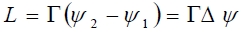
Here, it has been assumed that the unit of the field of view δψ is radians. This arc length L must be proportional to the lateral dimension W of the processed image plane. Therefore, if this proportionality constant is c, then the following Eq. 6 is satisfied.

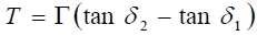
On the other hand, Fig. 8(b) shows the cross-section of the object plane I in Fig. 6 in the Y-Z plane. The radius of the object plane I is γ, and the height of the object plane is T. The vertical incidence angle of a ray entering into the lens, which is the angle with respect to the Z-axis(i.e., the optical axis) in the Y-Z plane(i.e., a plane containing a vertical line), is δ. In other words, the vertical incidence angle the incident ray makes with the X-Z plane is δ. The minimum value of this vertical incidence angle is δ1, and the maximum value is δ2 (i.e., δ1 ≤ δ ≤ δ2). When the vertical FOV is δδ = δ2 - δ1, it is simpler if the range of the vertical incidence angle is given as δ2 = - δ1 = δδ/2, but according to the needs, it may be desirable if the two values are different. For example, if it is installed on the roof of a vehicle, then it is desirable to mainly monitor the area above the horizon, but if it is installed on an airplane, it is desirable to mainly monitor the area below the horizon. Here, the height T of the object plane seen from the origin N of the coordinate system is given by Eq. 7.
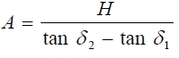
Furthermore, the height T of the object plane must satisfy the same proportionality relation with the height H of the processed image plane.

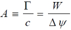
Equation 9 can be obtained from Eqs. 5 and 6, wherein A is a constant.
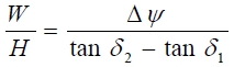
On the other hand, Eq. 10 can be obtained from Eqs. 7 and 8.
Therefore, from Eqs. 9 and 10, it can be seen that the following equation must be satisfied.
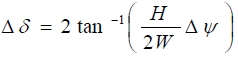
In most of the cases, it will be desirable if the range of the horizontal incidence angle and the range of the vertical incidence angle are symmetrical. When designing a lens or evaluating the characteristics of a lens, the horizontal FOV δψ and the vertical FOV δδ are important parameters. From Eq. 11, it can be seen that the symmetrical vertical FOV must be given as in Eq. 12 as a function of the symmetrical horizontal FOV.
More generally, when the procedure from Eq. 5 through Eq. 10 is repeated on an interval containing the third intersection point O'', then Eq. 13 can be obtained.

Therefore, when setting-up the desirable size of the processed image plane and the FOV, it must be ensured that Eq. 13 is satisfied.
IV. IMAGE-PROCESSING ALGORITHM FOR OBTAINING PANORAMIC IMAGES FROM FISHEYE IMAGES
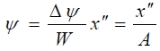
If the processed image plane in Fig. 7(b) satisfies the cylindrical panoramic projection scheme, then the horizontal incidence angle of an incident ray corresponding to the lateral coordinate x'' of a third point P'' on the processed image plane is given by Eq. 14.
Likewise, the vertical incidence angle of an incident ray corresponding to the third point having a longitudinal coordinate y'' is given as Eq. 15.
Therefore, the signal value of a third point on the processed image plane having an ideal cylindrical panoramic projection scheme must be given as the signal value of an image point on the image sensor plane formed by an incident ray originating from an object point on the object plane having a horizontal incidence angle(i.e., the longitude) given by Eq. 14 and a vertical incidence angle(i.e., the latitude) given by Eq. 15.
The location of the object point Q on the object plane having given horizontal and vertical incidence angles can be obtained by the following method. Referring to Fig. 3(b), a vector from the origin N of the world coordinate system to an object point Q on the object plane having given horizontal and vertical incidence angles can be written as
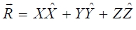
In Eq. 16, (X)= (1,0,0) is the unit vector along the X-axis, and likewise, (?)= (0,1,0) and (?)= (0,0,1) are the unit vectors along the Y-axis and the Z-axis, respectively. On the other hand, the vector

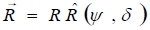
can be given in the spherical polar coordinate system as a function of the zenith angle θ and the azimuth angle φ as given in Eq. 17.
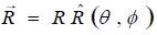
Here, R is the magnitude of the vector
and

is the direction vector. Then, the following relation holds between the rectangular coordinate and the spherical polar coordinate.
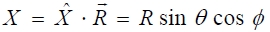
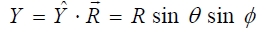
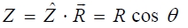
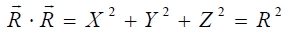
In Eqs. 18 through 21, dot(?) represents a scalar product.
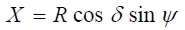
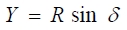
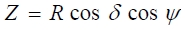
On the other hand, the direction vector can be given by Eq. 22 as a function of two incidence angles describing the projection scheme, namely the horizontal incidence angle ψ and the vertical incidence angle δ. Hereinafter, this coordinate system will be referred to as a cylindrical polar coordinate system.
Using these two incidence angles, the rectangular coordinate can be given as follows.
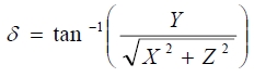
Using Eqs. 23 through 25, the horizontal and the vertical incidence angles can be obtained from the rectangular coordinate (X, Y, Z) of the object point as in Eqs. 26 and 27.
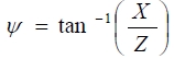
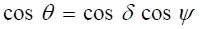
Since the coordinates given in the spherical polar coordinate system and in the cylindrical polar coordinate system must agree, the following relations given in Eqs. 28 through 30 must hold.
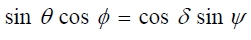

Eq. 31 can be obtained by dividing Eq. 29 by Eq. 28.
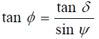
Therefore, the azimuth angle φ is given by Eq. 32.

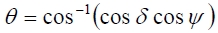
From Eq. 30, the zenith angle θ is given by Eq. 33.
Therefore, an incident ray having a horizontal incidence angle ψ and a vertical incidence angle δ is an incident ray in the spherical polar coordinate system having a zenith angle θ given by Eq. 33 and an azimuth angle φ given by Eq. 32. In order to process an image, the position on the image sensor plane corresponding to an incident ray having such a zenith angle θ and an azimuth angle φ must be determined.
It has been assumed that the projection scheme of a lens is given as a general function of the zenith angle θ of the incident ray as given in Eq. 34.

This function is a monotonically increasing function of the zenith angle θ of the incident ray.
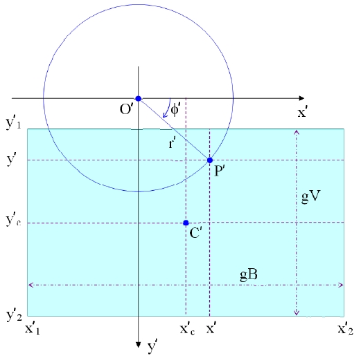
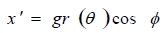
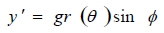
Figure 9 is a conceptual drawing illustrating the conversion relation between the rectangular coordinate and the polar coordinate of the second point P' on the uncorrected image plane corresponding to the first point on the sensor plane. Referring to Fig. 9, the two-dimensional rectangular coordinate (x', y') of the second point on the uncorrected image plane can be obtained from the two-dimensional polar coordinate (r', φ' ≡ φ) as in Eqs. 35 and 36.
Using Eqs. 14 through 36, a panoramic image having an ideal projection scheme can be extracted from an image acquired using a fisheye lens exhibiting a distortion aberration. First, depending on the user's need, a desirable size (W, H) of the panoramic image and the location of the third intersection point O" are determined. The third intersection point can be located even outside the processed image plane. In other words, the range of the lateral coordinate (x''1 ≤ x'' ≤ x''2) on the processed image plane as well as the range of the longitudinal coordinate (y''1 ≤ y'' ≤ y''2) can take arbitrary real numbers. Also, the horizontal FOV δ ψ of this panoramic image(i.e., the processed image plane) is determined. Then, the horizontal incidence angle ψ and the vertical incidence angle δ of an incident ray corresponding to the third point in the panoramic image having a rectangular coordinate (x'', y'') can be obtained using Eqs. 14 and 15. Then, the zenith angle θ and the azimuth angle φ of an incident ray having given horizontal and the vertical incidence angles are calculated using Eqs. 32 and 33. Next, the real image height r corresponding to the zenith angle θ of the incident ray is obtained using Eq. 34. Utilizing the real image height r, the magnification ratio g, and the azimuth angle φ of the incident ray, the rectangular coordinate (x', y') of the image point on the uncorrected image plane is obtained using Eqs. 35 and 36.
In this procedure, the coordinate of the second intersection point on the uncorrected image plane, or equivalently the location of the first intersection point on the sensor plane has to be accurately determined. Such a location of the intersection point can be easily found using various methods including image processing method. Since such technique is well known to the people in this field, it will not be described in this document. Finally, the video signal (i.e., RGB signal) from the image point by the fisheye lens having this rectangular coordinate is given as the video signal for the image point on the panoramic image having the rectangular coordinate (x'', y''). A panoramic image having an ideal projection scheme can be obtained by image processing for all the image points on the processed image plane by the above-described method.
A complication arises due to the fact that all the image sensors and display devices are digitized devices. Processed image plane has pixels in the form of a two-dimensional array having Jmax columns in the lateral direction and I''max rows in the longitudinal direction. Although, in general, each pixel has a square shape with both the lateral dimension and the longitudinal dimension measuring as p, the lateral and the longitudinal dimensions of a pixel are considered as 1 in the image processing field. To designate a particular pixel P'', the row number I and the column number J are used. Therefore, the signal stored on this pixel can be designated as S(I, J). A pixel has a finite area. To correct the distortion of a digitized image, the physical coordinate of an arbitrary pixel P'' is taken as the center position of the pixel.
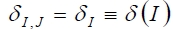
There is an image point - i.e., the first point - on the image sensor plane corresponding to a pixel P'' on the processed image plane. The horizontal incidence angle of an incident ray in the world coordinate system forming an image at this first point can be written as ψI,J ≡ ψ(I, J). Also, the vertical incidence angle can be written as δI,J ≡ δ(I, J). Incidentally, the location of this first point does not generally coincide with the exact location of any one pixel.
Here, if the processed image plane corresponds to a panoramic image, then as given by Eq. 37, the horizontal incidence angle must be a sole function of the lateral pixel coordinate J.

Likewise, the vertical incidence angle must be a sole function of the longitudinal pixel coordinate I.
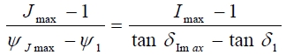
Furthermore, if an equidistance projection scheme is satisfied in the lateral direction, and a rectilinear projection scheme is satisfied in the longitudinal direction, then the range of the horizontal incidence angle and the range of the vertical incidence angle must satisfy the relation given in Eq. 39.
Comparing with the image processing method described previously, the image processing method for a digitized image goes through the following procedure. First, the real projection scheme of the wide-angle lens that is meant to be used in the image processing is obtained either by experiment or based on the accurate lens prescription.

This function is a monotonically increasing function of the zenith angle θ. Next, the location of the optical axis on the uncorrected image plane, in other words, the location of the second intersection point O' corresponding to the first intersection point O on the image sensor plane is obtained. The pixel coordinate of this second intersection point is assumed as (Ko, Lo). In addition to this, the magnification ratio g of the pixel distance r' on the uncorrected image plane over the real image height r on the image sensor plane is obtained. This magnification ratio g is given by Eq. 41.

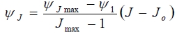
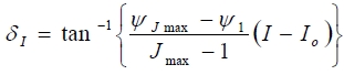
Once such a series of preparatory stages have been completed, then a camera mounted with a fisheye lens is installed with its optical axis aligned parallel to the ground plane, and a raw image(i.e., an uncorrected image plane) is acquired. Next, the desirable size of the processed image plane and the location (Io, Jo) of the third intersection point is determined, and then the horizontal incidence angle ψJ and the vertical incidence angle δI given by Eqs. 42 and 43 are computed for all the pixels (I, J) on the processed image plane.
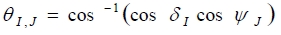
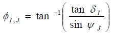
From these horizontal and vertical incidence angles, the zenith angle θI,J and the azimuth angle φI,J of the incident ray in the first rectangular coordinate system are obtained using Eqs. 44 and 45.
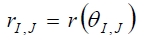
Next, the image height rI,J on the image sensor plane is obtained using Eqs. 40 and 44.
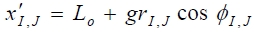
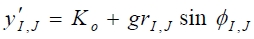
Next, using the location (Ko, Lo) of the second intersection point on the uncorrected image plane and the magnification ratio g, the location of the second point on the uncorrected image plane is obtained using Eqs. 47 and 48.
The location of the second point does not exactly coincide with the location of any one pixel. Therefore, (
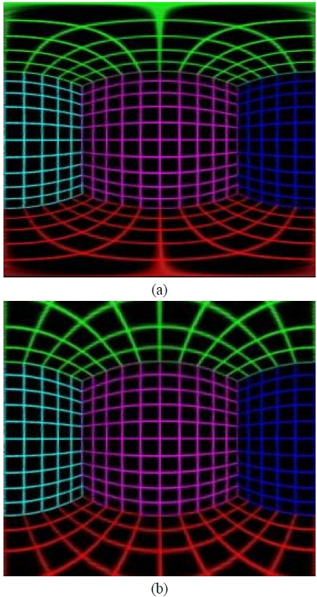
Figure 10(a) is a panoramic image following a cylindrical projection scheme that has been extracted from the image in Fig. 2(a), where the lateral and the longitudinal dimensions are all 250 pixels, and the third intersection point is located at the center of the processed image plane. Furthermore, the horizontal FOV of the processed image plane is 180°(i.e., π). As can be seen from Fig. 10(a), all the vertical lines in the three walls, namely the front, the left, and the right walls in Fig. 2(a) appear as straight lines in Fig. 10(a). The fact that all the vertical lines in the world coordinate system appear as straight lines in the processed image plane is the characteristic of a panoramic image. On the other hand, Fig. 10(b) is the panoramic image that has been extracted from the image in Fig. 2(b) by following a cylindrical projection scheme.
In a panoramic image following a cylindrical projection scheme, at least a portion on the top and the bottom region in an original fisheye image cannot appear in the panoramic image. This is due to the existence of the tangent function in the projection scheme in the vertical direction.
On the other hand, Fig. 11(a) is a panoramic image following an equi-rectangular projection scheme extracted from the fisheye image given in Fig. 2(a), and Fig. 11(b) is a panoramic image following a Mercator projection scheme. Especially in the panoramic image in Fig. 11(a) with an equi-rectangular projection scheme, the horizontal and the vertical FOVs are both 180°. Therefore, all the information that exists in the original image also exists in the panoramic image, but no more.
VI. PANORAMIC IMAGE PROCESSING MODULE
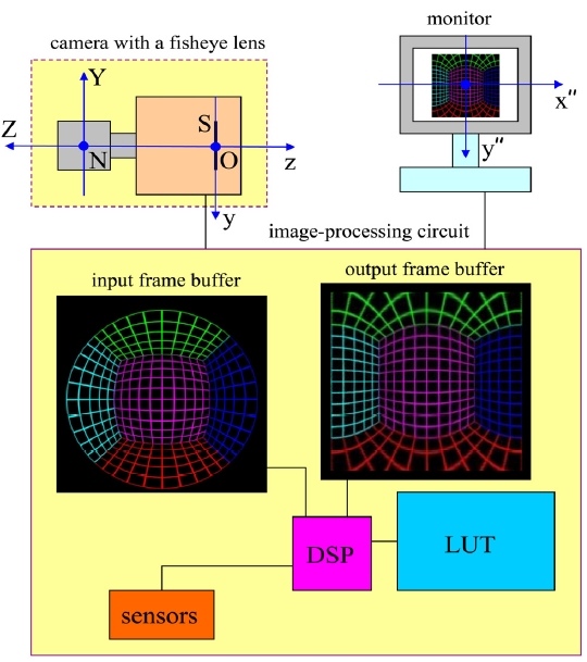
Figure 12 is a schematic diagram of a panoramic image processing module. The image processing module has an input frame buffer storing one frame of image acquired from the camera mounted with a fisheye lens. The input frame buffer stores a digital image acquired from the camera in the form of a two dimensional array. This digital image is the uncorrected image plane. The output frame buffer stores an output signal in the form of a two dimensional array, which corresponds to the processed image plane that can be displayed on a monitor. A central processing unit(CPU) generates a processed image plane from the uncorrected image plane existing in the input frame buffer and stores in the output frame buffer. The mapping relation between the output frame buffer and the input frame buffer is stored in a non-volatile memory such as a NOR Flash in the form of a lookup table(LUT). In other words, a long list of pixel addresses for the input frame buffer corresponding to particular pixels in the output frame buffer is generated and stored. Central processing unit refers to this list stored in the nonvolatile memory in order to process the image. If necessary, the operation of the image processing module can be made to react to input signals from various sensors.
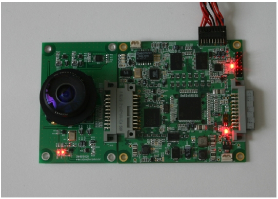
Figure 13 shows a developed panoramic image processing module. The fisheye lens described in reference 29 is used, and a progressive scan CMOS image sensor(model: MT9D131) from Micron is used as the image sensor. This sensor is a 1/3.2-inch sensor having 1600×1200 pixels. Since this is a SOC(System-on-a chip) sensor, camera head board is easily built. A DSP chip (model: TMS320DM6437) has been chosen as the CPU. The CMOS image sensor has been programmed to operate in preview mode, where the 2Mega pixels image has been binned to output 800×600 images. From this uncorrected image plane, processed image plane having 720×480 pixels(i.e., D1-grade) has been generated. Due to the size mismatch between the fisheye lens and the CMOS image sensor, the captured image has a horizontal FOV of 175°. The DSP chip has been verified to be able to process 30 frames/second for D1-grade panoramic images. However, the frame rate has been limited by the CMOS image sensor, which slows down unless the scene is brightly illuminated.
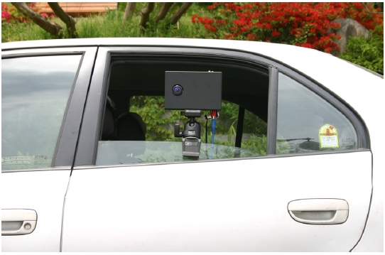
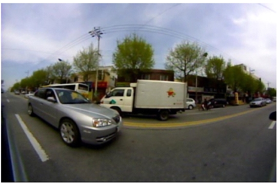
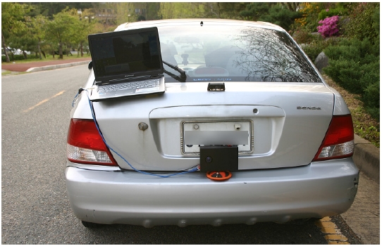
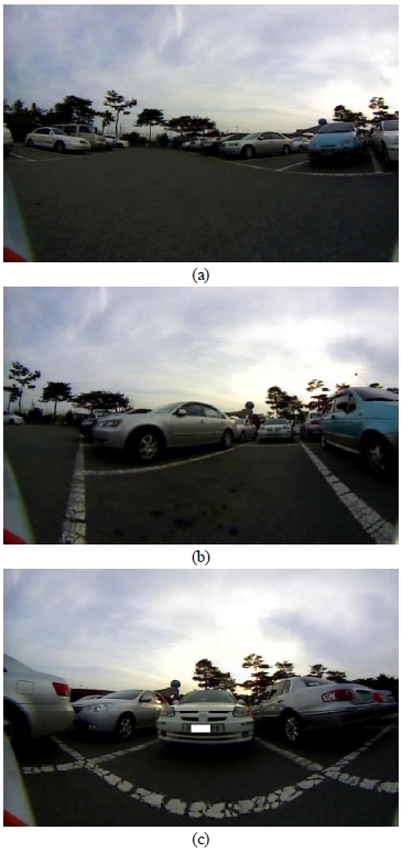
Figure 14 shows the developed panoramic camera mounted on a side-window of a passenger car, and Fig. 15 is a sample image captured while driving through a busy street. Fig. 16 shows the panoramic camera installed near the rear bumper of a passenger car. Fig. 17 shows a series of still images captured while parking the car.
In conclusion, we have developed mathematically precise image-processing algorithms for extracting panoramic images from fisheye images. Furthermore, we have successfully built a DSP-based panoramic camera employing a single fisheye lens. Imaging systems using this method can be used not only in security/surveillance applications for indoor and outdoor environments, but also in diverse areas such as video phones for apartment entrance doors, rear view cameras for vehicles, visual sensors for unmanned aerial vehicles and robots, and broadcasting cameras.