We report, for the first time to our knowledge, observation of polarization bistability from 1.55-㎛wavelength single-mode VCSELs of a conventional cylinder-shape under control of their driving current,and demonstration of all-optical flip-flop (AOFF) operations based on the bistability with optical set andreset pulse injection at a 50 MHz switching frequency. The injection pulse energy was less than 14 fJ.The average on-off contrast ratio of the flip-flopped signals was about 7 dB. These properties of theVCSELs will be potentially useful for future high-speed all-optical signal processing applications.
All-optical flip-flop (AOFF) devices are known to be very important for high-speed optical switches, optical logic gates, optical routers, signal regeneration devices and optical memories for future high-speed optical networks. Significant research has been done for AOFF operation based on various semiconductor optical devices such as Fabry-Perot Laser diodes (FP LDs), distributed feedback (DFB) LDs, semiconductor optical amplifier (SOA) and microdisk lasers [1-11]. An ultimate goal of such devices is demonstration of low power consumption, high-speed operation, and high-density integration for practical system applications. In particular, vertical-cavity surface-emitting lasers (VCSELs) are known to have the superior characteristics of low threshold current, low power consumption, low coupling loss to optical fibers, and 2-dimensional array capability compared to the other devices. So, the VCSELs have been recognized as important optical devices for future optical signal processing and optical interconnection applications.
Optical injection-induced polarization switching and AOFF operation of VCSELs have been reported previously by many research groups [12-15]. Conventional VCSELs are fabricated in a circular cylindrical-shaped geometry.
Because of the circular symmetric geometry the VCSELs are supposed to deliver a laser output in a random polarization direction. However, there is a small gain anisotropy due to the asymmetry that resulted from stresses on epitaxial layer growth and from device fabrication as well as birefringent properties on the crystals of the compound materials. This asymmetry causes the VCSEL’s laser output to have a preferred polarization direction when its driving current is above the threshold. Once an external laser beam is injected into the VCSEL at an orthogonal polarization direction with a sufficient optical injection power, its laser output is switched from the original polarization direction to the injected polarization direction by induced gain enhancement along the orthogonal polarization direction. Mori et al. demonstrated all-optical high-speed flip-flop operations of a 980 nm wavelength VCSEL of a square shaped waveguide structure with two orthogonal polarization beam injection light beams [13]. The switching time of their flip-flop operation was 7 ps at a repetition rate of 10 Gbps. Polarization bistability and 4-bit optical buffering with a specially designed 1.5-㎛ wavelength VCSEL of square-shaped aperture have also been reported [14]. However, in the report the optical bistability was observed at a high-operating current of above 10 mA, which wasclose to the saturation power of the 1.5-㎛ VCSEL and caused unstable operations.
In this paper we report, for the first time to our knowledge, the observed polarization bistability of single-mode VCSELs of a conventional cylindrical-shape at 1.55-㎛ wavelength, and experimental demonstration of all-optical flip-flop operations with one of the VCSELs at its stable operation current of 4.7 mA. So far most of the previous reports on optical flip-flop operations with VCSELs are related to works done on multi-mode VCSELs near 850 nm or on specially designed VCSELs of a square shaped waveguide at 980 nm and 1550 nm wavelengths. The specially designed VCSELs of a square shaped waveguide are known to have poor lasing efficiencies and bad coupling efficiencies with optical fibers. Thus, use of the single-mode VCSELs of a conventional cylindrical-shape at 1.55-㎛ wavelength for the all-optical flip-flop operation will be very useful for potentially low power, high-speed, efficient, low cost and scalable optical signal processing devices in two-dimensional integration. In this paper an initial potential of the AOFF operation of the single-mode VCSELs of a conventional cylindrical-shape at 1.55-㎛ wavelength was observed at a relatively low driving current compared to the previous reports, and was tested up to a switching frequency of 50 MHz, which might be increased further for future highspeed applications in next-generation optical network systems.
II. POLARIZATION BISTABILITY MEASUREMENT
In this experiment we used commercially available single longitudinal-mode and pigtailed 1.55-㎛ wavelength VCSELs (Raycan, Korea). The VCSELs were all monolithic InAlGaAs/InP laser diodes (LDs) with InAlGaAs/InAlAs distributed Bragg reflectors (DBRs) whose wafer was grown by a one-step process of low-pressure metal-organic chemical vapor depo sition
(MOCVD) technique [16]. Even though the VCSELs were designed for a single transverse-mode output with a circular aperture of the VCSEL cavity of 12 ㎛ diameter, due to the small gain anisotropy existing in their laser cavity they were expected to deliver laser output at one dominant polarization mode out of two orthogonal polarization modes.
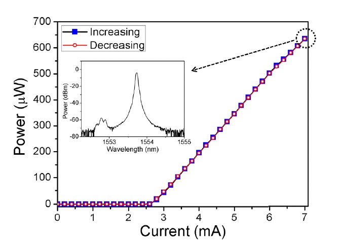
Figure 1 shows a light-current (L-I) curve of one VCSEL with its output powers measured from its pigtailed singlemode fiber (SMF) end at a room temperature of 21±0.3℃. The total output power was linearly increased when its bias current was increased above the threshold current of 2.7 mA. The inset of Fig. 1 indicates the measured optical spectrum of the VCSEL output at a driving current of 7 mA. A few side-mode peaks beside a strong main spectral peak from the single longitudinal- and transverse-mode VCSEL were observed at a wavelength separation of about 0.93 nm and the side mode suppression ratio was larger than 50 dB. The linewidth (full width at half maximum; FWHM) and optical power of the main peak were 0.06 nm and 635 μW, respectively.
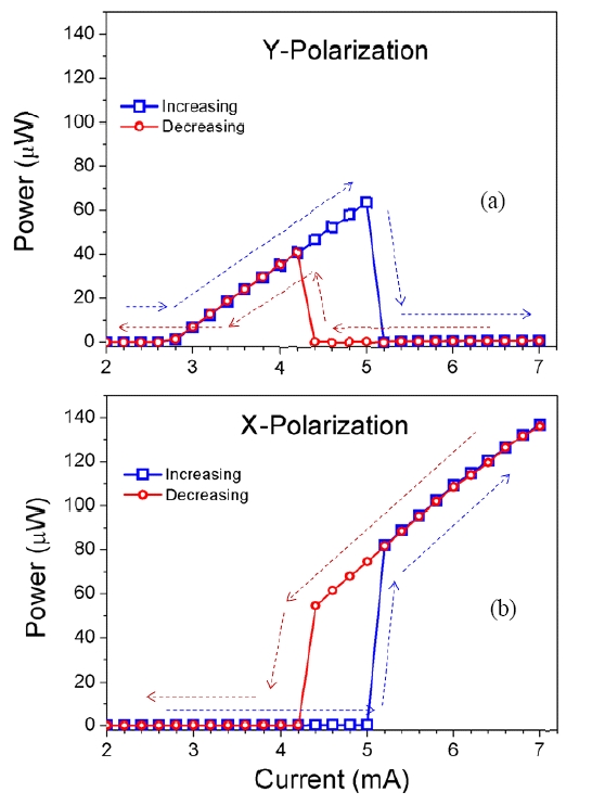
Figure 2 shows the polarization-resolved light outputs of the VCSEL versus its bias current measured with a fibertype polarization beam splitter (PBS) to separate the laser output into two polarization outputs. When the driving current
[TABLE 1.] Measured polarization switching and bistability characteristics of ten tested VCSELs
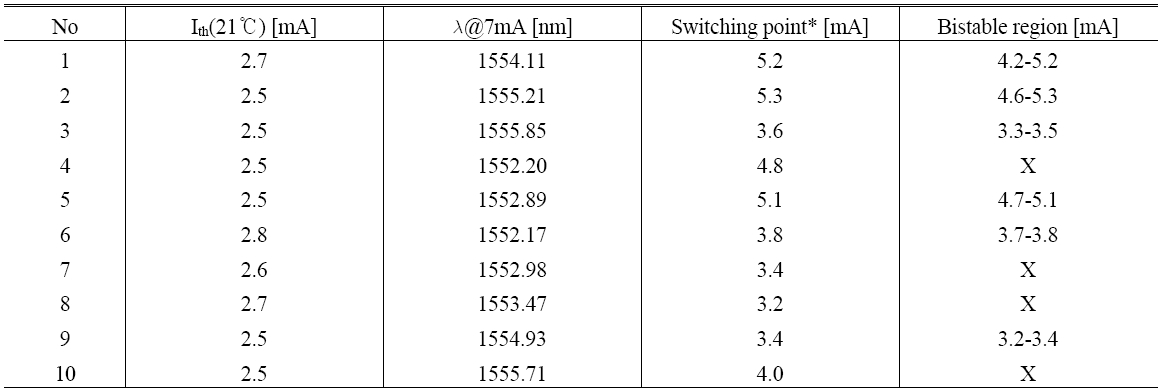
Measured polarization switching and bistability characteristics of ten tested VCSELs
was increased, the first lasing mode appeared at an initial polarization state, called as a Y-polarization mode, from the threshold current of 2.7 mA (Fig. 2(a)). The output power of this lasing mode was increased until the driving current was increased up to 5.2 mA, but the lasing mode was suddenly switched to the orthogonal polarization state, called as an X-polarization mode, at the driving currents above 5.2 mA (Fig. 2(b)). The X-polarization mode output was maintained and its output power was increased as the current was further increased. When the driving current was decreased from a high bias current, the X-polarization mode output was maintained until it reached 4.2 mA, and then switched back to the Y-polarization mode output below 4.2 mA. Similar behaviors were reported by other groups for the 835 nm and 1550 nm bistable VCSELs [15, 13]. It was observed from our measurements that this polarization bistability property of the VCSEL with change of the driving current varied from chip to chip dependent on the VCSEL chip’s condition such as strain, gain-offset, uniformity and circular symmetricity during the fabrication process even within one wafer. In Table 1, the polarization bistability characteristics of ten VCSEL samples, all fabricated from a single wafer, are summarized. Polarization switching was observed at the laser output when the driving current was varied for all the tested VCSELs, but the polarization bistability was not observed for all of them.
III. All-OPTICAL FLIP-FLOP OPERATION
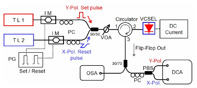
The experimental setup used for the demonstration of the polarization bistability based AOFF operation of a VCSEL is shown in Fig. 3. The VCSEL was operated at the driving current of 4.7 mA which corresponded to the center of the bistable region. Two tunable laser (TL) output beams, each of which was modulated with a Mach- Zehnder intensity modulator (IM), were used as the set
and reset pulse injection beams for the flip-flop operation of the VCSEL. The set and reset pulse beams were aligned by polarization controllers (PCs) to the Y- and X-polarization mode directions of the VCSEL, respectively. The set and reset pulses passed through a 50/50 directional coupler and then injected into the VCSEL via a variable optical attenuator (VOA) and an optical circulator. The output beam from the VCSEL passed through the same optical circulator and then through a 30/70 directional coupler. One port of the 30/70 coupler was connected to an optical spectrum analyzer (OSA, Anritsu MS9710A) for measurement of optical spectra of the VCSEL’s output and of the injection beams reflected at the mirror surface of the VCSEL. The other output port of the 30/70 coupler was connected to another PC and then to a fiber-type PBS for delivery of separated outputs of two orthogonal polarization modes. Finally, the AOFF signal was measured by a digital communication analyzer (DCA, HP 83485A) with two 20 GHz photoreceiver modules.
3.2. Results of all-optical flip-flop operation
The wavelength separation between the VCSEL outputs
at its X- and Y-polarization modes at 4.7 mA was measured to be about 0.09 nm. It was observed that the wavelength separation between the two polarization-mode outputs was the same over the entire driving current range. Thus, the wavelengths of the set and reset pulses were adjusted to 1552.35 nm and 1552.44 nm, each of which corresponded to the wavelength of the VCSEL’s Y- and X-polarization mode outputs, respectively. The intensity modulators (IMs) were driven with a delay pulse generator (PG, HP 8130A) at a repetition rate of 25 MHz with 20 ns time delay. The pulse widths of the generated optical set and reset pulses were 1.828 ns and 1.840 ns, respectively. The measured average powers of the set and reset pulse streams were also -17.9 and -16.63 dBm, respectively. The attenuation ratio of the VOA was set to 15.05 dB, and thus the injected pulse energies of the set and reset pulses into the VCSEL amounted to 10.2 and 13.6 fJ, respectively.
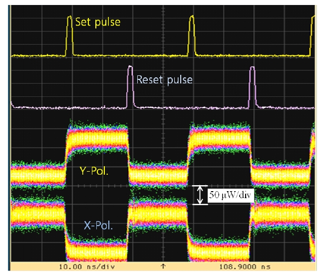
Figure 4 shows the measured pulse shapes of the injection pulses and the output patterns of the VCSEL under the AOFF operation at a switching frequency of 50 MHz. Initially, the VCSEL output was in the X-polarization direction at the bias current of 4.7 mA with the decreasing current mode as shown in Fig. 2(b). When a set pulse of the Y-polarization direction was injected into the VCSEL, the polarization of the VCSEL output was changed from X- to Y-polarization, and the switched polarization direction was maintained. Then, as a reset pulse of the X-polarization direction was injected into the VCSEL, its output polarization mode was changed back to the X-polarization direction. This process is equivalent to a conventional set and reset flip-flop operation. The average contrast ratio between the on and off states of the flip-flop output signals was about 7 dB, which was estimated from the measured signal amplitudes on the DCA. There is significant
significant room for further improvement on the operation speed and switching energy reduction by using a high speed pulse pattern generator and an optimized injection pulse width.
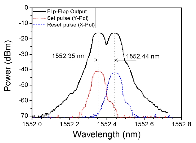
The measured optical spectra of the VCSEL’s output under the AOFF operation are shown in Fig. 5. The black solid line represents the combined output spectrum of the X- and Y-polarization modes of the VCSEL. The red dotted and blue dashed lines correspond to the optical spectra of the set and reset pulses reflected at the mirror surface of the VCSEL, respectively. These optical spectra also confirm the stable flip-flop operation. The measured wavelength difference of the two orthogonal polarization modes of the VCSEL was about 0.09 nm which was less than that of the VCSEL with no polarization bistability which was reported in ref. 12.
We have observed the polarization bistability from a conventional cylindrical-shaped 1.55-㎛ wavelength singlemode VCSELs with change of its operating current, and experimentally demonstrated the AOFF operation by utilizing the polarization bistability property with low power injection pulses. The set and reset pulses were in orthogonal polarization directions to each other, and were used to operate the AOFF operation at a switching frequency of 50 MHz. The average on-off contrast ratio of the flip-flop signals was about 7 dB. The pulse energies of the set and reset pulses were below 14 fJ. Further improvement of the AOFF operation condition can be achieved if a high-speed pulse generator is used. This polarization bistable VCSEL is very useful for applications to highspeed all-optical signal processing in future optical network systems.