Lippmann proposed integral imaging, three-dimensional(3D) display technology which shows full parallax imagesand does not need any additional equipment[1]. Recently,integral imaging systems have improved rapidly thanks tothe progress of flat panel displays such as liquid crystaldisplays (LCD), which allow the expression of full color3D moving pictures with a continuous viewing zone.
But realizing a high quality integral imaging system requires a tremendous number of pixels because of the tradeoff relationships between display resolution and viewing parameters of the integrated image. These parameters include imaging resolution, viewing angle and imaging depth[2]. In order to overcome the problem of spatial limitation of resolution, several kinds of integral imaging systems which show great improvement of viewing qualities by using multiple display devices or multiple imaging planes, were proposed [3-7],
Projection-type display is frequently used as a display device for elemental images in an integral imaging system [7-12]. For a projection-type integral imaging system, it is easy to control the size of the image and the pixel pitch, and a large size screen is achieved simply through system expansion using a multi-vision method.
An ordinary projection-type integral imaging system needs a diffuser screen, on which elemental images are located. Employing the diffuser screen incurs some disadvantages, because the resolution of the elemental image is restricted due to the diffusing grain, and optical light loss reduces the optical power efficiency of the system. Previous research, used some kind of projection-type system without diffuser screen[11, 12]. Those systems adopted a collimating lens with large aperture or a lens array with small elemental lens pitch, to test the feasibility of a system without diffuser.
The previous studies, however, did not explain the exactrelationship between the visibility and the system configuration.The relationship between the visibility and eachcomponent of the system can be a guideline for designinga projection-type integral imaging system for variousapplications.
In this paper, we analyze the relationship between theexit pupil of a projection lens system and the elementallenses, according to their geometrical shape and position.This relationship can be simply described as a fill factor,which represents the ratio of the effective imaging area tothe area of the elemental lens. Moreover, for psychologicalreasons, the configuration of the lens array, especially thesize of the elemental lens, also affects visibility. We showbriefly the relation between visibility and psychologicalfactors. Some basic experiments and results are presented.
2.1. Fill factor of central lens
The fill factor is the ratio of the effective imaging areaand the area of each individual elemental lens. In theprojection-type integral imaging system without diffuser,the visibility of the reconstructed image is greatly affectedby the fill factor. In this system, the exit pupil of theprojection lens is observed through the elemental lens, andthe image inside of the exit pupil made by the elementallens becomes the effective image. The fill factor dependson the geometry of the elemental lens and the shape of theaperture stop in the projection lens, which means we needa different formula to calculate the fill factor for differentshapes of elemental lens or of projection lens aperture stop.
The fill factor calculation can be divided into two cases.For the first case, the image of the exit pupil of the projectionlens is larger than the elemental lens; the second case isthe opposite case. If the image of the exit pupil is largerthan the elemental lens, the fill factor must be full. For theother case, we need to consider the geometry of theaperture stop and the elemental lens.
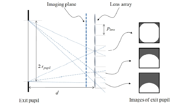
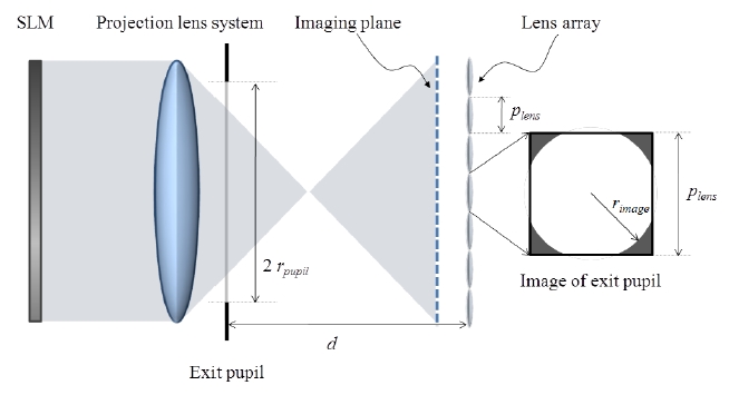
The image radius of the exit pupil of the projection lenssystem through the elemental lens, rimage, defined from thegeometry as shown in Fig. 1, can be expressed as:
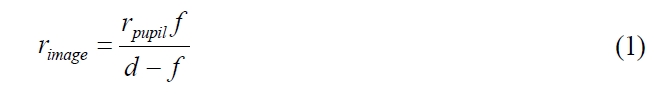
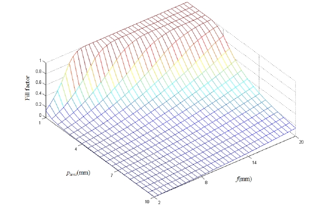
where, rpupil is the radius of the exit pupil of the projectionlens system, d is the distance between the exit pupil andthe elemental lens, and f is the focal length of theelemental lens. We assume that the projection lens has acircular exit pupil and that the elemental lens has squaregeometry. For this case, the fill factor becomes as follows:
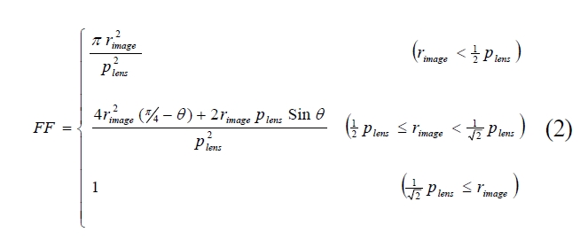
where FF is the fill factor, plens is the elemental lens pitch, and
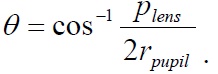
Figure 2 shows the value of fill factor as a function of the size and the focal length of the elemental lens when
As shown in Fig. 2, we can assume that the elementallens size is the most critical factor for achieving a higherfill factor because of the limitations on manufacturing an
elemental lens with short focal length and large aperturesimultaneously. Actually, in Fig. 2, the region where the fnumber, the ratio between focal length and lens pitch,becomes less than 1 is practically impossible to achieve.
The fill factor is also decided by the position of theelemental lens on the imaging plane. Because the integralimaging system is composed of a lens array, the calculationof fill factor for each elemental lens is necessary. Overallfill factor is defined by the sum of the whole effectivearea divided by the area of the display device (or the areaof the entire lens array). It is equal to the average value ofeach fill factor as shown in eq. (3).
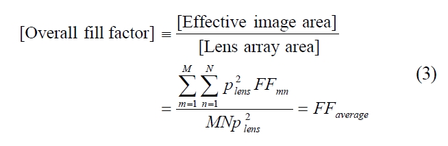
where, M and N represent the number of horizontal and vertical elemental lenses, FF
The shifting distance of the pupil image depends on themagnification and the pitch of the elemental lens. Needlessto say, it depends on the position of the elemental lens aswell. The shifting can be easily calculated from the similarityof triangles made by the exit pupil of the projection lenssystem and the image of the exit pupil through theelemental lens.
We assumed that the elemental lens which is located inthe center of the lens array has no shifting of image. Thiselemental lens is square shaped, and the elemental lensesare aligned without a gap. Then the shifting of the exitpupil image through the elemental lens which is aneighbor to the central lens is expressed as the followingeq. (4).
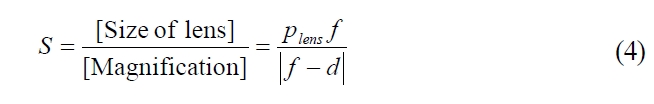
where S is the shifting distance of the exit pupil image.The lens which is located m lenses horizontally and nlenses vertically apart from the center has m times thehorizontal and n times the vertical shifting compared tothe first neighbor lenses.
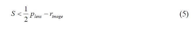
If the shift is very large so that the image is locatedbeyond the elemental lens boundary, the fill factor becomeszero. On the other hand, if the shift is small, so that itfulfills the inequality in formula (5), the fill factor remainsthe same as the fill factor of the central lens.
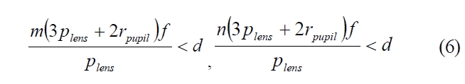
Usually, when the distance d is large enough to satisfy
the inequalities in formula (6), the shift at the outmostelemental lens does not invade the border of the elementallens, and the overall fill factor is not different from the fillfactor of the central lens.
Of course, the shift of pupil image due to the positionof the elemental image is affected by the geometric arrangementof the elemental lenses. For a more general case,such as an arbitrarily shaped aperture stop with hexagonalor triangular elemental lens configuration, the calculation ofoverall fill factor will be complex.
For this reason, we propose a computational approach toget the overall fill factor. From the definition, the overall fillfactor is defined by the ratio of the effective imaging areaand the lens array area. Getting the effective image area isquite similar to the pickup process in integral imaging.Simply, the exit pupil can be regarded as the object andthe corresponding elemental image can be considered as theobserved image in the projection-type integral imaging systemwithout diffuser. These kinds of images can be easily obtainedby the computer-generated integral imaging method. Theratio of the number of pixels inside and outside of theboundary of the exit pupil gives the overall fill factor.Using this technique, the fill factor can be calculated simplyeven if the exit pupil of the projection lens system and theelemental lens have a complicated geometry.
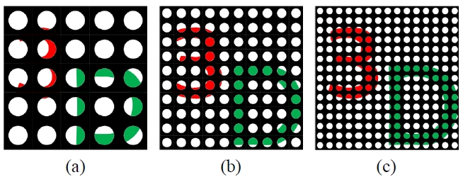
If the fill factor of the system is equal to unity, there isno difference in the visibility compared to the conventionalintegral imaging system. On the other hand, the visibility ofthe image is gradually degraded as the fill factor decreases.As shown in Fig. 4, however, even though the images havethe same fill factor, each image can show different visibilities.The image composed of a larger number of elemental imageshows better visibility. This is because of the psychologicalfactor which can be explained by Recognition-By-Component
theory(RBC theory)[13]. Although the examples shown in Fig. 4 are two-dimensional images, which are viewpoint independent, RBC theory can be directly applied in 3D images of the integral imaging system[14].
According to RBC theory, a person recognizes the objectas a combination of simple three-dimensional objects calledgeons(geometrical icons). Each geon has simple characteristics,for example the collinearity of line or the terminationof curves at a common point. And those characteristics discriminatethe geons from other geons. RBC theory statesthat if the geons of an object and the arrangement of theparts can be perceived, the whole object can be identifiedeven when the images are occluded or degraded.
Because the geons are very simple objects, the cluesthrough small apertures are enough to allow recognition ofgeons. Consequently, a lens array that consists of a largenumber of elemental lenses has more chance to show theclues for geons, resulting in better visibility. Besides, a smallerelemental lens provides a higher fill factor according tothe analysis of section II. However, if the lens pitch or thesize of the exit pupil is reduced under the pixel pitch ofthe elemental images, the system operates as if it is operatedin a focused mode of a conventional integral imaging system.In a focused mode, the number of elemental lenses isidentical to the number of 3D image pixels and the imagerecognition process becomes very similar to the case for2D images.
In order to compare the quality of the systems in a quantitativemanner, we express the total number of pixels interms of the number of lens in an array and the fill factor,which will provide the most accurate criterion for comparisonbetween systems. The total number of pixels is givenby eq. (7).
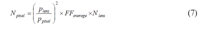
where, Npixel refers to the total number of pixels, ppixel is a pixel pitch of the display device, and Nlens stands for the total number of elemental lenses in a lens array. The first term on the right side stands for pixel density which is related to the expression of 2D texture resolution of the image, while the fill factor and total number of lenses are important for recognition of 3D objects. Equation 7 also implies the trade-off relationship between texture quality and object recognition.
In addition to the configurations of the lens array, thevisibility also depends on the condition of the observer orthe contents of the reconstructed image. Especially when theobserver or the reconstructed image is in motion, the chanceof exposing the clues of geons increases.
Consequently, the visibility of an integrated image is greatly affected by the relative size of objects compared to the lens pitch of the elemental lens, because the opportunity for perceiving geons is decided by the number of elemental lenses.
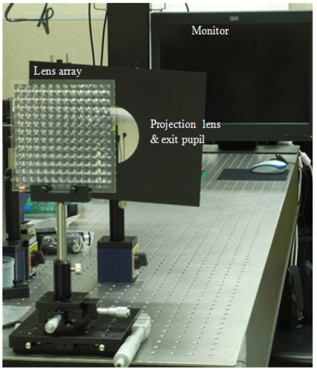
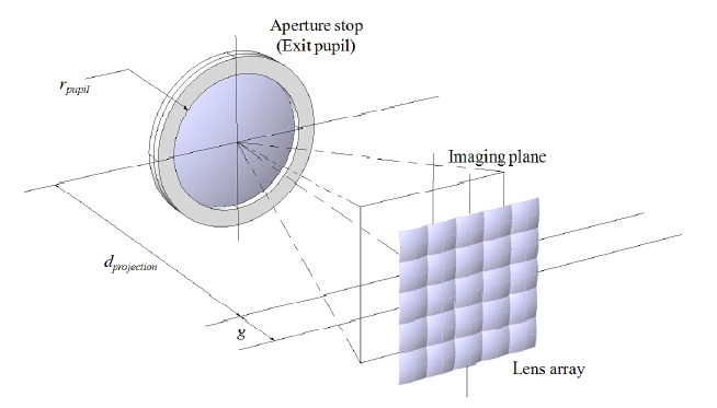
We compared the experimental results of three differentlens arrays with and without the diffuser in order to testour analysis. Figure 5 shows the schematic diagram of theexperimental setup. The distance d between exit pupil andlens array is the sum of the projection distance, dprojectionand the gap, g between imaging plane and lens array. Theprojection distance depends on the specification of theprojection lens, and the gap is mainly affected by the focallength of the elemental lens.
In the experiment, we set the projection distance muchlonger than the focal length of the elemental lens in orderto keep the shift small. Therefore, we can directly calculatethe overall fill factor from the given specifications of system.Besides, with small shifting, we can adjust the systemsetting to get the desired fill factor without complicatedcalculation.
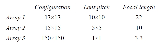
We use the typical LCD monitor with luminance of 200cd/m2. And, we adopt a single biconvex lens as a projectionlens for simplicity. We put the aperture stop in front ofthe projection lens. The aperture also plays the role of theexit pupil of the projection lens. The projection distance fromthe exit pupil of the projection lens system to the imagingscreen is around 340 mm. The size of the projected imageis 60 mm×60 mm. In the system, we adjust the radius ofaperture in the projection lens so that we can obtain thesame fill factor for the three different configurations oflens arrays. Table 1 shows the specifications of lens arraysused in the experiment.
For the experiment, we set the target fill factor at 0.3and the corresponding radii of the exit pupil of the projectionlens system for 10 mm, 5 mm and 1mm elemental
[TABLE 1.] Specifications of lens array

Specifications of lens array
lenses are 47 mm, 51 mm and 32 mm, respectively. In orderto measure and compare the fill factor with the calculatedvalue, a full white image is displayed on the monitor and apicture is taken from the position of observer. A thresholdfilter is applied to the picture for easier calculation of fillfactor. By counting the white pixels, the fill factor can beobtained. Using this method, for a lens array with 10 mmelemental lens, the measured overall fill factor is 0.27 andthe fill factor of the central lens measures 0.30 whichverifies the analysis of Section 2. The small degradation inoverall fill factor is due to the shift at the outer elementallenses, as mentioned before. The shift of a marginal lensis 3.98 mm both horizontally and vertically. Similarly, fora lens array with 5 mm and 1 mm elemental lens, the fillfactors of the central lens are 0.29 and 0.30, while overallfill factors measure 0.27 and 0.25. The shifts at themarginal lenses are 1.82mm and 0.58 mm, respectively.
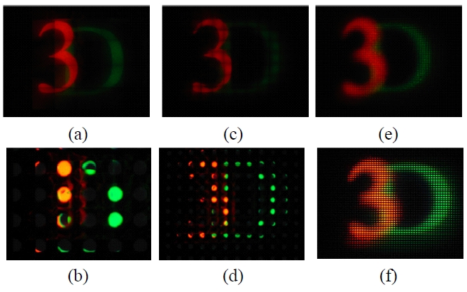
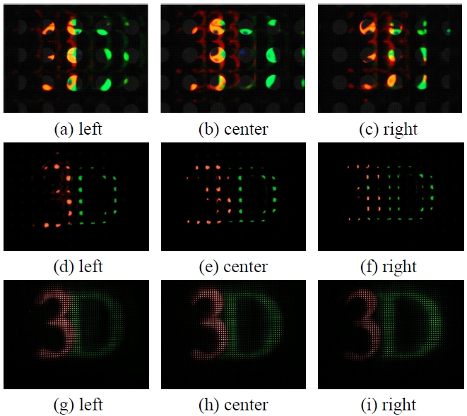
The objects of letter ‘3’ and ‘D’ were located in thedepth plane of -20 mm and -50mm from the lens array,respectively. Both letters were integrated in the virtualregion. Figure 6 shows the experimental system.
Figure 7 shows the reconstructed image for each case. There are some problems in recognizing letters in the system with the 10mm lens array, as shown in Fig. 7. (a), (b) and (c), and the parallax is hard to perceive. Besides, the aberration of the projection lens degrades the image quality. The reconstructed images of the 5mm lens array system shown in Fig. 7. (d), (e) and (f) provide higher
visibility than those of the 10mm system, but they still show degraded images and poor parallax. On the other hand, there is no problem in recognizing the letters in the 1mm lens array system as shown in Fig. 7. (g), (h) and (i). Both letters are clear and the parallax is naturally perceived. Figure 8 shows the integrated images of the projectiontype integral imaging systems with diffuser compared with the systems without diffuser. For the 1mm lens array, as shown in Fig. 8, the elemental lens size has little effect on the visibility of the system with and without diffuser
In addition,, as we expected, the system without diffusershows much brighter images, as shown in Fig. 8. We takethe pictures with the same camera settings in order tocompare the relative brightness of system.
We have reported a method of evaluating the visibilityof reconstructed images in a projection-type integral imagingsystem without diffuser in terms of the fill factor. If thelens pitch is small enough, the system shows high fill factorand a diffuser is not required. The system without diffusercan improve the optical power efficiency and can solve theproblem of restriction in resolution due to the diffusinggrain. Also, it provides good image visibility in terms ofpsychological factors.
However, the pixel number per an elemental lens areadetermines the 3D effect of the integrated image. Moreover,the diffraction noise which is incurred by small sized lensescan degrade the reconstructed image. Therefore, the elementallens cannot be reduced below a certain size. Further studyfor the optimization of the elemental lens size to considerthese conditions are necessary and will be performed.
We believe that the proposed analysis can be helpful fordesigning a projection-type integral imaging system withoutdiffuser as well as other 3D display system applications.