Widely tunable laser diodes are essential ingredients as light sources for various applications such as wavelength division multiplexing systems, all-optical networks, bio-sensors, and optical coherence tomography [1-5]. For a long time, tunable laser diodes have usually been designed and fabricated based on grating structures, but there are some difficulties in mass production because fabrication is complex. To bypass these difficulties, several research groups have been investigating tunable laser diodes based on ring resonators [6-8], which are quite attractive due to their compact size, easy integration with other components, and the elimination of need for a grating structure. Recently a coupled-ring reflector (CRR) is proposed for a widely tunable wavelengthselective device [9]. The CRR consists of two coupled ring resonators and a straight waveguide coupled to both rings. It can be a substitute for a distributed Bragg reflector (DBR) or a sampled grating DBR employed in tunable laser diodes.
In this paper, we report on design, fabrication, and demonstration of widely tunable CRR laser diodes. Especially, square ring resonators with total internal reflection (TIR) mirrors and deeply etched multi-mode interference (MMI) couplers are adopted to realize a compact size for the CRR laser diodes. Offset quantum well techniques are employed to integrate semiconductor optical amplifiers (SOAs) with passive waveguides [10]. The other processes for the fabrication of the CRR laser diodes are compatible with those for conventional ridge or rib laser diodes.
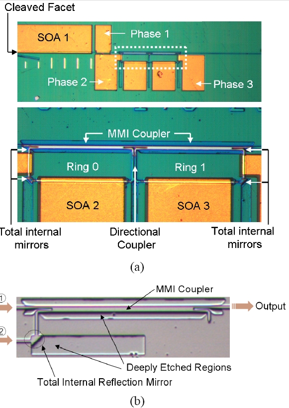
Fig. 1(a) is a microphotograph of the fabricated CRR laser diode. Epitaxial layers of the wafer are designed as follows. The core of the passive waveguides is a 0.35 ㎛thick quaternary material with a photoluminescence peak at 1.4 ㎛. It is grown on a 1.8-㎛-thick n-InP layer on an n-InP substrate. On top of the core layer, 10nm undoped InP is grown. Then a 0.1-㎛-thick multi-quantum-well (MQW) layer is grown on top of the passive core. MQW has seven wells and eight barriers. The well and barrier widths are 7.5 and 8 nm, respectively. The active MQW layer beyond the SOA regions is etched out, and a 1.8-μ m-thick p-InP layer followed by a 0.1-㎛-thick p-InGaAs contact layer are over-grown. Then the passive and active waveguides are formed with the over-grown wafer. This approach is a so-called offset quantum technology and is described in detail in the reference [11].
The laser diode consists of three SOAs and two square ring resonators which are coupled with each other and with a straight bus waveguide. The couplings between the straight bus waveguide and ring resonators are achieved using deeply etched 3-dB MMI couplers, and the coupling between ring resonators using a directional coupler. For minimizing the length of the MMI couplers, the region outside the waveguide pattern is deeply etched. The top view of the deeply etched MMI coupler and the total internal reflectors separately fabricated on the same wafer are shown in Fig. 1(b). The width and length of the MMI coupler are 6 ㎛ and 172 ㎛, respectively. Because the width of the passive waveguide is 3 ㎛ and that of the input/output waveguides to/from the MMI couplers is 1.5 ㎛, a taper waveguide is inserted for the purpose of reducing the coupling loss from the waveguide to the MMI coupler. The deeply etched taper waveguide has width varying from 1.5 ㎛ to 3 ㎛ over the length of 15 ㎛. For this design, the coupling loss is calculated to be about 0.11 dB by a BPM simulation. Effective refractive index variations due to the error of ridge waveguide height are prevented through deep etching into the bottom cladding layer so that the deeply etched MMI coupler provides the designed 3-dB coupling characteristic consistently. When input 1 is excited with an optical source, -31.2 dBm is observed from output denoted in Fig. 1(b). When Input 2 is excited, -34.1 dBm is observed from the output. The output from a straight waveguide of the same length is observed to be about -28.4 dBm. Considering about 3 dB loss from two TIR mirrors for the case of the excitation into Input 2, balanced 3 dB coupling with almost no excess loss is expected from the fabricated MMI coupler. For the case of a ring resonator with a circular waveguide, it is difficult to reduce device size due to bending loss of the resonator. The laser diode in this paper consists of square ring resonators with total internal mirrors for decreasing device size.
The MMI couplers and TIR mirrors are fabricated using a self-aligned process in which shallowly etched waveguide region, deeply etched mirror facets, and MMI sections are fabricated using a single mask pattern [11-12]. In order to make vertically etched mirror facets and to reduce their sidewall roughness, dry etching processes are carried out using an ICP RIE (inductively coupled plasma reactive ion etch) dry etching system (Oxford Instrument System 100) with a ICP power of 1500W, an RF power of 150W, and a mixture gas source (Cl2, CH4, H2). The loss on the fabricated mirror facets is measured to be about 1.55 dB.
The perimeter of Ring 0 is 560 ㎛ and that of Ring 1 is 4 % longer than that of Ring 0. To prevent the reflection from the cleaved facet, the waveguide near the right facet is tilted by about 8 degrees. Using offset quantum well technology, the CRR is monolithically integrated with SOAs in the ring resonators (SOA 2 and 3) for loss compensation and in the straight waveguide (SOA 1) for the lasing action [10]. The length of SOA 1 is about 700 ㎛ and the total length of the device is about 1.7 mm. The phase control electrodes (Phase 1, 2, and 3) are also formed between SOA 1 and the CRR, and in the ring resonators. The refractive index of these regions can be changed through a plasma effect by current injection. The phase control electrode 1 plays a role of controlling the cavity mode of the CRR laser diode and the phase control electrodes 2, 3 are used in controlling the resonance wavelength of each ring.
The wave created in the SOA 1 is coupled to Ring 0, and then the clockwise wave in Ring 0 is coupled to a counter-clockwise wave in Ring 1, and finally the wave is coupled to the backward wave in the straight waveguide. Because the perimeters are slightly different from each other, the free spectral ranges (FSR) of these rings are slightly different and resonance wavelengths of these two rings are misaligned except at certain wavelengths. For this case, strong reflection occurs at the wavelengths where both the rings are resonant and the laser diode is forced to lase at these wavelengths. Due to this vernier effect, tuning range enhancement is obtained, with a value of the inverse of the relative perimeter difference between the two rings. Then, the tuning range of the CRR is a free spectral range times the tuning enhancement factor [13]. Since the free spectral range is about 1.1 nm and the tuning enhancement factor is 25, an overall tuning range of about 28 nm is expected in the designed CRR laser diode.
The reflection spectrum of the CRR is strongly influenced by the coupling coefficient. The condition of coupling coefficient satisfying the single reflection peak (flat-top) at the resonant wavelength is given by [9]
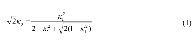
where κ1 and κ0 are bus-ring and ring-ring coupling ratios, respectively. Because the 3-dB MMI couplers are adopted for the bus-ring coupling, the bus-ring coupling ratio is 0.707 and thus the ring-ring coupling ratio must be 0.14 according to (1). This value can be achieved through a proper design of the directional coupler between the two rings. The bus-ring coupling ratio of 0.707 is achieved using a multimode interference coupler whose width and length are 6 ㎛ and 172 ㎛, respectively. The gap and length of the directional coupler are designed to be 1.6 μ m and 60 ㎛, respectively, to provide the coupling ratio of 0.17.
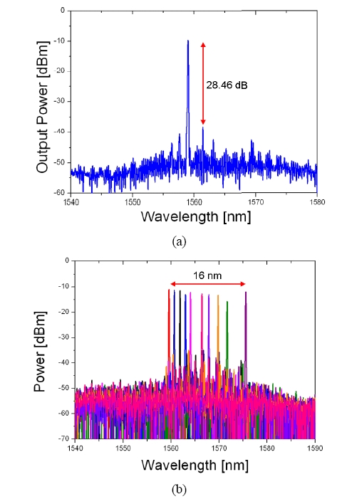
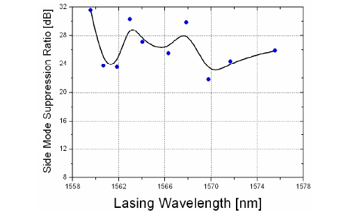
The lasing spectrum of the fabricated CRR laser diode is shown in Fig. 2(a). The injection current into the SOA 1 and that into the loss compensation regions in two rings (SOA 2, 3) are 140 mA and 10 mA respectively, and no phase control current is applied. The spectrum shows that the coupled ring reflector laser diode is single-moded at 1559 nm with about 28 dB side mode suppression ratio (SMSR). The refractive indices in each phase control region in the rings are adjusted by current injection in one ring while no current is injected into the other ring. Concurrently, the currents into SOA 2, 3 and Phase 1 are adjusted for the purpose of maintaining maximum SMSR, and the lasing wavelength is tuned by multiples of a free spectral range of ring resonators. The superimposed lasing spectra of the laser diode with SMSR exceeding 20dB are shown in Fig. 2(b), which shows that the lasing wavelength can be tuned from 1559.5 nm to 1575.2 nm. The output power is measured to be higher than -5 dBm. Fig. 3 shows the measured SMSR as a function of the lasing wavelength. The measured threshold current is about 130 mA. The characteristics of the CRR laser diode are measured when the currents into SOA 2, 3 are larger than 10 mA. In this case, the SMSR is worsened due to the possible refractive index changes. It is also believed that the injection current level larger than 10 mA does not bring adequate compensation of loss in the ring resonator possibly due to the gain saturation.
Lower output powers and narrower tuning range are observed in comparison with the simulation results [14]. We suppose that these discrepancies are caused by low reflectivity and reduced contrast between the main reflection peak and side peaks of the CRR due to high absorption loss in the CRR waveguides, mirror loss, and inaccurate coupling ratio of the directional coupler due to possible etching depth errors in the formation of shallow waveguides. In this device, the bandgap wavelength of the passive waveguide core is 1.4 ㎛, and it is quite close to that of the active region (1.55 ㎛) to provide high reflectivity in the vicinity of the gain peak. Therefore the lasing wavelength tends to be longer than the gain peak wavelength of the active region, which seems to limit the tuning range. Though the SOA 2 and 3 monolithically integrated in the ring resonators play a role of loss compensation, they do not seem to provide sufficient gain to compensate the absorption loss in the passive waveguide. If the bandgap wavelength of the passive waveguide is shifted to shorter wavelength through a proper epitaxial design and growth, it is expected that the absorption loss could be reduced and then the tuning and lasing characteristics could be improved. The additional loss due to mirror facets in resonators needs to be decreased further through a more controlled etching process to obtain vertical and smooth facets [11].
In this paper, we report on the fabrication and characterization of a coupled ring reflector laser diode composed of square ring resonators with TIR mirrors integrated with SOAs. The laser diode can be tuned by injection currents into phase regions and its tuning range is measured to be as wide as 16 nm with SMSR over 20 dB and output power over -5 dBm. To compete with tunable laser diodes based on gratings, the performance of this device needs to be further improved through optimum design and carefully controlled fabrication conditions.