Quadrature Wilkinson power dividers have typically been adopted to realize balanced amplifiers and as image-rejection mixers in microwave circuit design. Structurally, quadrature Wilkinson power dividers are designed to integrated the Wilkinson power divider with a 90° phase-adjusting circuit. Numerous studies have been devoted to the design of these 90° phase-adjusting circuits [1–5]. Low-pass and high-pass filters were implemented with Wilkinson power divider to obtain a 90° phase difference between output ports [1]. The phase compensated transmission lines [2] or the all-pass active filters [3] were introduced for achieving wideband 90° phase difference. The metamaterialbased quadrature power divider has also been reported for realizing broad-bandwidth [4]. On the other hand, a substrate integrated waveguide (SIW)-based quadrature power divider using lumped elements has also been described [5].
The SIW is one of the planar waveguides, constructed with two parallel via fences or bar vias between metal layers at the top and the bottom of the printed circuit board (PCB). The SIW has two distinct merits: it enables the taking of traditional waveguide components to PCB-based planar components, and reduces the hollow waveguide size by using the dielectric constant of the PCB [5–7]. However, the reported SIW quadrature power divider [5] has a narrow band with a 90° phase difference because the lumped elements on the transition structure have limitations with respect to their ability to achieve the broadband 90° phase difference.
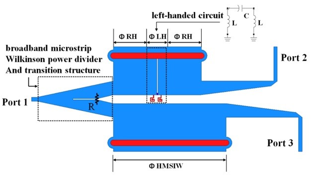
In this paper, we propose a broadband half-mode SIW (HMSIW) quadrature Wilkinson power divider using composite right and left-handed (CRLH) transmission line (TL). The HMSIW is one of the SIW, and is half size of the SIW. The proposed CRLH-HMSIW is conducted with two lumped shunt inductors and a surface mount technology (SMT) series capacitor on the edge of the HMSIW, and the broadband Wilkinson power divider [8] is integrated with the transition structure.
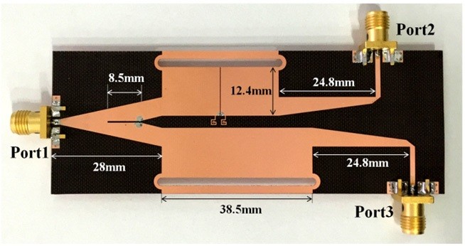
Fig. 1 presents the proposed HMSIW quadrature power divider using CRLH-HMSIW. The SIW or HMSIW requires a transition circuit for use with other planar circuit devices based on microstrip (MS) or coplanar waveguide (CPW) [5,6]. The broadband MS Wilkinson power divider was designed and integrated with the transition structure between MS and HMSIW for achieving a highly integrated SIW circuit. To obtain broad-bandwidth, a tapered line was adopted for input/output matching of the power divider [9]. The fundamental mode of SIW is the TE1,0 mode and its higher order mode starts with the TE2,0 mode. However, the fundamental mode of the HMSIW is the TE0.5,0 mode, with the first higher order being the TE1.5,0 mode. The TE1.5,0 mode has a frequency range that is three times that of the fundamental mode; therefore, the bandwidth for HMSIW is wider than that of SIW [9].
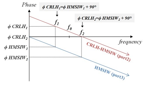
The proposed power divider splits the power to the phase adjust circuit, the proposed CRLH-HMSIW and the HMSIW. Fig. 2 shows the phase responses of the proposed CRLH-HMSIW and the HMSIW. The proposed CRLH-HMSIW phase response was designed to have 90° synchronization with the HMSIW from
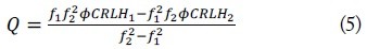
To design the proposed structure, the phase response between


where
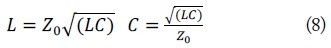
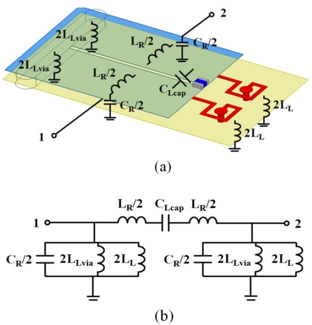
Fig. 3(a) and (b) refer to the unit cell of the proposed CRLH-HMSIW and the equivalent circuit model of the unit cell. The LH section of the proposed CRLH-HMSIW has a controllable shunt inductor,

where
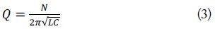
After solving the formulas (1) and (2), the

The design procedures can be summarized as follows:


where

The demonstrated HMSIW quadrature power divider is shown in Fig. 4. Three target frequencies,
The demonstration was designed on a Taconic TLX-8 substrate (dielectric constant = 2.55, height = 0.508 mm). The HMSIW in the proposed structure has characteristic impedance (
To realize the CRLH-HMSIW, two PCB-embedded inductors and a Murata 0201-sized SMT capacitor are utilized. This demonstration implements the calculated design parameters from Section II with the LH section parameters being
The 50-Ω chip resistor on the input transition structure was attached for obtaining isolation between the output ports [8].
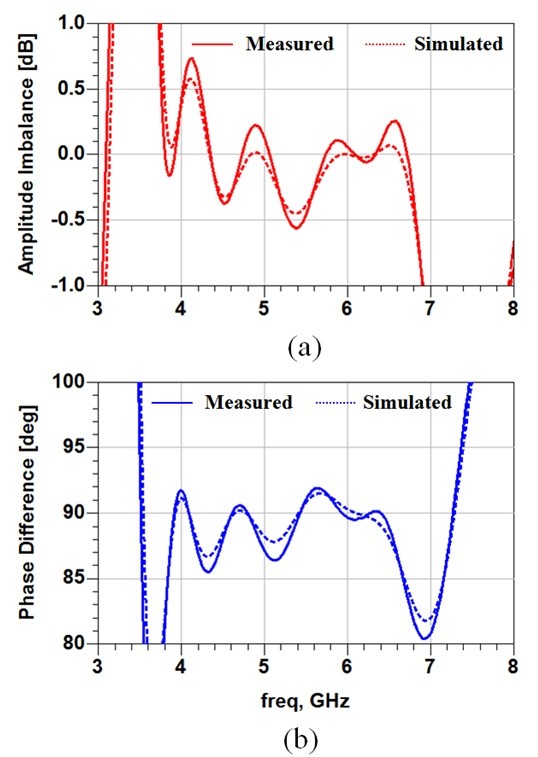
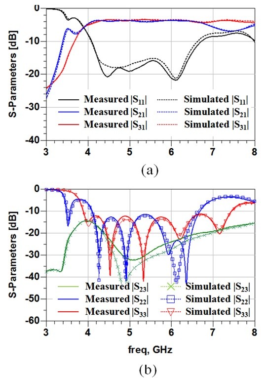
For measurement, the transition structures between HMSIW and MS were utilized, and the SMA connectors were soldered on the edge of the MS line. The measured
The performance comparison between the conventional SIW quadrature power divider [5] and the proposed HMSIW quadrature power divider is shown in Table 1. The proposed structure has more wide-bandwidth than [5], with better isolation performance.
[Table 1.] Performance comparison
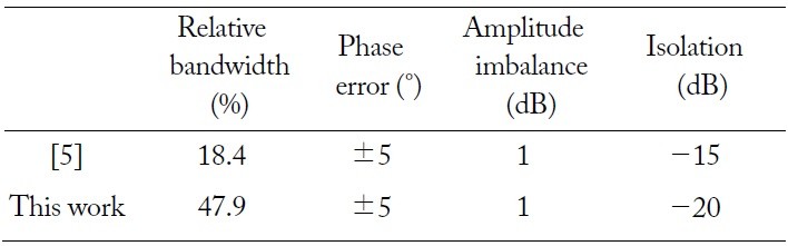
Performance comparison
In this paper, a broadband HMSIW quadrature Wilkinson power divider using CRLH TL is presented. The proposed structure shows good amplitude imbalance, within 1 dB, 90° phase difference, and excellent isolation performance between output ports. The measurement results show good agreements with the simulation.