Since its approval for use in communications by the Federal Communications Commission in 2002, the ultra-wideband (UWB) has received substantial attention from both the academic and industrial sectors [1]. UWB applications have become the focus of short range, high speed wireless communication because of its many advantages-high speed data rate, high precision ranging, low power consumption, and great capacity. Research activity on UWB systems continues to grow rapidly, and many different prototypes of UWB antennas have been proposed and developed [2–4]. The antenna plays an important role as a key component that determines the RF performance of the end-product. Therefore, the increasing popularity of UWB communications has created a need for a UWB antenna with a low profile, low weight, low cost, easy fabrication, the ability to be flush-mounted, and simplicity in structure. Conversely, the frequency range for UWB systems will cause interference with existing narrowband wireless communication systems. As an example, the wireless local area network for IEEE 802.11a operates at 5.15–5.35 GHz and 5.725–5.725 GHz; while the IEEE 802.16 system operates at 3.3–3.7 GHz.
Therefore, compact UWB antennas with dual band-notched characteristics capable of avoiding any potential interference are required. Recently, a number of band-notched UWB antennas have been discussed, and several methods have been used to create antennas with band notched characteristics [5–13]. In particular, pot-shaped patch antennas for wideband application have been studied [14, 15]. Pot-shaped UWB antennas [14] and dual band notched pot-shaped UWB antennas [15] have been researched.
In this paper, a novel dual band-notched UWB antenna is proposed with a band-notched design process. The proposed antenna is fed by a microstrip feed line. By inserting a U-shaped slot and an inverted U-shaped slot into the pot-shaped radiator and tuning the relevant parameters, two notched band applications are achieved. The dual band-notched antenna is fabricated and experimentally verified. A parametric study is performed by observing the effect of the different geometrical parameters on the performance of the proposed antenna. The measured gain and radiation patterns are presented.
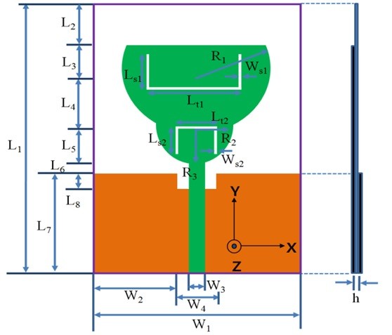
Fig. 1 shows the geometrical configuration of the proposed antenna. The antenna is designed and fabricated on a RF4 substrate with a dielectric constant and dielectric loss tangent of 4.4 and 0.02, respectively, and a thickness of 1.0 mm. The total size of the substrate and the ground plane of the proposed antenna are 25.0 mm × 39.5 mm (
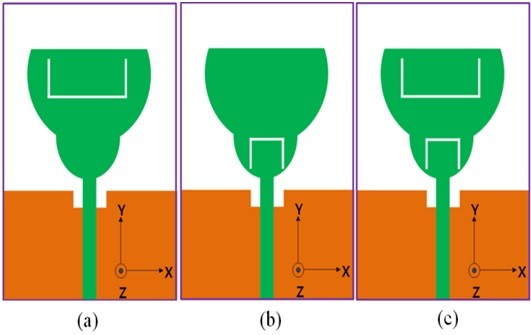
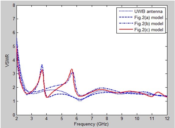
The geometry for a U-shaped slot in the pot-shaped patch in order to obtain 3.5 GHz band-notched characteristics, an inverted U-shaped slot in in the pot-shaped patch in order to obtain 5.5 GHz band-notched characteristics, and the proposed antenna structure are shown in Fig. 2. Voltage standing wave ratio (VSWR) characteristics for the structures shown in Fig. 2 are compared in Fig. 3. As shown in Fig. 3, we insert a U-shaped slot and an inverted U-shaped slot in the pot-shaped patch, and a dual band-notched function can be achieved.
[Fig. 3.] Simulated VSWR characteristics for the evolution of the proposed antennas shown in Fig. 2.
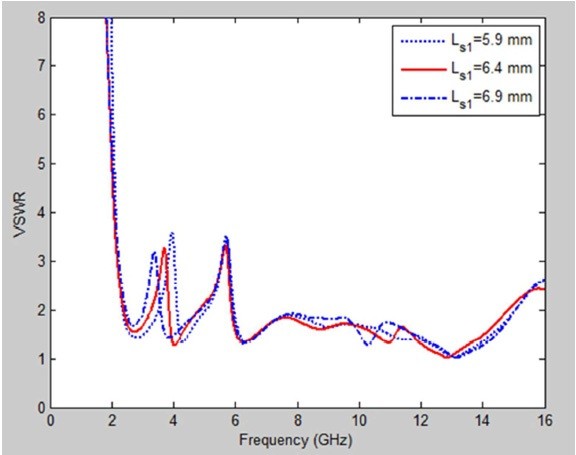
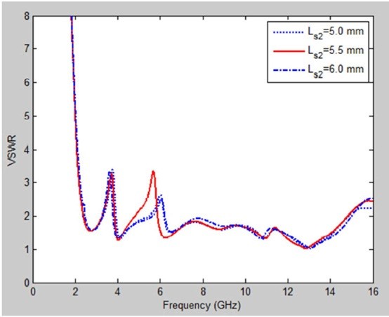
The design of the proposed antenna is in accordance with the described guidelines followed for optimization with the commercially available software Ansoft HFSS version 1.0 (ANSYS Inc., Canonsburg, PA, USA)-a full-wave commercial EM software capable of simulating a finite substrate and a finite ground structure. Parameter studies are conducted to provide more detailed information about the antenna and optimization. By adjusting the lengths, widths, and locations of the U-shaped slot and the inverted U-shaped slot, we can obtain the optimized antenna dimensions. From the simulated results, the VSWR curves for the proposed antenna with various parameters
The values of the design parameters shown in Fig. 1 were calculated using the optimized Ansoft HFSS. Thus, the dimensions of the proposed antenna were set as follows:
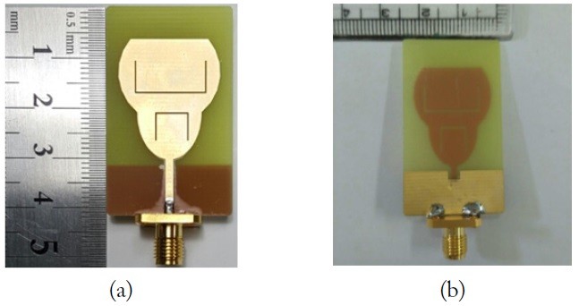
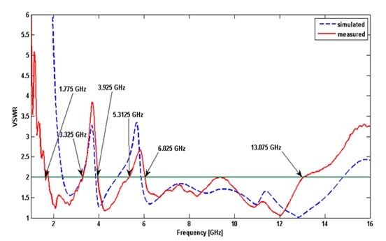
A photograph of the fabricated proposed antenna with dual band-notched characteristics is illustrated in Fig. 6. Fig. 6(a) and (b) show the front and back view of the fabricated antenna, respectively. Fig. 7 plots the simulated and measured VSWR as a function of frequency for the proposed antenna. The VSWR of the proposed antenna is measured using the Anritsu MS4644A vector network analyzer. The measurement demonstrates that the proposed antenna exhibits dual-notched frequency bands of 3.325.2–3.925 GHz and 5.3125–6.025 GHz, while maintaining a wideband performance from 1.775.5 to 13.075 GHz for VSWR ≤ 2, covering the entire UWB frequency band (3.1–10.3 GHz).
[Fig. 6.] Prototype of the proposed dual band notched UWB antenna. (a) front view and (b) back view.

The measured notched band shows an upwards shift from the simulated results. The difference is mainly accounted for by the effect of the SMA and possible numerical errors. As the simulation used a waveguide port, and since an SMA connector was used for the measurement, a difference appeared between the measurement and simulation results.
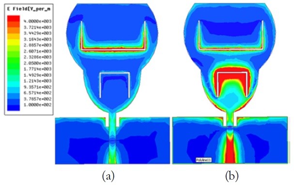
To better understand the band-notched behavior of the antenna, the simulated surface current distributions on the proposed antenna are presented and discussed. Fig. 8 depicts the current distribution of the proposed antenna at 3.66 and 5.68 GHz. It is seen that dense currents are distributed around the U-shaped slots at notch frequencies of 3.66 and 5.68 GHz, which may cause impedance variations in forming the notch bands. At the operating frequency of 3.66 and 5.68 GHz, the current distributions are mostly concentrated on the U-shaped slot and the inverted U-shaped slot in the potshaped antenna, causing the notched bands.
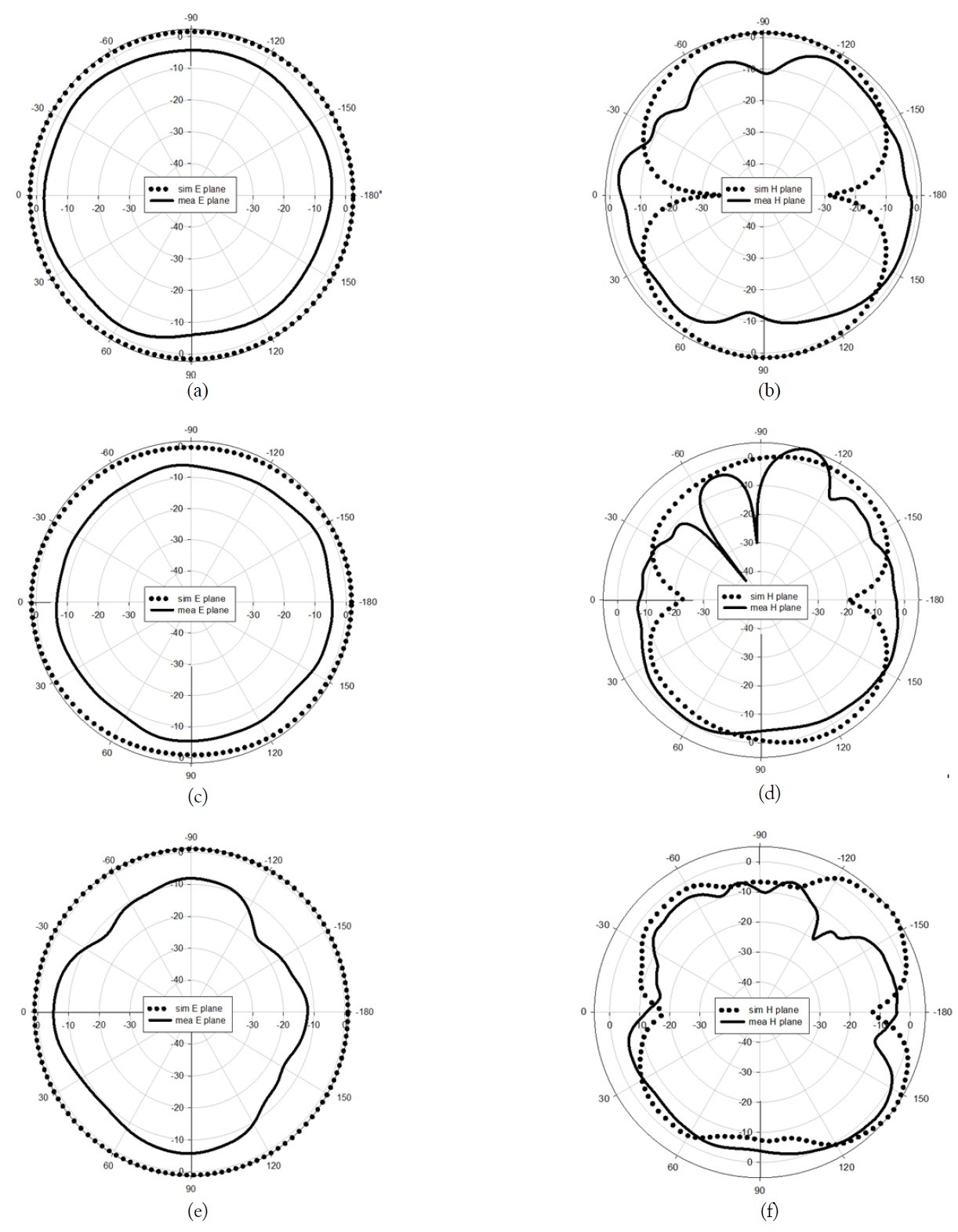
The radiation characteristics of the proposed antenna are measured. All the results are tested using ACE. The measured far-field radiation pattern of the proposed antenna at frequencies of 3.1 GHz, 6.1 GHz, and 9.1 GHz in the two principles-E plane (xz-plane) and H plane (yz-plane)-are shown in Fig. 9. It is seen that the radiation patterns in the E-plane are bidirectional radiation for operating at all frequencies, and the radiation patterns in the H-plane as somewhat omni-directional.
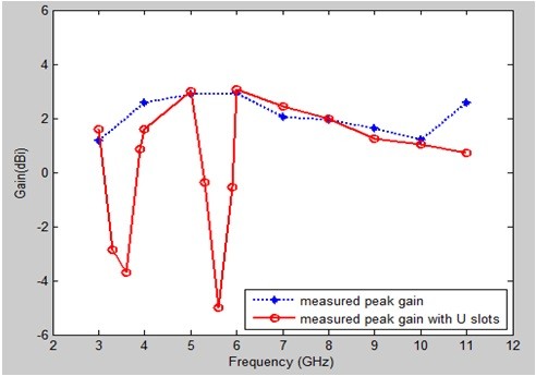
Furthermore, Fig. 10 presents the measured peak gain variations against the frequency of the proposed antenna with and without the U slots on the radiating patch. As observed, a sharp gain reduction is obtained at the 3.5 GHz band and 5.5 GHz band. The proposed antenna successfully performed with the rejection in 3.5 and 5.5 GHz notched bands. The gains range from 1.183 to 5.8 dBi over the operating band of 3.1–10.6 GHz, except the 3.3–3.7 GHz band with the lowest point of -3.693 dBi at 3.6 GHz and the 5–6 GHz band with the lowest point of -4.988 dBi at 5.6 GHz.
In this article, a simple pot-shaped planar UWB antenna with dual band-notched characteristics has been presented, and its characteristics are investigated. By adjusting the lengths, widths, and locations of a U-shaped slot and an inverted U-shaped slot, we can obtain the optimized antenna dimensions. Furthermore, the results of the studies on the simulated surface current distributions at the dual bandnotched frequencies are discussed herein. The fabricated antenna has a frequency band of 1.775 to over 13.075 GHz with two rejection bands of 3.325.2–3.925 GHz and 5.3125–6.025 GHz, while maintaining a wideband performance from 1.775.5 to 13.075 GHz for VSWR ≤ 2, covering the entire UWB frequency band (3.1–10.3 GHz). The proposed UWB antenna also exhibits omni-directionality in the H-plane and a monopole-like pattern in the E-plane. The gains range from 1.183 to 5.8 dBi over the operating band of 3.1–10.6 GHz, except the 3.3–3.7 GHz band with the lowest point of -3.693 dBi at 3.6 GHz and the 5–6 GHz band with the lowest point of -4.988 dBi at 5.6 GHz. The compact size and viable antenna characteristics of the presented antenna make it appropriate for UWB system applications.