Ordered porous materials are of great scientific and technological interest due to their ability to interact with atoms, ions, and molecules not only at their outer surfaces, but also throughout their bulk [1]. Amongst the various chemical families of ordered porous materials, porous carbons, a class of non-oxide porous materials, are of great importance due to their applications in the adsorption and purification of gases and liquids. They also serve as supports of molecules for sensing or as components of electrodes [1-3]. Most porous carbons are primarily microporous (pore widths less than 2 nm [4]) in powder form, and these are well-suited to many applications involving small molecules, such as molecular sieving, adsorption, and catalysis [5]. However, there are a number of other potential uses in which the presence of mesopores (pore widths 2–50 nm [4]) and, simultaneously, a monolithic material instead of a powder, are preferable. Mesoporous carbon can be obtained by hard-template synthesis where silica or silica-alumina materials are used as template [6]. However, more recently, the use of soft-template methodologies where, for instance, surfactant molecules are used as templates, has been successfully employed [6]. For mesoporous carbon powders obtained by the hard or the soft-templated methods, a large number of studies exist in the literature, including reviews considering their preparation methodologies and their characterization [1,6-8]. On the other hand, for monolith mesoporous carbon prepared by soft-template methodologies, just a few studies exist in the literature [9]. In the present work we prepared mesoporous carbons using a non-ionic surfactant (Pluronic F127; Sigma, USA) in a matrix of open cell polyurethane foam, so that the final carbon material has the monolithic shape of the foam matrix, but also has hierarchical porosity, with macropores from the polyurethane foam, as well as inherent meso- and micro-pores. The materials were characterized for their porosity, mechanical, and electrochemical properties.
2.1.1. Carbon powders
Before preparation of the carbon materials in the monolithic shape, the synthesis method was optimized to obtain the best porosity characteristics. The base procedure was adapted from the literature [10] and involved the previous preparation of a resol precursor from phenol and formaldehyde. During the optimization procedure it was verified that the resol precursor should not be aged, because the best results were obtained with freshly prepared resol solutions. Therefore, for the preparation of the carbon powders, resol was added with stirring to a solution of 1 g of surfactant (Pluronic F127, Sigma) in 20 cm3 of ethanol (Merck, absolute, Germany). This mixture was left to evaporate in Petri dishes at ambient temperature; then put in an oven at 100℃ for 24 h. After removal from the Petri dish this precursor was heated in a tubular oven (P 330; Nabertherm, Germany) under nitrogen flow (1.5 cm3/s) with various heating programs: the final temperatures were 350℃, 800℃, and 900℃ and the rates were 1 and 5℃/min for temperatures below and above 600℃, respectively. Table 1 presents the main differences in the experimental procedures for the various powder materials, labeled P1 to P11, namely concerning resol aging time, purity of the ethanol used in the preparation of the resol mixture, and calcination temperature.
[Table 1.] Experimental conditions and textural properties of the powder and carbon foam materials
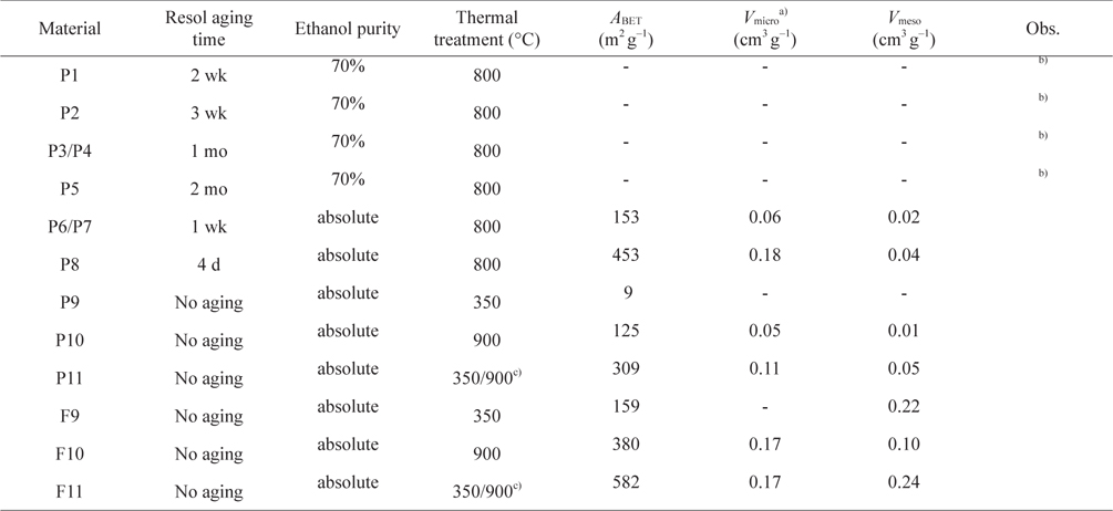
Experimental conditions and textural properties of the powder and carbon foam materials
2.1.2. Polyurethane foam templates
The polyurethane foam matrix was prepared according to a procedure previously developed by us [11] adding 48.3% of polyol (F-5521; Repsol YPF, Spain), 2.7% of distilled water, 0.3% silicone oil surfactant (B8232; Evonik Industries AG Germany), 0.4% of catalysts (DABCO 33LV; Air Products, USA), and 0.1% dibutyltin dilaurate (Merck, >97%) by weight in a 500 cm3 polyethylene flask. This mixture was homogenized by vigorous mixing with a stirrer. Then 48.3% of polymeric 4,40-methylene bisphenyl diisocyanate (MDI) (Lupranat M 50; BASF, Germany) was added to this mixture with continuous and vigorous stirring for 15 s, after which it was kept in an oven at 70℃ for 1 h. Cuboids of various dimensions were then cut to be used as matrixes for the formation of the monolithic carbon materials.
2.1.3. Carbon monoliths
For the preparation of the monoliths, the mixture of the resol and Pluronic 127 (Sigma) prepared (as described above) was poured in a cuboid (5 × 5 cm and 1 or 0.6 cm height) of polyurethane foam which was repeatedly squeezed to soak up the maximum amount of the resol/Pluronic mixture. The wet foam was left to evaporate at room temperature and then placed in an oven at 100℃ for 24 h. The optimization criteria for the powder carbon materials were used to establish the heating program in a tubular oven under nitrogen flow. The program used involved heating at a final temperature of 900℃, for 4 h, either directly, or with an intermediate step of heating at 350℃.
Nitrogen adsorption-desorption isotherms at −196℃ were made using an automated apparatus (NOVA 2200e, from Quantachrome or ASAP 2010 from Micromeritics). For each experiment, the samples (about 0.1 g each) were degassed under a pressure lower than 0.133 Pa for 3 h at 120℃ or 300℃, for the samples calcined at 350℃ or 900℃, respectively. Mesopore size distributions were calculated using a modified version of the Broekhoff-de Boer method [12]. Density was measured in a gas pycnometer (AccuPyC 1330; Micromeritics), with nitrogen at 25℃.
Scanning electron microscopy images were obtained using a SU70 (Hitachi, Tokyo, Japan), using 15 kV electron beam. The carbon foam samples could be observed directly without pretreatment. The PU foams and foams impregnated with resol were submitted to gold vapor plating for 3 min.
Fourier transform infrared spectroscopy (FTIR) spectra were obtained in a IRAffinity-1S (Shimadzu, Japan) spectrophotometer. The pH measurements for determination of the pHpzc (pH at which the material has a net zero surface charge) were made with a SympHony SP70P pH meter (VWR, USA). The assays were made by reverse mass titration following the method proposed by Noh and Schwarz [13].
Mechanical properties were assessed by compression tests performed on Z020 equipment (Zwick/Roell, Germany), with the software TestXpert V11.02 Master(Fig. S1), using a displacement speed of 0.5 mm min−1. The nominal compressive stress was calculated to be σ =
The electrical conductivity was measured with a digital multimeter (DMM4040; Tektronix, USA) in a two-point configuration. Electrochemical testing was performed using a CompactStat potentiostat (Ivium, Netherlands) in a three-electrode arrangement with the carbon foam as working electrode, a platinum counter electrode, and a saturated calomel electrode (SCE) as reference. The voltammetric response was analyzed by cyclic voltammetry using 1 mM ferrocyanide + 1 mM ferricyanide with 1 M KCl background. The potentiometric response to pH was studied using standard buffer solutions provided by Analytical (Fluka).
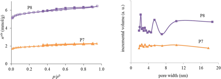
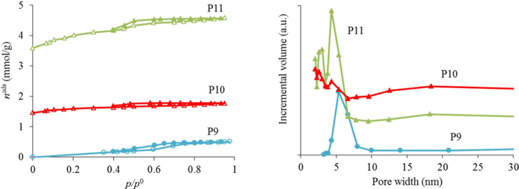
As can be seen from the results for the synthesis optimization in Table 1, it is best to use resol immediately after preparation (no aging) to generate porosity. Also, the use of absolute ethanol seems to be mandatory to obtain porosity in the samples. With a heating temperature of 800℃ (P7 and P8) it was already possible to start developing porosity but, as the nitrogen adsorption-desorption isotherms at −196℃ in Fig. 1 illustrate, only a very small hysteresis was noticed and the pore sizes were very irregular for the samples calcined at that temperature. In fact, as exemplified for materials P9, P10, and P11, an intermediate calcination step at 350℃ proved to be important for the development of surface area and a more regular pore-size distribution (Fig. 2). In this way, the procedures used to prepare the powder materials P9, P10, and P11 were adopted for the preparation of the carbon foams labeled in the same sequence (F9, F10, and F11).
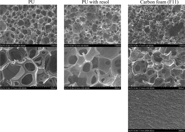
Density measurements, obtained in a gas pycnometer gave a density value of 1.07 ± 0.05 g/cm3 for the carbon foams (F11) which, as expected, was higher than the value for the polyurethane matrix (PU) template (0.88 ± 0.05 g/cm3). This was due to the carbonaceous material that formed after resol impregnation and heat treatment. Images obtained with scanning electron microscope at low magnification (Fig. 3, top line) show that the overall foam morphology is maintained during the process of carbon foam preparation. The PU template impregnated with resol (middle column) maintains the same cell size as the initial PU template (left column). In contrast, the carbon foam (F11, right column) shows shrinkage in the cell dimensions (about 60%), comparing with the initial PU foam. This dimensional shrinkage was also macroscopically observed in the size of the samples upon carbonization. At intermediate magnifications (middle column) it can be observed that some membranes in the cell walls between the cell struts are maintained after impregnation with resol and carbonization. Nevertheless, it is noted that the membranes become less stretched and less smooth after impregnation with resol (middle column), most probably due to some tension induced by the drying of the resol film in the surface of the PU membrane. In fact, at higher magnification (×5 k, not shown) no aggregates on the surface of the materials were noted, indicating that a homogeneous film of resol is formed in the surface of the foam and that this film is preserved after carbonization. These observations are in agreement with the literature [9]. At the highest magnification (Fig. 3, bottom line), the roughness of the surface can be observed, with pores between 4 and 20 nm on the carbon-foam surface. For the other samples, no information could be obtained at this magnification, due to the gold deposit present on the surface.
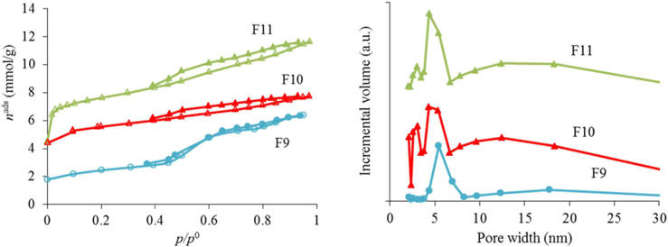
The nitrogen adsorption-desorption isotherms for the carbon foams F9 to F11, and the respective pore size distributions, are given in Fig. 4. Interestingly, and in a way rather different from what happened in the case of the powder materials prepared under the same conditions, carbon foam F9 (the sample only heated at 350℃), already shows mesoporosity. This appears related to the step in the isotherm for relative pressures near 0.5. Nitrogen adsorption-desorption isotherms with a step in this range of relative pressures, but with incipient hysteresis or even with no hysteresis, have already been reported in the literature. These were classified as Type IVc [14] and related to materials with narrow pore size distributions. We ascribe this difference in porosity, compared to the powder materials prepared under the same conditions, to the effect of the PU matrix. Nevertheless, as indicated in Table 1, the specific surface area and the total (micro+meso) pore volume (of F9) is the least of the F9-F11 series. In fact, carbon materials with several types of pore volumes and sizes can be found in the literature when Pluronic F127 (Sigma) is used, with details depending on the precise experimental method used [2,10]. In our case, and most probably because the presence of the polyurethane foam also influences the carbon preparation, the surface area and pore volume values are not amongst the highest values found in the literature, but they are still relevant values. Moreover, the polyurethane foam template is also carbonized during the heat treatment, but does not produce a highly porous carbon. It does contribute to the mass of the final samples, lowering the specific (per mass) surface areas and pore volumes attained. The sample F11 presented the highest specific surface area and pore volumes, and still shows relatively narrow pore size distribution, with the most intense peak centered at 4.3 nm.
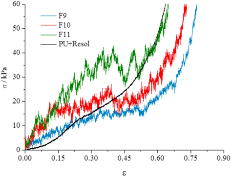
The mechanical properties of the carbon foams were tested to assess the influence of the thermal treatment conditions on the properties of the final carbon foams. The results of compression tests of the carbon foams (Fig. 5) show three segments. Initially, to deformations of about 0.3 ε, the compressive rise in stress indicates that the structure is presenting resistance to the displacement, and that the collapse of the foam structure is starting. From 0.3 to about 0.6 ε almost no increase in tension is needed to increase the deformation of the carbon samples. This section corresponds to a packing of the carbon pieces formed from the rupture of the foam structure. For 0.6 ε to higher values, the tension rises exponentially and corresponds to the deformation of the carbon pieces. Results for higher tensions are shown in the Supporting Information(Fig. S2) The comparison of the curves obtained from the samples heated at 350℃ and 900℃ indicate that the increase in the temperature leads to stiffer materials. Results obtained from the sample subjected to two thermal treatments, first at 350℃ and then at 900℃ (F11), indicate that the two-step preparation significantly increases the rigidity of the material. The results obtained for the foam impregnated with resol (only dried at 100℃) reveal that this material has lower compressive stress at low deformations (<0.15 ε) than F9 and F10, but presents similar results to sample F11 at high deformations (>0.5 ε). However, comparing with PU foams of similar compositions, the sample impregnated with resol shows higher compressive stress at comparable deformations [15] indicating that impregnation with resol increases the stiffness of the foam. The mechanical strength of the carbon foams obtained in this work are lower than those obtained from bulk resol monoliths [16], but this is expected because the carbon foams presented here have macropores several orders of magnitude greater than carbon monoliths prepared from bulk resol monoliths. Also, carbon xerogel and aerogel pellets obtained from resol displayed a much higher compressive strength, although no macroporosity was present in those cases [17].
3.3. Electrochemical properties
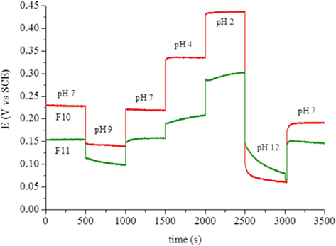
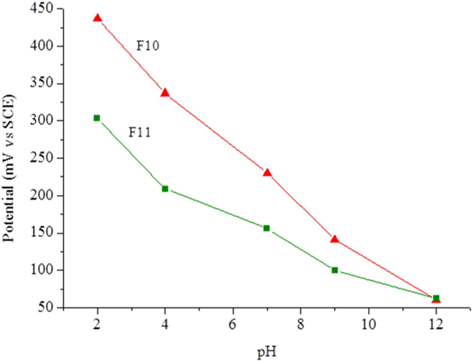
The carbon foam F9 was non-conductive while foams F10 and F11 presented electrical conductivities of 0.0087 and 0.022 S cm−1, respectively. This fact, and their high surface area, led to tests of the electrochemical response of these materials as possible electrode candidates. Cyclic voltammetry was performed with a well-known reversible system (ferro-ferricyanide). The voltammograms showed only an ohmic response, indicating the unsuitability of the present materials for electrolysis. Calcination at higher temperature or for longer times might increase the conductivity of these materials. Another experiment involved the potentiometric response to pH, because virtually no current is needed for this type of measurement. The foams were immersed in standard pH buffer solutions and the potential measured against the SCE. Between solutions, the foams were washed with deionized water. Fig. 6 clearly shows that the foam potentials are strongly dependent on the pH of the solution in which they are immersed. The dependence reveals an almost linear relation (Fig. 7) with sub-Nernstian slopes (−38 to −41 mV/pH unit for F10 and −23 mV/pH unit for F11). The values of pHpzc, measured as described in the experimental section, were similar for both foams and only slightly basic (pH 7.9 and 7.3 for F10 and F11, respectively). The fact that these values are not far from neutral also support the linear response obtained in Fig. 7 and are in line with the absence of acidic type species, like carboxylic or carboxylate types, at the materials surface. This was confirmed by FTIR (Supporting Information, Fig. S3).
In this work, we developed monolithic carbon materials with hierarchical porosity. Two of the prepared materials (F10 and F11) showed an almost linear dependence between the potential and the pH. These materials have high specific surface areas (380 and 582 m2 g–1, respectively) which make them good candidates for supports in sensors.