At the turn of the second century of space exploration, various countries have planned or launched lunar exploration missions, including Korea, which has planned lunar exploration missions for 2018 and 2020. USA also plans to send humans to the Moon (NASASpaceFlight 2006). Besides mission objectives, additional important issues pertaining to manned lunar exploration should be considered. One of these important issues is ensuring a habitat for humans and storage of electronic equipment for survival and protection from potential hazards in the lunar environment.
Unlike the Earth, the Moon has virtually no atmosphere; thus, a variety of highly energetic particles can reach the lunar surface. These energetic particles comprise galactic cosmic rays, originating from outside of the Solar System, and solar radiation and energetic particles, emitted by the Sun. In addition, micrometeoroids and meteorites that can potentially hit the lunar surface, airborne dust particles on the lunar surface, and a wide diurnal range owing to the long rotation period compared to that of the Earth, are primary difficulties encountered during lunar exploration missions.
Galactic cosmic rays, solar energetic particles and radiation result in radiation hazards to humans, and may cause direct and indirect damage to future human residents on the lunar surface. Micrometeoroids and meteorites can hit the lunar surface, making humans on the lunar surface vulnerable to these events. Moreover, streaming charged dust particles on the lunar surface may cause malfunction of expensive and high-accuracy equipment.
Lunar caves are one of the easiest and convenient solutions for protecting humans on the lunar surface from these potential hazards. The existence of lunar caves has been predicted based on the traces of lava activity in the past (Oberbeck et al. 1969; Greeley 1971a, 1971b; Oberbeck 1971; Cruikshank & Wood 1972; Head 1976), and the prospects of using lunar caves as lunar bases have been discussed (Horz 1985; Coombs & Hawke 1992). Most of the highly energetic particles that reach the lunar surface, such as the particles associated with cosmic rays and solar energetic particles, can be shielded from at a depth of 6 m or more below the lunar surface (De Angelis et al. 2002). A cave is a sealed space except for the entrance; thus, caves are free from concerns of big diurnal difference and dust particles. Furthermore, in caves, the lunar surface crust serves as a shield against impacts of micrometeoroids and meteorites; thus, caves could provide a safe haven.
Thus, lunar caves can be potentially used as shelter outposts with natural topography. Because the primary exploration method of lunar caves is satellite-based remote exploration, only vertical-shape caves can be detected. Lunar caves are expected to take the shape of lava tubes. Lava tubes form as a result of the discharge of hot subsurface lava, creating a void under the cooleddown surface lava that was once active and hot. Subsequent physical impacts occurring on the lunar surface, such as meteorite hits or lunar quakes, could lead to the collapse of cave ceilings, forming entrances from the outside and giving the caves their familiar vertical shapes.
Recently, several topographical objects, presumed to be cave entrances, have been discovered at various locations on the Moon (Haruyama et al. 2009, 2010, 2011); overall, ~200 have been identified to date (Robinson et al. 2012; Wagner et al. 2014). It is necessary to investigate these topographical objects for determining how large their inner voids are. Because these topographical objects typically take the shape of vertical pits, they have been called pit craters. Topographical objects, presumed to be cave entrances, have been discovered (Cushing et al. 2007; Cushing 2012) on Mars and are similar to those on the Moon. These topographical objects are widely distributed around the Tharsis Montes. In addition, several groups have identified potential cave candidates on the Moon and Mars surfaces (Hong et al. 2014; Jung et al. 2014).
While pit craters of different sizes have been observed, only a few pit craters have diameters larger than 50 m. Only such large-scale pit craters are easier to analyze owing to the detailed topography of the heap of collapsed ceiling material on the pit floor by using optical images of current spatial resolution acquired by satellites. In this study, two topographical models were devised for examining the relationship between the pit floor terrain and the inner void of pit craters by analyzing the brightness profiles of optical images of the floor terrain of large-scale pit craters. Finally, we analyzed the model brightness profiles that were generated under conditions similar to those under which optical photograph images of the Moon and Mars surfaces were obtained.
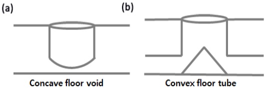
For this experiment, we have created two pit crater models by using paper clay. Pit craters form when a void space exists under the surface and weak surface ground collapses to reveal the void. A concave floor void model has a concave floor with no additional inner void, which is formed when an empty space that remains after the eruption of lava on the Moon and Mars is disclosed after the collapse of weak ground (Fig. 1a). A convex floor tube model has a convex floor and inner void space, which is formed after weak surface ground falls down at the location of a lava tube resulting from volcanic activity (Fig. 1b). In addition to these two topographical models, we used Light Emitting Diode (LED) lights, a camera (Nikon D4), and a tripod, and the experiment was performed in a dark room for reducing the effect of ambient light.
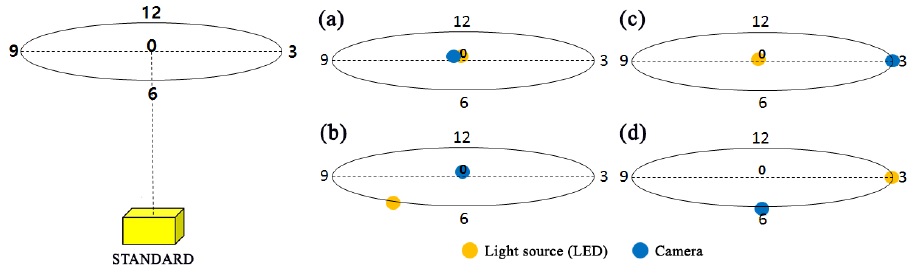
In our experiment, we considered four different arrangements of the models, the camera, and the light. The locations of the camera and light above the model were adjusted in different ways (Fig. 2). The upright position over the model was set to 0, and along the imaginary coplanar circle around the Position 0, the 12 o’clock position was set to represent each location. The arrangements were as follows: 1) both the light source and the camera are located at Position 0 (Fig. 2a); 2) the light source is at Position 7 while the camera is at Position 0 (Fig. 2b); 3) the light source is at Position 0 and the camera is at Position 3 (Fig. 2c); 4) the light source is at Position 3 and the camera is at Position 6 (Fig. 2d).
The shadow of the model crater entrance changes its shape according to the locations of the light source and the camera. Based on this, the brightness profiles were analyzed for changes.
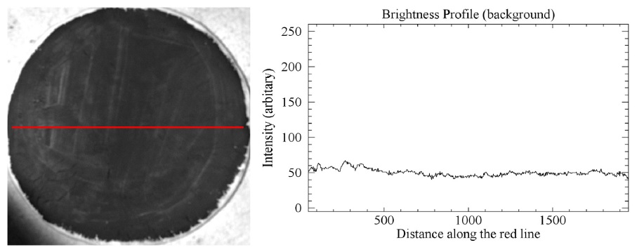
Before analyzing the experimental results, we have inspected the background image of the paper clay to test the evenness of the brightness on the whole area of the flat model due to close position of the light source because if the relative brightness difference between at the central region and at the boundary is detected, the difference should be corrected or the errors should be compensated for. As shown in Fig. 3, fair evenness was confirmed; thus, the experiment was performed as planned.
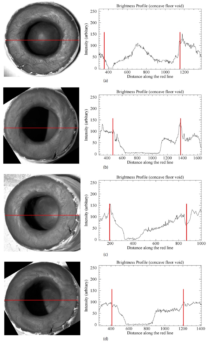
For the concave floor void model, brightness profiles reveal a convex shape around the center of the pit crater entrance (Fig. 4a). In Fig. 4b, the light source location is the same as in Fig. 2b, and the intensity decreases linearly beyond the shadow region. However, in Figs. 4c and 4d, the light intensity is the strongest at the right edge of the pit crater, owing to the direction of the incident light. Thus, in Fig. 2c, the brightness profile gradually increases beyond the shadow region. In Fig. 2d, as the light passes the wall instead of the center region of the concave floor, the brightness profile exhibits a linear behavior. The noise in the brightness profiles in Figs. 4c and 4d results from internal reflection on vertical walls.
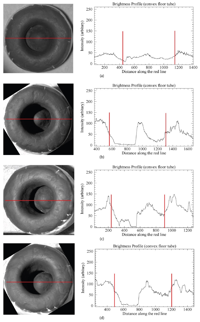
For the convex floor tube model, Fig. 5a reveals an almost constant brightness profile while the central region exhibits higher intensity. Compared with Fig. 4c, the brightness profile in Fig. 5c clearly indicates that there is a convex region in the center. In Figs. 5b and 5d, the brightness profiles are described by bell-shaped curves that decay gradually from the peak of the convex part.
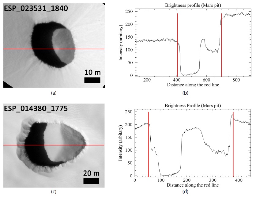
We have compared the model results with those for the topographical objects detected on the Moon and Mars. While the pit craters are larger on the Moon, the corresponding topography cannot be identified unlike in our model; thus, the brightness profiles of the Moon craters were not clear. Therefore, comparison was performed only for the craters detected on Mars. The optical image data were obtained from the High Resolution Imaging Science Experiment (HiRISE) data of the Mars Reconnaissance Orbiter (MRO) (McEwen et al. 2007). The details pertaining to the pit craters on Mars are listed in Table 1. We found that the brightness profiles of Mars craters are similar to the model profiles in Figs. 5b and 5d, which correspond to the convex floor tube model (Fig. 6).
[Table 1.] Pit craters on Mars (http://www.uahirise.org)
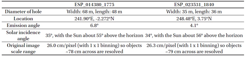
Pit craters on Mars (http://www.uahirise.org)
We have analyzed brightness profiles for identifying void space in pit craters on the Moon and Mars. For this experiment, we have constructed two pit crater models, considering two possible scenarios of pit crater formation: 1) the concave floor void model and 2) the convex floor tube model. These two models were made from paper clay and the positions of light source and camera were adjusted by using a tripod in a dark room, for considering four different scenarios. For each scenario, we analyzed the resultant brightness profiles. In the concave floor void model (Fig. 4), the brightness profile increased linearly with approaching the central region of the model. In the convex floor tube model (Fig. 5), the profile decreased in a parabolic manner with approaching the walls from the peak center. By comparing the models with brightness profiles of real Martian pit craters (Fig. 6), we concluded that the two Martian crater profiles are similar and can be described by bell-shaped curves.
The initial objective of the present study was to identify lava tubes or void space in pit craters by using brightness profiles. However, according to the results of our experiment, while it was not possible to identify lava tubes or void space, we could deduce the existence of inner voids through the identification of floor types of pit craters. The brightness profiles of some pit craters were similar to the brightness profiles of the convex floor tube model, allowing us to better understand the floor shapes of pit craters. Unfortunately, comparison of our models to lunar pit craters was not possible because the brightness profile patterns were not identifiable owing to the incident angle of sunlight. We believe that this issue can be resolved in the future by acquiring a sufficient number of optical images of lunar pit craters. In addition, small-scale lunar pit craters, with diameters less than 50 m, might exhibit a different behavior and allow brightness profile patterns to be obtained. The methods used in the present study allowed us to determine the shape of the material accumulated on the floor of pit craters, which may provide potentially useful information for three-dimensional modeling (Hong et al. 2015). In addition, this knowledge is likely to be of great help in designing explorations of pit craters on the Moon and Mars, and is likely to be useful for searching for potential outposts for human habitat.