Electron microbursts represent the precipitation of electrons during periods of less than ~1 sec at L = 4-8 and 06-18 local times (Parks et al. 1965; Parks 1978). They were discovered by X-ray balloon-borne experiments in the early sixties (Anderson & Milton 1964). Microbursts in the 20-100 keV energy range can be characterized by exponential energy spectra with e-folding energies
Cyclotron resonance between electrons and magnetic chorus waves has been suggested as a possible mechanism for microburst generation (Rosenberg et al. 1990; Skoug et al. 1996; Lakhina et al. 2010; Lee et al. 2014). Here, the term chorus refers to bursty whistler-mode waves with elements of ~0.1-1 sec. The elements comprise coherent sub-elements of ~5-10 msec durations with amplitudes of 0.2-0.3 nT (Tsurutani et al. 2009). The timescales of chorus waves are similar to those of electron microbursts, and the coincident occurrence of microbursts and VLF chorus waves supports the idea that microbursts are produced by resonant interactions between electrons and cyclotron waves (Rosenberg et al. 1981).
Imhof et al. (1992) and Nakamura et al. (2000) reported observations of impulsive electron precipitations with energies exceeding 1 MeV by spacecraft; these precipitations were named relativistic microbursts. However, relativistic microbursts have not been observed by balloon-borne experiments, and at this time it is unknown whether these microburst phenomena are related or originate from the same source.
Quasi-linear theory has been widely used to study pitch angle scattering by wave-particle interactions. In quasilinear theory, the diffusion equation is solved by assuming stochastic particle scattering caused by a succession of small-amplitude and random-phase waves (Lyons 1974; Summers 2005; Albert 2005; Glauert & Horne 2005). Quasi-linear theory provides a good description of the average properties of the diffusion processes, but omits particle trapping and highly nonlinear effects (Horne et al. 2003). Test particle simulation methods, in which the trajectories and pitch angles are calculated stepwise for each particle, include these non-linear effects, but the required calculation time to simulate a complete particle distribution is impractically large (Chang & Inan 1985; Inan 1987; Rosenberg et al. 1990).
Bortnik & Thorne (2007) simulated electron microbursts generated by whistler-mode chorus wave interactions. They calculated the time-averaged pitch-angle changes of resonant particles from an equation proposed by Bell (1984) and estimated the precipitating electron flux by a convolution method. The simulation showed a short-timescale (~0.6 sec) electron precipitation with a peak energy of ~100–300 keV. Hikishima et al. (2010) used a self-consistent full-particle simulation to show that microburst-like precipitations of electrons with energies of 10–100 keV could accompany the generation of discrete chorus-wave emissions. These studies successfully reproduced microburst-like structures by resonant interactions between electrons and chorus waves, supporting the proposed generation mechanism of resonant interactions for microbursts. However, these studies did not address the detailed physical nature of the operations of the interactions in the production of microbursts.
In this study, we used a test particle simulation to investigate the details of resonant wave-particle interactions for electrons in the energy range of ~170–360 keV, including the differences between the fluxes in the parallel and perpendicular directions. We then compared the test particle simulation results with observations made by the Korean STSAT-1 (Science and Technology SATellite), showing that the test particle simulation could reproduce several observed features. These results further support the idea that wave-particle interactions involving cyclotron resonance can generate fast pitch-angle diffusion and thus produce microburst-like precipitations.
Two Solid-State Telescopes (SSTs) on STSAT-1 were launched into a sun-synchronous low-altitude (680 km) orbit on September 27, 2003. The first and second SSTs were aimed perpendicular and upward or parallel, respectively to the direction of the Earth’s magnetic field. The SSTs consisted of 300-μm-thick Si detectors designed to measure electrons in the energy spectra of ~190–360 keV (perpendicular) and ~170–330 keV (parallel). Each SST had a 33.9° Field of View (FOV) with a geometric factor of 0.045cm2 sr. To block ionic and UV radiation from the sun, an Al-coated Lexan foil was placed in front of each detector. Each detector had 30 energy channels with time resolutions of 50 msec, sufficient to resolve microburst structures(Lee et al. 2005; Lee et al. 2012).
STSAT-1 operated successfully over approximately 300 passes through the auroral zone until March 31, 2005. During this period, electron microbursts were detected on six different occasions. An important feature of these observations was the absence of any time delay between the appearance of trapped (perpendicular) and precipitated (parallel) microbursts, which indicated that microbursts were generated by prompt loss-cone filling within a timescale of ~50 msec (the time resolution of the SSTs) or less. If we define the diffusion coefficient (
3. WAVE AND PARTICLE INTERACTIONS
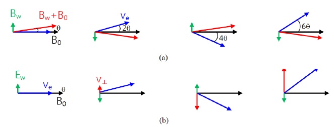
Electron microbursts have been suggested to generate from cyclotron resonance with chorus waves (Rosenberg et al. 1981). Whistler-mode chorus waves possess circularly polarized magnetic components and elliptically polarized electric components (Verkhoglyadova et al. 2009; Verkhoglyadova et al. 2010). For simplicity, we will assume that both electric and magnetic wave components are circularly polarized. Fig. 1 depicts schematically the interactions of whistler-mode waves with electrons. Both electric (Ew) and magnetic (Bw) wave fields can scatter the pitch angles of electrons. However, the specific ways in which they interact with electrons differ significantly.
Let us first consider a magnetic-component wave interaction, shown in Fig. 1(a). Bw is the magnetic field of the wave, B0 is a static background magnetic field, and Ve indicates the electron velocity vector. At the initial state, assuming the electron moves parallel to the background magnetic field where the pitch angle with respect to the background magnetic field is zero, however the actual pitch-angle of the electron is
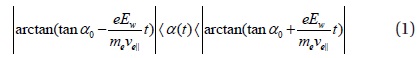
Meanwhile, the electric wave component Ew shown in Fig. 1(b) can accelerate or decelerate electrons. The perpendicular velocity increases or decreases continuously, changing the pitch angle as the resonance condition is satisfied. The electron pitch angle at time

4. WAVE-PARTICLE INTERACTIONS IN A UNIFORM MAGNETIC FIELD
We now show the results and discuss electron pitch-angle variations as calculated by the test particle simulation in a uniform background magnetic field. The assumption of a uniform magnetic field of course does not reflect the real situation. However, this simple first-step approach provides an idea of the timescales of pitch-angle scattering. In Section 6, we extend this simulation model to the dipole field for a more realistic microburst generation.

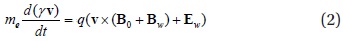
We solve numerically the equation of motion expressed in Eq. (2),where
where
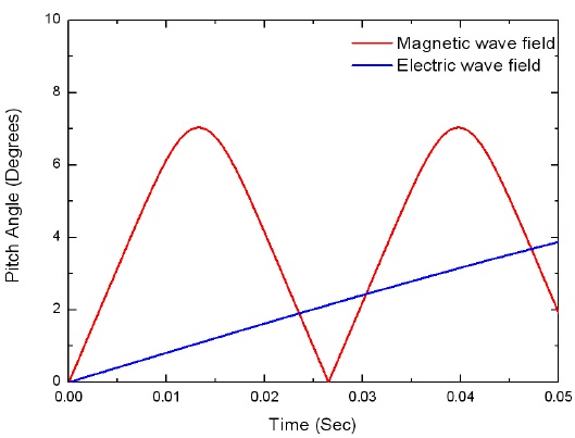
Fig. 2 shows the simulation results of electrons interacting with whistler-mode magnetic and electric wave fields. The red line corresponds to the pitch-angle variation when only magnetic waves of 0.1 nT amplitude are applied to the 300 keV electrons having initial pitch angles of 0°. As time increases, the pitch angle oscillates between a maximum of 7.5° and minimum of 0°. In Fig. 1(a), the electron total velocity was unchanged during the wave interaction, because the process was adiabatic. If the pitch angle were increased, then the decrease in parallel velocity would break the resonance condition of Eq. (3). Therefore, the pitch angles are confined to a limited range, within which they oscillate as shown by the red line in Fig. 2.
When 3 mV/m electric waves are applied, the pitch angle increases linearly, as shown by the blue line in Fig. 2. In the schematic example of electric wave field interaction shown in Fig. 1(b), the parallel velocity component is unchanged and the resonance condition is satisfied during the interaction. In this case, only the perpendicular velocity component is changed, and the pitch angle increases linearly in the non-relativistic case. In a relativistic situation, the increase of velocity changes the relativistic factor
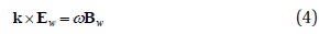
Between magnetic and electric wave fields, one may ask which wave component contributes more dominantly to generate microbursts. This depends on the amplitudes and interaction times of the waves. In the cold-plasma model, the electric and magnetic waves are related by Eq. (4):

where
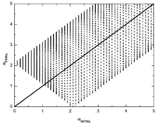
Fig. 2 shows the results of pitch-angle variation for electrons with initial pitch angles of 0°. If the initial pitch angle is not 0°, the motion of the electron depends on the gyro-phase. Fig. 3 shows the results of a test particle simulation in which
5.WAVE-PARTICLE INTERACTION IN DIPOLE MAGNETIC FIELD
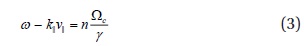
Before we show the test particle simulation results in a dipole magnetic field, we discuss first how the resonance condition is satisfied in a dipole field. In Eq. (3), the gyrofrequency Ω

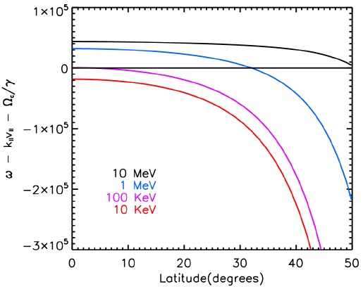
Fig. 4 shows a plot of as a function of the magnetic latitude when 1 kHz whistler-mode waves are applied to electrons with energies of 10 keV, 100 keV, 1 Mev, and 10 MeV. Here, we assume a plasma density of 2 cm – 3 at the equatorial region, L of 5.5, and anti-parallel electron movement relative to k. Notably, when the resonance condition is satisfied, and wave-particle interaction occurs. As shown in Fig. 4, electrons at 10 keV do not satisfy the resonance condition, so their pitch angles are unchanged by wave interactions. However, electrons at 100 keV interact with waves in the equatorial region where the loss cone has a small angle, and electrons can be scattered into the loss cone. This may explain why microbursts are not detected at 10 keV, while 100 keV electron microbursts have been observed (Datta et al. 1997; Lee et al. 2005).
Electrons with energies in the MeV range can interact with waves at high latitudes, where the loss cone angle is larger. In this case, the electrons would have longer angular paths to reach the point at which the pitch angle is zero. Therefore, it is difficult for high-energy electrons to be scattered into the loss cone; higher fluxes would be observed for microbursts with larger pitch angles outside the loss cone than that observed for microburst electrons traveling parallel to the magnetic field direction.
6. TEST PARTICLE SIMULATION IN DIPOLE MAGNETIC FIELD
In our test particle simulation, we assume that waves are generated at the equatorial region of L = 5.5 and propagate pole-ward along the direction of the magnetic field. The waves belong to the whistler mode, with rising frequencies similar to those of chorus waves:

where
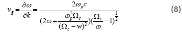
Chorus waves can have amplitudes of 200-300 pT for timescales of~5-10 msec(Tsurutani et al. 2009). We assume constant wave amplitudes of 150 pT for all wave frequencies: the waves move at a group velocity expressed by Eq.(8) derived from the cold plasma model. We assume that the chorus propagates parallel to the magnetic field. It has been shown by ray-tracing methods that off-axis chorus waves will propagate obliquely relative to the magnetic field (Bortnik et al. 2007). We will follow this study with further research to examine more complex cases in detail.
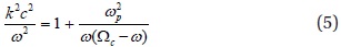
Low plasma density produces a small wave vector k in Eq. (5), and provides an environment in which high-energy electrons can interact with waves at low latitudes. While plasma density data is not available during our microburst events, it is known that the plasma density is ~1 cm-3 at L = 6 (Carpenter & Anderson 1992). We assume a plasma density of 2 cm-3 at the equator; the density depends linearly on the magnetic field. The electric wave field is derived from Eq. (4).
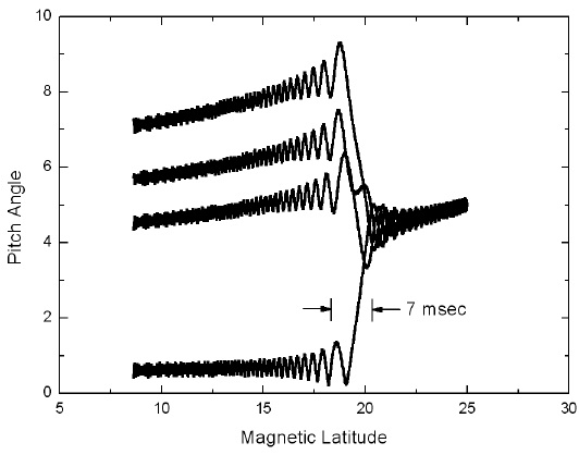
Fig. 5 shows an example of electron pitch-angle changes due to wave-particle interactions in a dipole field. When the wave packet described by Eq. 7 arrives at the magnetic latitude of 25° from the equator, electrons begin interacting with the wave front at 800 Hz. We assume the electrons have initial pitch angles of 5°. At the beginning of the interaction (~25°), the electron pitch angles oscillate at small amplitude because the resonance condition is not fully satisfied. When the electrons move to the lower magnetic latitude of 21°, the wave frequency is increased slightly, thus satisfying the resonance condition. In this region, the pitch angles change dramatically over time scales of 7 msec; the amount of pitch angle variation depends on the gyro-phases of the electrons. Fig. 5 shows the trajectories of four electrons having different gyro-phases.
When the electrons reach the magnetic latitude of 18°, the resonance condition is not satisfied; the pitch angles show small-amplitude oscillations. After the electrons pass through the latitude of 6°, where the waves are terminated at the frequency of 1,200 Hz, they move adiabatically along the magnetic field. Some electrons of various pitch angles and phases can become aligned with the background magnetic field and precipitate into the Earth’s atmosphere. We suggest this mechanism for electron microburst generation.
In order to reproduce the observed electron microburst structures, our simulation used a large number of test particles in a dipole field. As the waves traveled along the magnetic field, we calculated the electron motion for particles of six different energies of 170, 200, 230, 260, 290, and 320 keV. We considered electrons having pitch angles only approaching that of the loss cone, from pitch angles of 3.3° to 10.3° at the magnetic equator. Each electron had a different initial gyro-phase. Each set of test particle electrons began to interact with the waves at different magnetic latitudes, from 5° to 45° at intervals of 1°. The total number of test particles used in this simulation was the six energies × 720 gyro-phases × 280 pitch angles × 40 latitudes. We calculated the motion of each electron with an adaptive step-size control using the Runge-Kutta method. A parallel computing machine having 32 processing cores was used for the calculations.
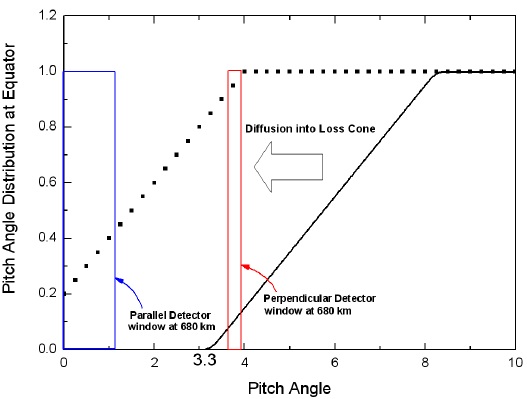
Information on the pitch-angle distribution when microbursts occur is not available, but the distribution could depend on the location and magnetic activity (West et al. 1973). We assumed the electron pitch-angle distribution at the equator as shown by the black solid line in Fig. 6, where the electron loss-cone angle is 3.3° (corresponding to a pitch angle of 90° at an altitude of 100 km). The electron flux increased linearly up to the pitch angle of 8°. Presumably, the equatorial pitch angle corresponding to 90° at the satellite altitude of 680 km is located close to the boundary of the loss cone. When electrons are diffused into the loss cone by wave-particle interactions, as indicated by the dotted line, the electron flux increases would be observed by both the parallel and perpendicular detectors on STSAT-1. We have indicated the parallel and perpendicular detectors as blue and red rectangles, respectively.
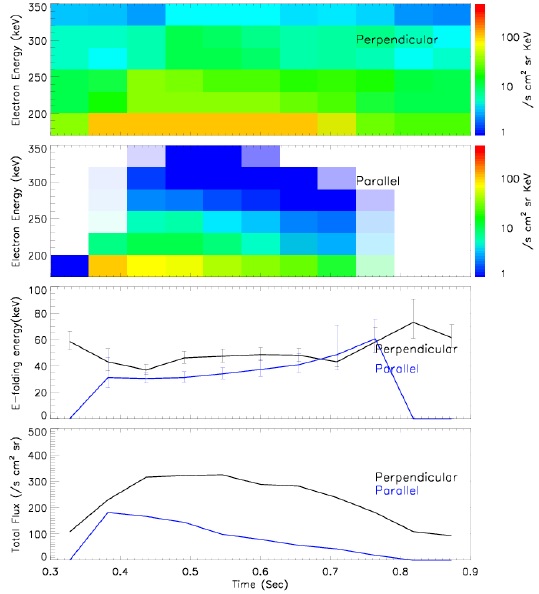
After the electrons interact with the waves, they move adiabatically along the magnetic field, ultimately reaching the STSAT-1 detectors, whose FOV can detect electrons with pitch angles of ~0–17° and ~73–90° for the parallel and perpendicular detectors, respectively, at 680 km altitude. Fig. 7 shows the simulation results. The top two panels show the perpendicular and parallel electron spectrograms, and the subsequent panels show the e-folding energies and total electron fluxes. The simulation results agree well with the STSAT-1 observations. The time shown (at the bottom) is the sum of three time intervals: the time for wave propagation from the equator to the magnetic latitude at which electrons begin interacting with waves (
The test particle simulation can reproduce the microburstlike characteristics observed by STSAT-1. The important findings of our simulation study are the effects of duration and frequency bandwidth of the chorus waves on the microburst precipitation timescale, and the dominance of magnetic wave fields in the pitch-angle scattering, which indicates that the process is quasi-adiabatic.
The simulated electron microburst has a timescale of ~0.5 sec, consistent with those observed by STSAT-1. The main factor determining microburst timescale is the wave occurrence duration (250 msec in this simulation). However, the frequency bandwidth also significantly affects the microburst timescale. If we were to use monochromatic waves instead of multi-spectral waves, the resonance condition would be satisfied only for electrons with a specific energy at specific magnetic latitudes. In this monochromatic case, the electron microburst duration at fixed electron energy would be equal to the duration of the waves. However, if the waves have a frequency bandwidth, mono-energetic electrons can interact with the waves at multiple latitude points. In this case, the microburst duration is increased by the time required for the wave to travel through the interacting region. Thus, the observed electron microburst duration of ~0.25–1 sec appears to result from a combination of wave duration and frequency bandwidth.
Both electric and magnetic wave fields can cause pitch-angle scattering. In our simulation, we found the contribution of electric wave fields for pitch angle changes is ~20%, because the wave-particle interaction time of ~7 msec is very short. This short interaction time results from the non-uniform background magnetic field (a dipole field in our simulation). The dominant contribution of the magnetic wave field suggests that electron microbursts may be generated by quasi-adiabatic processes.
It has been suggested that chorus waves might be crucial to the acceleration of radiation-belt electrons (Boltnik & Thorne 2007; Shprits et al. 2006). While the proposed short wave-particle interaction for generating microbursts does not include significant electron acceleration, it is possible that multi-interactions with chorus waves could accelerate the electrons.
The simulated microburst (Fig. 7) has a fast-rising and slow-falling shape, while the STSAT-1 observations generally show slow-rising and fast-falling microburst structures. Various types and shapes of microbursts have been observed; Datta et al. (1997) showed that the different shapes of these microbursts could correlate to variations of the diffusion coefficient. The diffusion rate depends on the wave amplitude in the wave-particle interaction process, implying that microburst shapes are determined by whistler-mode wave structures. In our simulation, we applied waves of constant amplitude, yet chorus waves have substructures with amplitudes that might be changed during propagation (Tsurutani et al. 2009).
The simulation results indicate that high-energy electrons can interact with waves at high latitudes, where the loss cone is large and the background magnetic field is strong (Fig. 4). In addition, the interaction time is shorter because of the higher parallel speeds. At high latitudes, the strong background magnetic field reduces the magnetic wave field effect, as shown in Fig. 1(a). The electric wave field interaction is independent of the background magnetic field, yet only electrons having large parallel velocities can satisfy the resonance condition at high latitudes. Thus, electric and magnetic wave field interactions are not effective for scattering the pitch angles of electrons at high latitudes.
This may explain why only low-energy (<100 keV) microbursts have been observed by balloon-borne experiments that detect the X-rays produced by low-energy field-aligned electrons. Notably, relativistic-energy microbursts have only been observed thus far in situ on spacecraft-borne detectors. These spacecraft did not utilize altitude-control systems, and the detectors measured both high-energy electrons in the perpendicular direction and lower-energy electrons in the parallel direction. Lee et al. (2005) showed that the e-folding energy of microbursts increased following magnetic storms, allowing in-situ measurements to detect relativistic microbursts. It is thus possible that low-energy (< 100 keV) and relativistic electron microbursts arise from the same source.
Our test particle simulation model is not self-consistent. Moreover, we assumed constant wave amplitudes with a simple cold plasma model. Nevertheless, our model successfully simulated microburst-like precipitation and electron energy spectra similar to those measured by STSAT-1. This model will be improved to describe the detailed temporal and spatial structures of electron microbursts in future studies. However, at the present time, little information is available on the spatial scales of relativistic microbursts. Future measurements of spatial scales with a constellation of small satellites (for example, CubeSats) can provide important information on the exact spatial and temporal scales of relativistic microbursts.