The two-mirror system has significant applications in optical astronomy and the remote sensing field due to its inherent characteristics, such as that oversized mirror material could be obtained more easily than oversized optical glass, silver reflection coating and aluminium reflection coating have high reflectivity in a wide spectral band, mirror system achromatic characteristics and so on. The Cassegrain system and the Gregory system are the representative systems in the early stage of two-mirror system development. Schwarzschild, Chrétien, Ritchey and Cuder successively designed more outstanding two-mirror systems which can correct aberrations well and achieve a wider field of view (FOV). With the rapid development of computer and optical design software, more and more remarkable two-mirror systems have been proposed. The unobstructed system ICOROT telescope [1], designed by Frenchman J. M. Sasian, launched in 2006, adopted a two-mirror system which contained tilt optical elements and battery of lenses to achieve a wide FOV of 2.7° × 3.05°. Jose M. Sasian designed a kind of Schwarzschild flat-field, anastigmatic, unobstructed, wide-field telescope and achieved a FOV of 4.5° × 6° [2]. Dr. Liu with his design team from Research Center for Space Optical Engineering, Harbin Institute of Technology (HIT) designed a flat field unobstructed two-mirror system which can achieve a FOV of 6° × 6° and 20° × 1°, but he didn’t report the design theory and method comprehensively [3]. However, all of these optical systems didn’t achieve both a long focal length and a wide FOV.
We can learn from the history of the optical system development, a significant part of the imaging optical system people desire is still a system which possesses the long focal length, wide FOV and fast F-number. However, the two-mirror system is clearly different from other systems; it has finite optimizing degrees of freedom (DOFs) because of the simple optical configuration. In order to achieve the design goal, more optimizing degrees of freedom (DOFs) have been developed by the optical system designers; the typical case is that of optical freeform surfaces, which is a category of nonrotational symmetric surfaces which have strong abilities in aberrations correction due to their multi-DOFs compared with conventional optical surfaces [4]. In recent years, optical researchers Sun
In this paper, we present a design of an unobstructed off-axis two-mirror system which proposed applying diffractive mirrors to realizing aberration suppression in order to achieve a wide FOV. This design is based on these works: firstly, a suitable two-mirror system initial configuration is established based on third order aberration theory, the authors analyze the initial configuration multi-solution, and make the suitable choice from the point of configuration rationality. Secondly, the authors build a well-understood simplified relationship between diffractive phase coefficients and Zernike aberrations, and the relationship shows the aberration correction ability of the diffractive phase coefficients in a well-understood way. Thirdly, a complete contrast design example is given. Otherwise, in this system, we achieve a symmetrical imaging quality about the tangential plane according to the modulation of diffractive phase coefficients, the symmetry aberration performance will bring convenience to alignment and testing for the system, and it will make the alignment of the two-mirror system easier.
II. ESTABLISHING INITIAL CONFIGURATION BASED ON THIRD ORDER ABERRATION THEORY
The off-axis mirror system is more and more popular with the improvement of the mirror manufacture and alignment technique. With the progress of aberration research it has been realized that an off-axis mirror system has many intrinsic advantages compared with a coaxial mirror system. From the nodal aberration theory, in a two-mirror system, the tilt angle and lateral displacement of the secondary mirror could bring aberration compensation in astigmation and coma [6], and mirror off-axis magnitude has the correction function for distortion correction, and so on. These optimization variables will bring convenience for aberration correction, and the quantity of the optimization DOF has also been increased. Furthermore, no obscuration is a characteristic of the off-axis mirror system which makes a better spot diagram energy concentration [7].
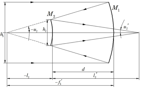
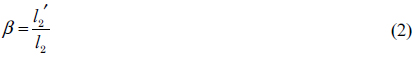
An off-axis two-mirror system (OTS) could derive from a coaxial two-mirror system. Generally, an OTS begins with solving the initial structure of a coaxial two-mirror system, which is shown in Fig. 1. M1 and M2 are the primary mirror (PM), secondary mirror (SM), -f1′ is the focal length of the PM, l2, l2′ are the object distance and image distance of the SM, respectively. h1 and h2 are the diameters of the PM and SM, respectively. u2 and u2′ are the object aperture angle and image aperture angle of the SM, respectively [8].
In the system, there are 2 variables, α, β, which are PM obscuration ratio caused by SM, SM magnification, respectively; they can express all of the concerned parameters, including the original profile and 3rd-order aberration coefficients.

The normalized profile parameters (normalized with respect to the system focal length) of initial structure can be expressed based on paraxial optical theory: r1, r2, d are the PM radiuses of curvature, SM radius of curvature, thickness between PM and SM, respectively.

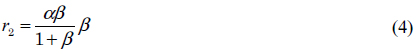

Following Eqs. (3)~(5), r1, r2, d are directly expressed by α, β which means, from a set of α, β, these structure parameters can be determined uniquely.
In the two-mirror system, we set the PM as the stop, then there are relationships between 3rd-order aberration coefficients, that is, Seidel spherical aberration coefficient SI, Seidel coma aberration coefficient SII, Seidel astigmatism aberration coefficient SIII, Seidel field curvature aberration coefficient SIV, Seidel distortion aberration coefficient SV and the design variables α, β:
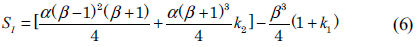
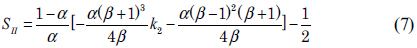
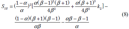
The relationships between aberration coefficients and α, β can be expressed by a set of equations:

Where k1and k2 denote the conic constant of PM and SM. Ai, Bi (i=1, 2…5) are functions of α and β.
Following Eqs. (6)~(11) we can know, there are 4 variables α, β, k1 and k2 in the two-mirror system aberration expression, so the system could correct 4 types of aberrations at most. In theory, we could set up five equations from the aberration matrix Eq. (11), to make four types of aberrations zero to get the initial construction of the two-mirror system. The five equations are:


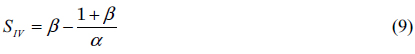
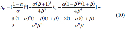
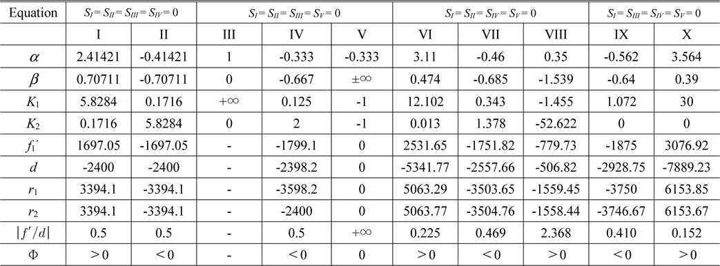
What should be mentioned is that, because the PM has been set as the stop, also the entrance pupil, if SI≠0, k1 will become invalid due to its malfunction on correction of the off-axis aberrations [9], so there is no solution of Eq. (16). We can get a set of solutions of Eqs. (12)~(15). Combining with Eqs. (3)~(5), a set of initial configurations of a two-mirror system with a focal length of 1200 mm and F-number of 12 is shown in Table 1.
[TABLE 1.] Initial configurations of a two-mirror system
Initial configurations of a two-mirror system
From the Eqs. (12)~(15), we get 10 sets of solutions which are marked in Roman numerals from I~X. From the Table 1 we can see, the systems’ power of the groups II, IV, VII, IX are negative, and they are divergent optical systems which cannot be applied in an imaging system. The system power of the group V solution is zero, and it is an afocal system which cannot achieve an imaging function. The SM magnification β of the group III is zero, the corresponding radius of curvature of SM r2 is zero, and this kind of system is non-existent. The size of optical construction is a significant index of an optical system, however, thickness between PM and SM of the group VI and X solutions is too large to satisfy, the ratio between focal length and thickness between PM and SM are just 0.225 and 0.152. In the group VIII, the conic of SM is -52.622, the asphericity is too large to manufacture. In summary, the parameter of group I is suitable for establishing a two-mirror system. In the next work, the initial configuration of a two-mirror system will be established based on the group I parameters. Besides, for the sake of establishing an unobstructed off-axis system, the mirror off-axis magnitude will be applied on this initial configuration. Before designing the system, we will prove the aberration correction function of the DOEs in theory and then achieve our design target.
III. DIFFRACTIVE MIRROR FOR ABERRATION CORRECTION
DOEs have strong ability in aberrations correction that benefit from their phase modulation function. D. A. Buralli and G. M. Morris have developed the formula for the five paraxial aberrations for the stop in and not in contact with the diffractive elements. They have also given the example that the Seidel aberration theory can be used in lens design with Sweatt and Kleinhans models which have shown that DOEs and thin lenses have similar Seidel aberration characteristics [10].
Based on these theories, DOEs have been used in Seidel aberrations correction in the past few decades. In recent years, with the development of the aberration theory, Zernike aberration has been widely used to describe an optical system. Furthermore, more and more optical investigators have paid attention to express the relationship between Zernike aberration and DOEs’ parameter. The binary optical element is a kind of significant element of DOEs, and it has been used in diffractive optical systems extensively for many years. In this paper we will use an easily-understood way to derive the relationship between Zernike aberrations and binary optical element parameters. The phase difference modulated by the binary element can be expressed as:
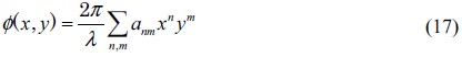
Where
Accordingly, the OPD difference modulated by the binary element in the polar coordinates is:
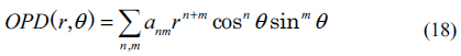
Zernike firstly proposed the concept of Zernike polynomials in 1934 [11], and in the following decades Zernike polynomials have been extensively used in describing the diffraction theory of aberrations. Zernike polynomials are the function of r, sin θ and cos θ, where r is the semidiameter of the pupil, and θ is the azimuthal angle. The corresponding relationship between Zernike polynomials and aberration types are independent of Zernike polynomials’ sequence. In this paper, we adopt a kind of imprecise easily-understood mathematical expression expressed as Eq. (19) to describe the Zernike polynomials in order to establish a common mathematical form between Eq. (18) and Eq. (19).
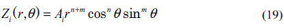
Where Ai is the Zernike coefficient. Combining Eq. (18) and Eq. (19), we could get the relationships between Zernike coefficients and DOEs’ diffractive phase coefficients which listed in Table 2. It can be concluded that the DOEs also have the ability to correct the Zernike aberrations, and DOEs’ diffractive phase coefficients have the corresponding relationships with Zernike aberrations.
[TABLE 2.] The relationships between Zernike coefficients and diffractive phase coefficients
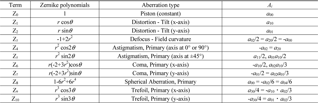
The relationships between Zernike coefficients and diffractive phase coefficients
Unfortunately, in the past few decades little attention has been paid to how to use a diffractive mirror to correct Zernike aberrations in a mirror system. Diffractive elements can be made as reflective devices as well as transmissive. The diffractive pattern can be etched into metal directly, or a very thin reflective coating can be applied to a diffractive structure [12], and both varieties have been successfully manufactured. In the next section, we will design an unobstructed off-axis two-mirror system based on the initial configuration which we obtained in Section 2; in the system we will verify the aberration correction ability of the diffractive mirror.
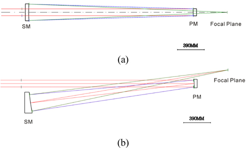
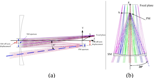
Based on the analysis of the previous sections, an off-axis two-mirror system with PM set as stop is designed based on the initial configuration which we obtained in Section 2. The initial configuration is shown in Fig. 2, and an off-axis magnitude of 200 mm is added on to the initial configuration to establish an unobstructed off-axis system.
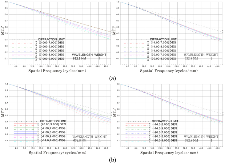
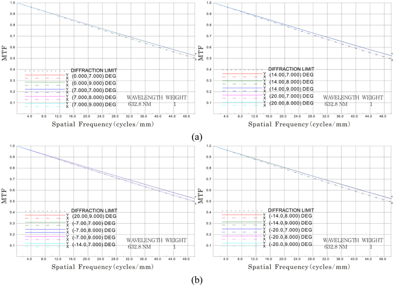
The system with a focal length of 1200 mm and F-number of 12, and the rectangle FOV of 40° × 2°, the sagittal direction (x direction) FOV is 40° where the range is from -20° to 20°, and tangential direction (y direction) FOV is 2° where the range is from 7° to 9°, off-axis magnitude of PM is 200 mm, the system multidimensional scheme is shown in Fig. 3. The design reference wavelength is 0.6328 μm. The optimization process can be achieved with the optical design software CODE V [13] via establishing merit function, setting the optimizing boundary condition after the initial configuration is given. The modulation transfer function (MTF) is shown in Fig. 4. The system average wavefront error is 0.061 λ (λ=0.6328 μm).
In this system the surface type is asphere, based on the system, in order to verify the aberration correction ability of the diffractive mirror and to achieve more excellent image quality; phase polynomial was added as the mirror diffractive properties. The phase polynomial expression is Eq. (17). What should be mentioned is that the phase polynomial expression is similar with the freeform surface XY polynomial surface, x represents the sagittal direction and y represents the tangential direction of the optical system [4]. In order to obtain the axially symmetric wavefront which could bring convenience to the integration and test for the optical system, only even order terms of x of Eq. (17) are retained in the design. The new phase polynomial expression can be expressed as (only the first 20 items of the equation were adopted):

According to the optimization with the new phase polynomial expression by CODE V, the system final configuration parameters are shown as Table 3. What is striking is that the size of SM which adopted diffractive phase coefficients is 1862 mm × 324 mm, it is really difficult to manufacture such a large-size DOE. Fortunately, we can obtain more and more news of progress of the successful manufacture and application of large-size DOEs. In Southern African Large Telescope (SALT), an echelle grating with the size of 204 mm × 407 mm was applied in the high resolution spectrograph [14]; an echelle grating with a size of 267 mm × 1067 mm, a blaze angle of 76° was applied in Airborne InfraRed Echelle Spectrometer (AIRES) [15]; In addition, University of Rochester developed a large-aperture grating tiling method, and this method was successfully used for tiling a tiled-grating assembly composed of three full-size gratings (470 mm × 430 mm, 500 mm in diagonal) with interferometric precision [16]. Furthermore, LLNL (Lawrence Livermore National Laboratory) has manufactured a large area grating with a size of 910 mm × 420 mm, and PGL (Plymouth Grating Laboratory) also has manufactured a large area grating with a size of 910 mm × 450 mm [17]. To sum up, the large size DOEs have the probability of application in optical systems, and we also should have the patience to pay close attention to the DOEs’ development.
[TABLE 3.] Configuration parameters
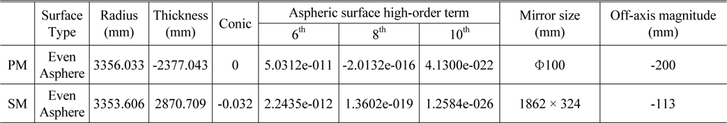
Configuration parameters
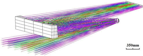
The phase coefficients of the diffractive mirror are shown in Table 4. The 3D viewing schematic is shown in Fig. 5.
[TABLE 4.] Phase coefficients of diffractive mirror
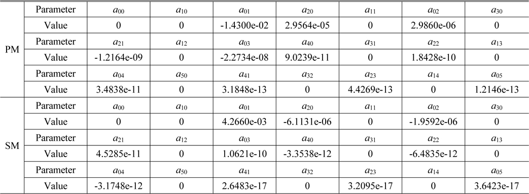
Phase coefficients of diffractive mirror
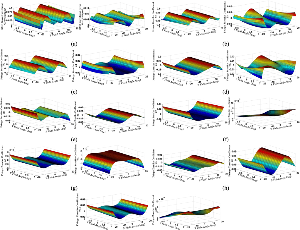
The MTF value of the new system which is shown in Fig. 6 has been significantly improved owing to the application of the diffractive mirror which can increase the DOFs excellently. Compared with the system without the application of the diffractive mirror, the minimum MTF value is 0.35@50 lp/mm shown in Fig. 4, and in Fig. 6 the MTF values are all greater than 0.5@50 lp/mm. The system average wavefront error is 0.007 λ (λ=0.6328 μm) developed from 0.061 λ when the system didn’t adopt the diffractive mirror. We can also see from the field map that almost all kinds of Zernike aberration coefficients values have decreased, which was a benefit from the application of the diffractive mirror shown in Fig. 7. Although the application of the diffractive mirror will introduce chromatic aberration due to the dispersion, theory proves that the diffractive optical elements have a strong ability in chromatic aberration correction [18], and the contrast design shows that the diffractive mirror’s obvious advantage of the aberration correction abilities far outweighs its weakness caused by dispersion. So, the system with the diffractive mirror has a better image quality than the system without a diffractive mirror. Furthermore, because the new phase polynomial which is shown in Eq. (17) is adopted in the diffractive mirror, a symmetrical imaging wavefront about the tangential plane has been achieved shown in Fig. 7(a). The symmetrical imaging quality about the tangential plane can be proven by the spot diagram shown in Table 5, and it can make alignment convenent.
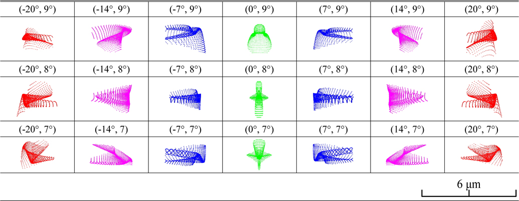
Spot diagram
Regrettably, the system still exhibits residual geometric distortion which is a constant value, it can be calibrated, and it also can be corrected well by the compatible mathematical model and correction algorithm. An all-reflective unobscured zoom optical system designed by Kristof Seidl, Jens Knobbe, Danilo Schneider and Hubert Lakner also exhibits significant distortion [19], and based on the specific mathematical model, the distortion has been corrected well. What is excellent is that a hardware-integrated electronic solution can provide a real-time correction of the zoom system whose difficulty of the distortion correction is larger than for the fixed focus optical system. Based on this theoretical foundation and overt engineering application, we will research the system geometric distortion correction in the next step.
Another point what we should mention is that because of the finite diffractive efficiency of DOEs, a part of energy will be lost which makes the actual F-number of the optical system slower. With the engineering progress, such as high quantum efficiency detector, image processing technology, computer-aided alignment technology and so on, the slow optical system with high F-number has been accepted and applied successfully in many cameras, such as HiRISE [20] (High Resolution Imaging Science Experiment) with F-number of 24, which was launched on 12 August 2005 and has obtained a large number of high quality Mars photographs [21]. Although our system loses a part of energy because of the finite diffractive efficiency, it also can be applied in many fields.
In summary, the current technique level can solve the weakness of this two-mirror optical system, and the system has a certain application value and potential in the optical imaging field, and it also should be verified in the next engineering implementation.
V. ELEMENTARY APPLICATION AND TOLERANCE ANALYSIS
The optical system is in the preliminary design phase, and only some limited analysis has been accomplished. In the reflective diffractive element manufacture process, fused quartz is usually applied as the substrate material, and photoresist or metal thin film is coated on it, then the diffractive layer is obtained by the methods of exposure or precision ruling. In a space application environment, extremely low expansion glass ceramic such as Schott product ZERODUR has better performance in mechanical properties and thermal properties than fused quartz, for example the ZERODUR mean coefficient of linear thermal expansion (CTE) can achieve 0±0.007 × 10⁻⁶/K, which is much lower than fused quartz 0.055 × 10⁻⁶/K. In this system, ZERODUR is applied as the substrate material, and uniform aluminum film is coated on it as ruling layer. Substrate material surface error has an important influence on diffractive layer ruling accuracy, so the substrate material ZERODUR should be polished smoothly before diffractive ruling.
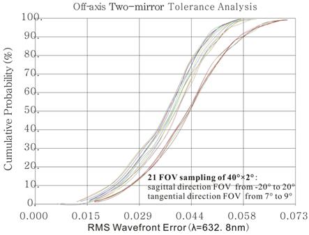
Based on the current research stage, only substrate material manufacture tolerance and system alignment tolerance have been analyzed in a Monte Carlo method. The substrate material manufacture tolerances are random RMS surface error, radius delta, and conic constant delta. During the two-mirror system alignment process, SM is set as reference, and the SM alignment tolerances are surface displacement, surface tilt (both in tangential and sagittal directions) and surface rotation, and the thickness between PM and SM and the back focal length are set as compensators. The tolerance values are shown in Table 6.
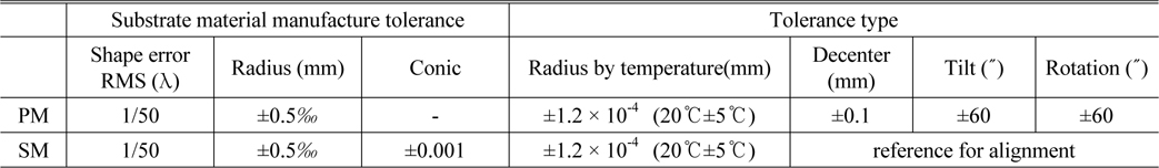
Tolerance value
Based on the tolerance allocation, 500 times Monte Carlo is analyzed, and the cumulative probability of system RMS wavefront error is shown in Fig. 8. The system final wavefront error 97.7% probability reaches to 0.0668 λ (λ/15) based on the tolerance value allocation.
In this paper an unobstructed off-axis two-mirror system is established based on 3rd-order aberration theory. For the sake of obtaining more optimizing DOFs and achieving more perfect image quality and wider FOV of the two-mirror system, a kind of easily-understood simplification mathematical relationship between diffractive phase coefficients and Zernike aberration coefficients is derived to verify the aberration correction abilities of diffractive mirror. Furthermore, a comparison design of the two-mirror system is accomplished, in this two-mirror system which applies diffractive mirrors, a new diffractive phase polynomial which only even order terms of x direction (sagittal direction) are retained is adopted and then a symmetrical imaging wavefront about the tangential plane has been achieved, and this characteristic can bring convenience for testing and alignment. The comparison design shows that the diffractive mirror has a strong ability in aberration correction; almost all kinds of Zernike aberration coefficients values have been decreased by the benefit from the application of the diffractive mirrors. Finally, the two-mirror optical system achieves a focal length of 1200 mm, F-number of 12, and FOV of 40° × 2°, the MTF value approaches the diffractive limit, the system average wavefront error is 0.007 λ (λ=0.6328 μm) developing from 0.061 λ when the system doesn’t adopt a diffractive mirror. Furthermore, based on the current research stage, substrate material manufacture tolerance and system alignment tolerance analysis are carried out, and the final wavefront error is about λ⁄15 while the tolerance values are realizable.