A zoom system consists of several groups including a variator for zooming and a compensator for keeping the image plane stationary. Because the movement of a compensator is generally smaller than that of a variator, a compensator can be replaced by a liquid lens. Zoom systems having one moving group plus a liquid lens have been reported [1, 2], but the liquid lens actuated by electro-wetting is composed of a cell filled with two immiscible liquids. One is an oil-like electrical insulator, and the other is an electrolyte. Because of small refractive index difference between these materials, the magnitude of a changeable optical power obtained by this liquid lens is limited compared to that of a focus tunable lens.
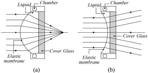
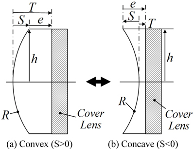
Figure 1 shows the structure of the focus tunable lens (FTL) composed of a liquid and a thin elastic membrane enclosing it [3, 4]. An optical liquid is concealed in a container with at least one side being an elastic membrane. A change of pressure in the container causes the membrane to deflect, thus forming a lens. This tunable lens design has the advantage of being convertible from a convex to a concave shape. Thus, various focal lengths can be obtained by changing the curvature of a thin membrane. Since the focus tunable lens has also the big refractive index difference between the materials of air and liquid, not liquid and liquid, it can make greater changes in optical power than previous liquid lenses even for the same curvature. In addition, the focus tunable lens is known to be much more stable from the gravitational force at large aperture than the liquid lens is [4]. Because of these merits of a focus tunable lens, we can use it as a compensator in a compact zoom lens design.
Much research on optical systems using liquid lenses has been reported. Most of them are for auto-focusing by a liquid lens [5, 6]. However, such lenses can be used to compensate for image position errors generated by changes in the power and the object distance.
Focus tunable lenses performing well as a compensator in zoom systems have also been reported [7, 8]. In 2013, Lee proposed a zoom lens using tunable lenses for a laparoscope, which has the apertures of
In this research, to achieve a higher zoom ratio of 8x, we propose a four-group inner-focus zoom system having one moving group by employing a focus tunable lens. We locate the FTL at the fourth group as a compensator. Because this group is always fixed, so the curvature of an FTL should be changed to compensate for image position errors induced by focal-length changes at different zoom positions. This configuration enables the zoom lens to have a higher zoom ratio of 8x and a compact size.
II. ANALYSIS OF A FOUR-GROUP INNER-FOCUS ZOOM SYSTEM WITH COMPENSATOR OF FOCUS TUNABLE LENS
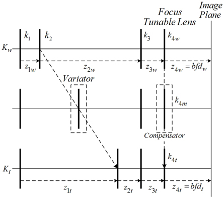
The layout of the four-group inner-focus zoom system, consisting of a focus tunable lens, is shown in Fig. 2. The powers of the groups are denoted by


where
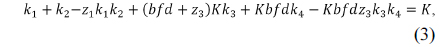
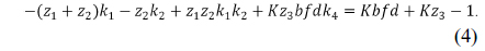
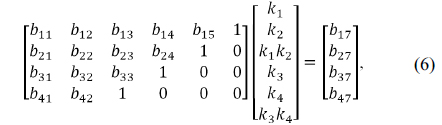
Therefore, Eqs. (3) and (4) can be expressed in a matrix form for wide and tele positions as follows:
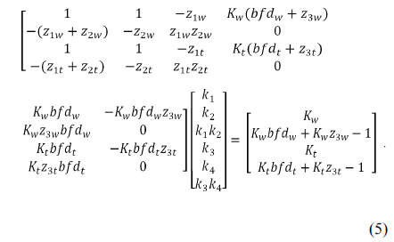
If the Gauss-Jordan elimination method is applied, Eq. (5) is replaced by

where


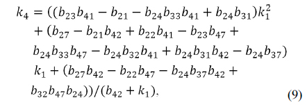

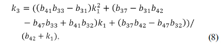
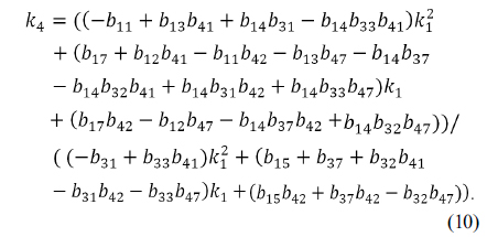
Plugging the condition of Eq. (9) into Eq. (10) results in an expression for the unknown parameter

where coefficients of
III. PARAXIAL DESIGN OF AN 8X FOUR-GROUP INNER-FOCUS ZOOM SYSTEM
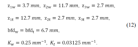
The paraxial design for a zoom system is carried out at two extreme positions. To reduce the amount of the curvature variation at the FTL, the powers of the fourth group including an FTL are set to be the same at wide and tele positions. This configuration can realize a simple and mechanically stable zoom system. For the initial design of an 8x four-group inner-focus zoom system, we input the proper distances between principal points and the targeted total powers at the wide and the tele positions. These starting values are empirically selected to satisfy the following basic requirements for an 8x compact zoom system:

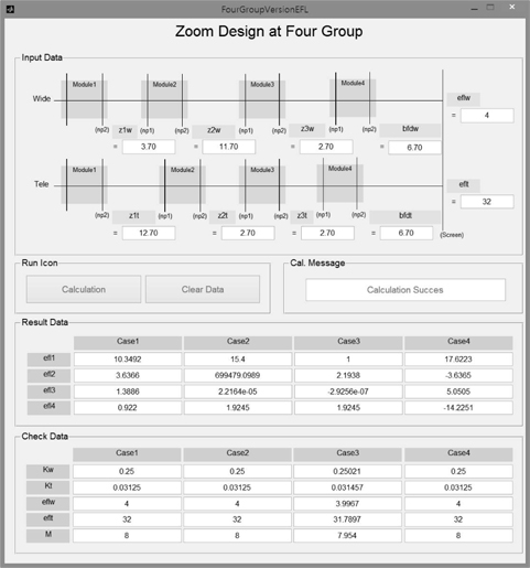
By inputting these starting values for Eq. (12) into the program tool, we can immediately obtain the power of each group, as shown in Fig. 3. In that figure, the Result Data shows the four solution cases obtained from Eq. (7) to Eq. (11). These solutions for
[TABLE 1.] Focal lengths of groups at four solution cases (in mm)
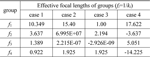
Focal lengths of groups at four solution cases (in mm)
The next step is to select the physically-meaningful data among solutions given in Fig. 3. This process can be carried out by executing the ray trace and the ‘Check Data’ analysis of the program developed in this study. The case 4 of Table 1 is confirmed to fulfill the requirements for the available zoom system with 8x.
IV. INITIAL DESIGN FOR AN 8X FOUR-GROUP ZOOM LENS
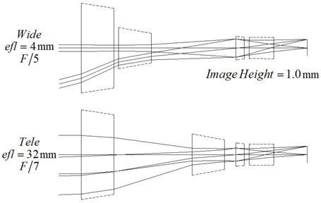
We have set up a zoom lens system with four thick-lens modules, for which the power of each lens group and the zoom loci inputs are taken from the case 4 of Table 1 and Eq. (12), respectively. The lens modules do not reflect higher-order aberrations, so reducing the aperture and the field size of the system is desirable. Thus, we took a zoom system with a half image size of 1 mm and f-numbers of
In order to get an initial zoom system, we optimized the lens module parameters so that the specific constraints were satisfied [12]. In Table 1 of the previous section, the thickness of each group and the air spaces are not presented. They can be derived by specifying the design variables of the lens modules, such as the front focal length (
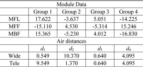
Design data for the lens modules and air distances between modules in the lens module zoom system (in mm)
Numerically analytic approaches using extensive calculations to obtain zoom locus have been reported [1, 10, 11]. However, handling many equations given in Section 2 at the same time is very complicated and requires much more effort. First of all, handling analytically all the first-orders of an FTL at all zoom positions is hard work. In this research, therefore, we analyze the zoom loci at all positions by optimizing the lens modules.
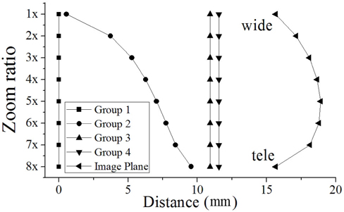
First, we calculate the image position shifts induced by the variator’s moving at different zoom positions, as shown in Fig. 5. We then locate the focus tunable lens at the fourth lens group as a compensator. Because this group is always fixed, so the curvature of an FTL should be changed to compensate simultaneously for image position shifts induced by focal-length changes at different zoom positions.
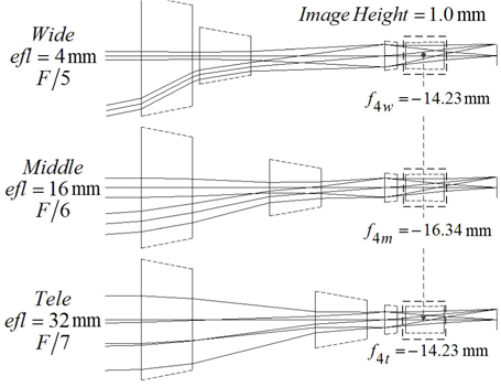
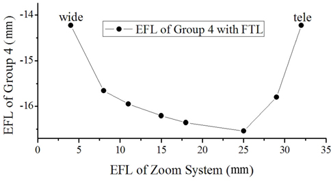
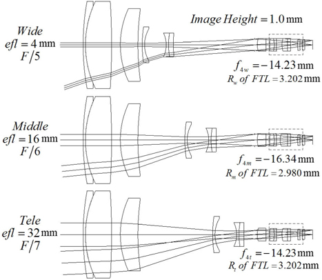
Figure 6 shows the lens module zoom system with a fixed compensator, of which focal lengths are changed from -14.23 mm to -16.34 mm to -14.23 mm. Figure 7 illustrates the focal lengths of the fourth group at various positions.
V. OPTIMIZED DESIGN FOR A ZOOM SYSTEM USING FOCUS TUNABLE LENS
5.1. Converting Lens Modules into Real Lens Groups Successively
In the lens module zoom system of Fig. 6, four lens modules were successively, not separately, converted into real lens groups using an automatic design method. The conversion of the lens module into a real lens group is based on the first-order properties given in Table 2 and Fig. 7.
At first, the first lens module is converted into the real lens equivalent to the module within the first-order properties, while the other three groups are lens modules and, unlike the first group, have not yet been carried through this converting process. By these iterative processes, the second group, third group, and fourth group are successively converted to real lens groups [13]. As a result, the lens module zoom system is group by group converted to the initial real lens zoom system without losing the equivalence to each other.
In the converting process of the fourth lens group, the curvature of a focus tunable lens should be changed to keep the image plane stationary at different zoom positions. From the structure of an FTL in Fig. 1, while the edge thickness (


The focus tunable lens as a compensator is designed to satisfy the conditions for its sag and thickness given in Eqs. (13) and (14), respectively. Its edge thickness was constrained to be more than 0.4 mm so that the curvature of the membrane can be sufficiently changed. Figure 9 represents the initial real lens zoom system combined due to the zooming locus listed in Table 3. As compared Fig. 6 to Fig. 9, the agreement for the first-order properties between both zoom systems is complete. This design procedure results in a real lens zoom system equivalent to the lens module zoom system. Table 3 shows the first-order quantities and zooming loci of an initial real lens zoom system.
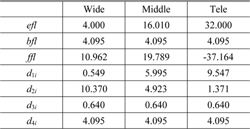
First-order properties and zooming loci of an initial real zoom system with an FTL (in mm)
5.2. Optimized Design for Zoom System with an FTL
In the initial design of Fig. 9, to meet the current specifications for a zoom camera, the aperture and the field size should be increased. The f-numbers are extended to
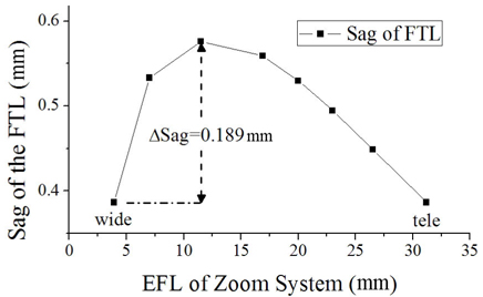
Figure 10 illustrates the sag of the finally designed FTL at various positions, and Table 4 lists its design data. To reduce the magnitude of the sag’s variation at the FTL in this study, the focal lengths of an FTL are set to be the same at wide and tele positions. The variation of the sag from a wide to narrow field is less than 0.189 mm. It is such a small value that this configuration can realize a simple and mechanically stable zoom system.
[TABLE 4.] Design data for the FTL in an aberration-balanced zoom system (in mm)
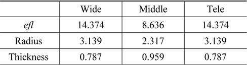
Design data for the FTL in an aberration-balanced zoom system (in mm)
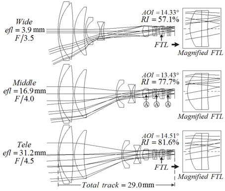
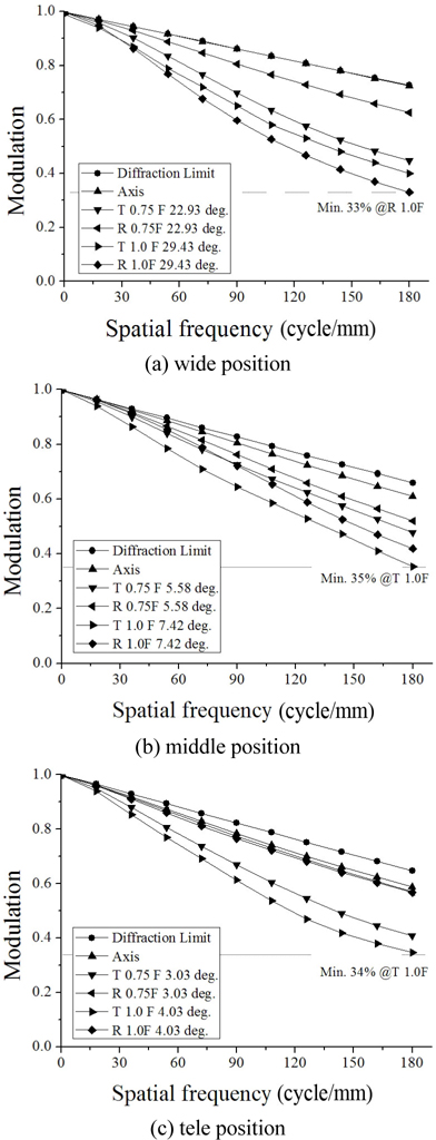
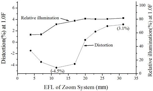
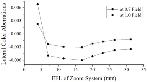
The layout of the finally designed zoom system is shown in Fig. 11. This system consists of 11 elements including an FTL and three aspherical lenses. The maximum diameter of the front group is 17.4 mm. Aberrations are significantly reduced. From Fig. 12, the modulation transfer function (MTF) at 180 lp/mm is more than 33% over all fields at three positions. The ratio of relative illuminations (RI) measured at margin fields is more than 57.1% over all positions, and distortions are sufficiently balanced, as shown in Fig. 13. Figure 14 illustrates the lateral color aberrations with zoom position, which are less than 3 μm within 0.7 fields.
The variation of the chief ray angle of incidence (AOI) from a wide to narrow field is less than 2 degrees. Because that is an extremely small value, a stable image quality for zooming can be realized. The total track of the zoom lens, even at a high zoom ratio of 8x, is less than 29 mm, which results in a compact zoom camera. Consequently, the performance of this zoom system satisfies current requirements for a zoom camera.
For the design of an 8x four-group inner-focus zoom system having one moving group, a focus tunable lens has been suggested as a compensator, which is fixed for zooming.
In the initial design process, we obtained the powers of lens groups by paraxial design, and then setup the zoom system composed of four lens modules equivalent to each group. The numerical analysis of zoom locus has generally many difficulties in that lots of equations for various cases should be solved. To overcome these difficulties, we suggested the analysis of zoom locus using optimized lens modules. Here, four groups were replaced by equivalent lens modules. And to fix the image plane, we changed the powers of the fourth group at each position.
Next, four lens modules were converted to real lens groups step by step using an automatic design method. From this successive conversion process, the real lens of each group was quickly obtained by matching the first-order quantities of lens modules.
After aberration balancing, we obtained an 8x four-group inner-focus zoom system having one moving group by employing a focus tunable lens. This zoom lens has the focal lengths of 4 mm to 32 mm and the f-numbers of 3.5 at wide to 4.5 at tele zoom positions. Through this study, we showed the design process of a four-group inner-focus zoom system with a fixed compensator and its zoom locus analysis using optimized lens modules.