Many different waveguides and transmission lines are used for guiding THz electromagnetic waves These include metal tubes [1], parallel plates [2], coaxial cables [3], two-metal wires and single metal wires [4-7]. In order to use any of these waveguides for practical applications, single-mode propagation and a good guiding property are generally required. TEM-mode propagation is usually ideal, having no cutoff frequency, no waveguide-mode group-velocity dispersion (GVD), and relatively small attenuation. Among the various types of THz waveguides, the parallel-plate waveguides (PPWG) have satisfied these conditions for a spectral range from low frequencies up to 3 THz, with a plate separation below 100 μm to avoid higher mode coupling. Maintaining the parallel-plate separation and compensating for diffraction within the two dimensional plane are challenges for long distance guiding with the PPWG. A single metal wire can satisfy the single-mode propagation conditions, but only for straight line propagation paths. Because of the very large radial extent of the evanescent THz field distribution in the air for the single wire, the power attenuation is very small, but the wave is very weakly guided. Strong radiation losses occur with bending, irregular reflections and slight environmental discontinuities. Coaxial cable waveguides solve the problem of loss by bending and environmental disturbances [3]. However, for THz pulses propagating in the TEM-mode through the dielectric medium between inner and outer conductors, the THz pulse has the same attenuation and dispersion over long distances, as if it were propagating as a plane wave through the dielectric; in addition, the absorption due to the metal increases by the index of refraction of the dielectric. An air filled coaxial cable would be an ideal waveguide having single-mode propagation and a good guiding property. At present, however, no flexible interconnect is available to transmit single mode THz pulses with low loss and to guide the THz wave without radiation loss. Consequently, the lack of this key component prevents many technical applications and stimulates the search for such an interconnect.
In principle, air spaced two-wire transmission lines could satisfy some of the interconnect requirements, because the THz beam propagates in air and is well guided by the TEM mode propagation on the two metal wires. The remaining serious practical problem is how to reduce the guiding loss and how to maintain wire separation without disturbing the TEM mode propagation [8-10]. This type of waveguide has been experimentally demonstrated and theoretically studied in the microwave region [11, 12]. Recently two-wire waveguides have been experimentally and theoretically studied for guided propagation in the THz frequency range [6-9].
In this paper we describe measurements of the amplitude absorption of the two types of transmission lines; results are compared to the analytic theoretical absorption for the air spaced two-wire transmission lines and PPWG. We also present an experimental study of Teflon covered two-wire transmission lines with different curvatures.
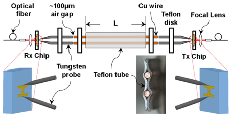
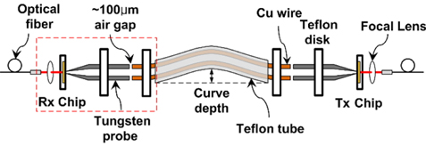
Teflon covered two-wire lines of 150 μm thickness are prepared by removing the two original stranded wires, which were separated by 1.0 mm between the wire centers, from the commercial Teflon covered two-wire lines and replacing them with the same solid 0.4 mm diameter copper (Cu) wire, which is used in the air spaced two-wire lines for reference measurement. The resulting Teflon covered two-wire lines are shown in the photo in Fig. 1, where it can be seen that small air gaps between the Cu wires and the Teflon tube were formed in the manufacturing process of the envelope. In order to fit into the Teflon disks, the Cu wires are extended 2.0 cm from both ends of the Teflon envelope as shown in Fig. 1.
Two 3.0-cm-long commercial tungsten (W) probes and the waveguide system used for this measurement are the same as used in the previous report [7]. When a THz dipole antenna is used as a short pulse emitter, the two-wire line has the advantage of allowing direct coupling of the generated THz radiation pulse to the two metal wires, similar to the case of early demonstrations of ps pulse generation on coplanar transmission lines [13]. Because the field pattern of the TEM mode of the two-wire line is very similar to the field pattern generated by the dipole antenna [14], if the ends of the two-wire line are in direct contact near the dipole antenna, the coupling efficiency will be excellent. As another example, the use of a radially-symmetric antenna on a silicon-on-sapphire (SOS) transmitter (Tx) chip was found to significantly enhance the coupling to a single metal wire [5] because the generated THz field and the single cylindrical metal wire have the same radial field pattern.
III. MEASUREMENT AND ANALYSIS OF TEFLON COVERED TWO-WIRE LINES
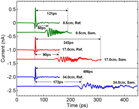
The measured THz reference pulses, transmitted through 8.5-cm-, 17.0-cm-, and 34.0-cm-long air spaced two-wire lines and the THz sample pulses transmitted through the Teflon covered two-wire lines are displayed in Fig. 2. The reference and sample pulses of the 17.0-cm- and 34.0-cm-long lines have been time shifted for comparison. The reference THz pulses show TEM mode propagation with no pulse reshaping; however, the sample pulses show significant pulse reshaping due to the strong GVD responsible for long ringing tails of the high frequency components extending to longer time duration. Such frequency dependent GVD has already been observed for a THz surface wave propagating on a metal surface coated with a dielectric film [16]. The lowest frequency components occur at the leading edge of the sample pulses and are delayed by 50 ps, 90 ps, and 172 ps for the 8.5-cm-, 17.0-cm, and 34.0-cm-long Teflon covered two-wire lines, respectively. The index of refraction for Teflon is n = 1.43 [3]. Moreover, the length L of the Teflon covered two-wire lines is given. Therefore, the respective time delays for propagation through solid plates of Teflon of the same length would be 121 ps, 243 ps, and 486 ps, as shown in Fig. 2. The consequent spatial filling factor is found according to the ratio of the respective delays to be 0.41 (50/121) for the 8.5-cm-long wires. Because much of the THz field distribution is outside of the Teflon cover, the effective index of refraction is much less than 1.43 for the lower frequencies.
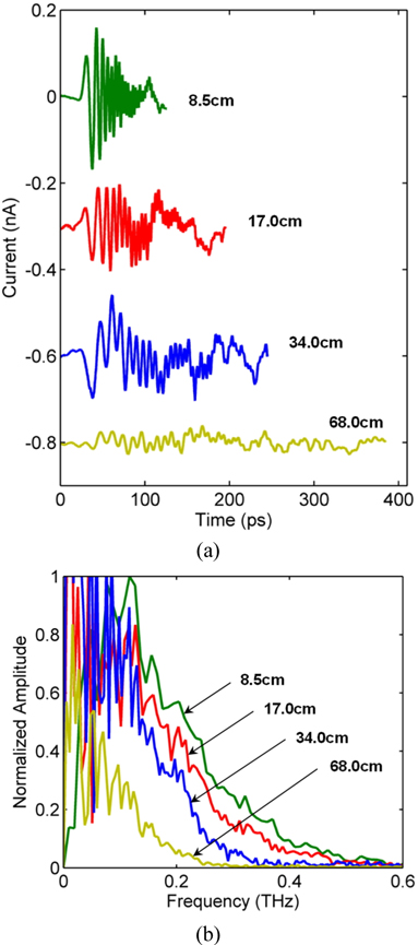
Figure 3(a) shows the measured sample pulses, which have been time shifted for clarity. Unlike the air spaced two-wire lines, high GVD is observed in the strong pulse reshaping. Figure 3(b) shows the corresponding pulse amplitude spectra. The absorption coefficient of Teflon significantly increases with increasing frequency [3], as observed by the dramatic amplitude drop in the high frequency components. As the ringing tails of the pulses become longer in the time domain with the increasing length of the Teflon covered two-wire lines (requiring a longer time delay scan), the spectra show more noise with consequent higher spectral resolution for the low frequency components. However, the amplitude of the spectra is still quite informative.
The relative amplitude absorption coefficients, calculated from the reference and sample spectra, are obtained according to
where A0(ω) and A(ω) are the amplitude spectra transmitted through the air spaced two-wire lines and the Teflon covered two-wire lines, respectively, and L is the wire length. Each amplitude absorption value shows reproducible results, indicating our measurement accuracy.
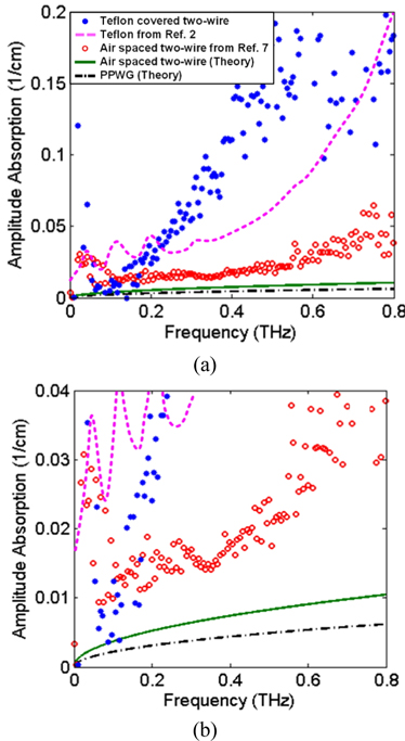
In Fig. 4, we plot the measured amplitude absorption coefficients of the Teflon covered two-wire lines (relative amplitude), bulk Teflon from Ref. 3, and the measurements of the air spaced two-wire lines. For comparison, we plot the theoretical amplitude absorption of the air spaced two-wire lines and the PPWG with 1.0 mm separation. The relative amplitude absorption of the Teflon coated two-wire lines is much larger than that of the air-spaced two-wire lines and very much larger than that of the single-wire Sommerfeld wave [3, 5].
An analytic solution for the absorption coefficients for the TEM propagation mode of the two-wire transmission line, the coaxial waveguide, and the parallel plate waveguide are given in Refs. [3] and [17]. For our air-spaced two-wire line geometry with Cu wire diameters of 0.4 mm and center to center separation of 1.0 mm, the theoretical amplitude absorption coefficient is 1.70 times larger than that for an air-spaced Cu PPWG with a plate separation of 1.0 mm. The comparative absorption strength for an air-spaced coaxial waveguide with an inner conductor diameter of 0.4 mm and an inside radius of 1.0 mm to the outer conductor is 1.86 times larger than that for the PPWG. For these three waveguides the theoretical absorption is proportional to the square root of the frequency, as shown in Fig. 4.
The measurement of the amplitude absorption for the air spaced two-wire lines is obtained by Eq. (1), for which A0(ω) and A(ω) are the amplitude spectra of the 8.5-cm long and 34.0-cm long wires, respectively; L is the length difference. Because there is no Teflon cover on the wire, the amplitude absorption is much lower than that of the Teflon covered two-wire line; however, the amplitude is approximately 2.5 times larger than the value obtained by theoretical calculation. Because the air space between the two-wire lines is not exactly 1.0 mm, the measurement absorption is larger than the theoretical absorption. Moreover, two Teflon plates are used to support the air spaced two-wire lines. These two Teflon plates cause an additional refraction loss during measurement. Although the observed general trend is that the absorption increases with the frequency, in the region from 0.1 to 0.4 THz, which contains most of the pulse energy, the absorption is reasonably constant, with a value of about 0.015/cm. This feature explains the attenuation, which occurs without reshaping the pulse propagation.
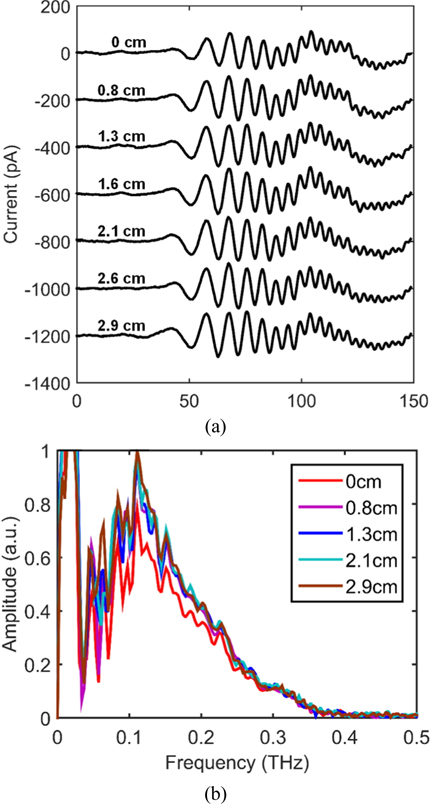
Figure 5 shows the experimental setup to measure the guiding properties as a function of the curve depth. The Rx parts shown as a dashed box in Fig. 5 move to the right to make a natural curve of the 17-cm-length Teflon covered two-wire lines. The THz signals are measured from 0 cm (straight) up to 2.9 cm curve depth, as shown in Fig. 6(a). With increasing curve depth, the peak-to-peak amplitudes of the first pulses at 0 cm and 2.9 cm curve depth are 87.8 and 144.0 pA, respectively. In contrast with the large attenuation loss of bare two-wire lines [7], the Teflon covered two-wire lines suffer no attenuation loss when the lines are curved. The corresponding spectra of the THz signals are shown in Fig. 6(b), revealing that the spectrum amplitude measured at 2.9 cm curve depth is larger than that measured at 0 cm curve depth. Because the air gaps between the Cu wires and the Teflon tube shrink when the lines are curved, the Teflon tube contacts the Cu wires closely. Therefore, the guiding property of 2.9 cm curve depth is better than that of 0 cm curve depth.
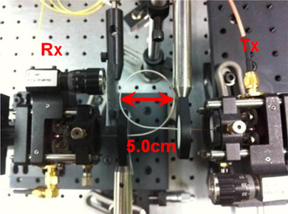
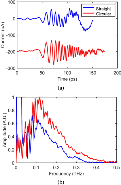
When the Teflon covered two-wire lines are curved, the lines have an excellent guiding property and no attenuation loss compared to straight lines. These properties can be exploited to detect a THz signal for circularly curved lines. The photo in Fig. 7 shows circular Teflon covered two-wire lines (360° rotated lines) that are 5-cm-diameter using the 17-cm-length lines. As expected, the THz signal of the circular lines is much larger than that of the straight lines, as shown in Fig. 8(a). Moreover, the THz signal of the circular lines shows a strong GVD response due to the shrinking of the air gaps between the Cu wires and the Teflon tube. Therefore, the ringing tails of the high frequency components extend to longer time duration. The corresponding frequency spectra, as shown in Fig. 8(b), clearly show that the amplitude difference between the straight lines and the circular lines is larger at the high frequency range compared to the lower frequency range.
In summary, we have characterized air spaced two-wire transmission lines and Teflon covered two-wire lines. Although the air spaced two-wire lines show THz TEM mode propagation with relatively low attenuation and a very small GVD, there are practical problems of how to hold the two-wire lines, how to maintain the wire separation, and how to reduce the radiation loss. However, the Teflon covered two-wire lines good maintain wire separation well and have a very good guiding property. Solving the practical problems of how to reduce the attenuation and GVD would allow application of Teflon covered two-wire lines to THz wire communication and THz wire sensors.