While valuable time and money is being wasted on disposable wet electrocardiographic (ECG) electrodes every year, they still require cleaning of the attachment sites and occasional shaving of hair from specific areas of the body, which is time consuming. Wet ECG sensors require a gel between the electrode and skin in order to offer a stable, low impedance signal path that allows for low noise measurement of the ECG signal. However, wires and gel impose discomfort and inconvenience to the patients for a 24~48 hour Holter monitoring session. They pose threats like irritation, inflammation and allergic reactions to the user/patient due to toxic properties of gel during long-term use [1]. Moreover, in situations where wet electrode gets separated from the skin or gel dries out, it is no longer effective to pick-up bioelectrical signal with the required fidelity. This situation is mostly common in the electrophysiological measurement of neonates who usually move during an ECG procedure.
Even though current wet ECG devices have impedance sensors for sensing electrode contact loss, neither is the loss data recovered nor is the operation of the system resumed [2]. These issues of wet ECG led to the invention of dry ECG sensor systems.
Dry ECG electrodes need no gel for bioelectrical signal acquisition, but they also present issues such as poor electrode-skin coupling and metal poisoning. A good conduction medium is established by dry ECG electrodes after perspiration where the sweat acts as the electrolyte at the skin-electrode interface. Dry ECG electrodes can be stiff or flexible. Stiff electrodes have the tendency to slip over the skin during slight movement causing electrode contact loss and some charging effects between electrodes and the skin. Flexible electrodes are soft and capable of lying flat on the body surface; hence have relatively higher contact area than stiff electrodes [3]. Both wet and dry ECG technologies experience huge distortion of the electrophysiological signals during high physical activity.
The idea of measuring an electrophysiological signal without direct skin contact led to the invention of contactless/noncontact ECG sensors. Actually, this technology is not new as Richardson and Lopez were the first to develop a noncontact ECG sensor system using purely capacitive electrodes, which allow for the recording of bio-potential variations through insulating materials such as clothing [4].
To record an electrophysiological signal, the capacitive sensor operates by coupling an electrode to a patient’s body through a small capacitance (about 10’s pF) [5]. Since no direct contact is necessary, capacitive sensors can be concealed in everyday objects such as clothing, stretchers [6-8], examining tables, beds [9-11], or other furniture [12-16] for long term unobtrusive monitoring of vitals or can be employed in vehicles for assisted driving [17].
However, owing to the minute nature of the electrical potential on a body surface (about 2 mV or less), noise becomes a critical issue within the frequencies of interest, and should be carefully analyzed when designing noncontact ECG sensors. Moreover, the high impedance nature of the skin has become a challenging issue in integrated circuit (IC) designs to fabricate an amplifier that can measure an electrophysiological signal through an insulating material on the skin without it getting saturated [18]. Not only is electronic noise the main contributor of artefacts in noncontact ECG sensors systems, others such as environmental electromagnetic interference commonly associated with poor common-mode rejection ratio of the ECG system, triboelectrically generated charge at the body-electrode interface, as well as modulation of the coupling capacitance under dc voltage also add a lot of artefacts that could obscure the ECG signal depending on patient grounding, degree of body motion, or the type of insulating material used at the body-electrode interface [17,19-21].
Therefore, a novel noncontact ECG electrode, designed through MEMS fabrication process, that could record a low-noise ECG signal without direct contact with the user/patient’s skin is proposed in this study.
2. CAPACITIVE PRINCIPLE OF NONCONTACT ECG ELECTRODE
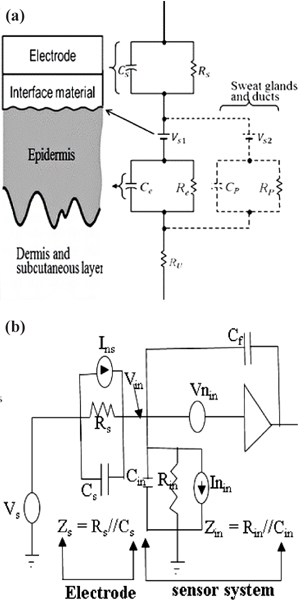
Measuring a bioelectric signal without any direct ohmic contact with the skin requires the implementation of capacitive coupling. It involves a metal electrode, an insulator and the skin coupled together to form a capacitor that enable electrophysiological measurement of bioelectric signal from the human torso with minimal discomfort [22,23].
An electrode coupled to the skin via an insulating material introduced a source impedance,
Capacitive electrodes measure bioelectric signal in the form of electrostatic charges whereby our main interest lies in the presence of charges rather than their flow. This measurement could be done in several ways i.e., measuring charges directly, measuring the electric field, or measuring the actual spatial distribution of charges, since there is no standard way to do such measurements [24]. The general circuit for a capacitive electrode electrical model is shown in Fig. 1(b). A charge that flows onto a sensing electrode with area A [m2] and impedance,
3. SENSOR DESIGN AND FABRICATION PROCESS
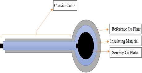
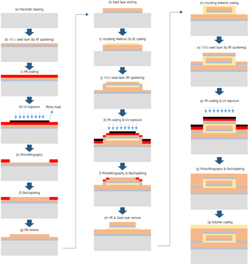
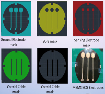
The proposed ECG electrode is a layered structure of a reference copper plate, an insulating material, and a sensing plate. The electrode lead wires are also coaxially designed to prevent cables from coupling to ground or electronic devices. Using an AutoCAD software, five different masks of the proposed electrode were designed and screen printed on light detectable films known as photomasks. The electrode was designed stepwise, in which the first step involved RF sputtering of titanium and copper seed layers on a biocompatible polyimide substrate as shown in Fig. 2. Secondly, the sample was spin-coated with a negative photoresist (THB-126N), at about 1750 revolutions per minute for 20 seconds after which it was baked at 100℃ for 10 minutes. The sample was then allowed to naturally cool at room temperature for another 10 minutes. After the cooling process, the reference copper plate was formed by applying ultraviolet (UV) light on the sample via the reference/ground electrode photomask (as shown in Fig. 4) using a mask aligner. Using a photoresist developer (DVL-2000), the photoresist of the non-photolithographical area was removed exposing the copper seed layer. The exposed area was then electroplated, giving rise to the reference/ground plate. Also, in order to fabricate sensing plate, the sample was first spin-coated again with an insulating material called SU-8. After the coating process, the sample was softly cured at 100oC for 60 minutes to evaporate the solvent and densify the film. Using mask aligner once again, the sample was exposed to a UV light source. After the photolithographical process, the sample was post expose baked at 100℃ for 30 minutes. The non-exposed area to UV light was then removed with an SU-8 developer to form the interface/insulating materials as shown in Fig. 2. The sample was sputtered again with titanium and copper film. The sensing electrode was developed following the same fabrication process as in the reference/ground copper plate design. Fig. 3 shows the entire MEMS fabrication process of the proposed ECG electrode.
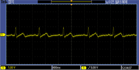
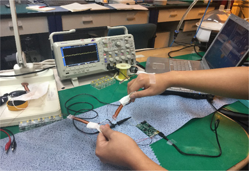
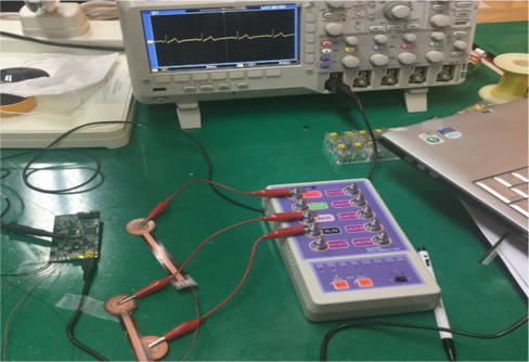
The developed electrode was tested on a 26 year old human subject with no history of cardiovascular disease. The electrodes were inserted into cotton pockets and handheld by the subject. However, the reference electrode was tightly attached to the subject’s hand using an adhesive tape, as shown in Fig. 5. To obtain a reference ECG signal simultaneously, a Techman ES-100 ECG simulator was used to generate an artificial normal ECG waveform, as shown in Fig. 6. After resting for five minutes, the subject underwent a repeated ECG measurement procedure for about six times with a resting period of 10 minutes between each session. The functionality of the developed electrodes could also be confirmed by observing the QRS complexes as well as the entire ECG waveforms in both the measured and reference signal. Both reference and the 26 year old subject’s ECG signal were synchronously recorded with TDS 2024B digital storage oscilloscope.
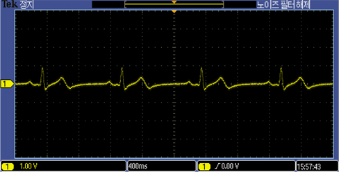
The developed electrodes recorded ECG signals from the 26 year old subject as well as the ECG simulator, as shown in Fig. 7 and 8. The ECG recordings with the MEMS designed electrodes were comparable in both simulation and experiment on the 26 year old subject.
The ECG recording of the 26 year old male using the proposed MEMS fabricated ECG electrodes was comparable to that of the ECG simulator. Prototype electrode has an area of about 2.324 cm2. It is flexible, passive, biocompatible, and capable of eliminating environmental electromagnetic interferences making it the ideal choice for recording electrophysiological signals in the form of ECG and/or EEG. The above capabilities have positioned the designed ECG electrode as a suitable choice amongst all potential candidates for taking over the market niche of biosensors in the near future. Future intentions include replacing cotton fabric with other biocompatible materials with higher dielectric constants.