The increasing use of transparent and conductive oxide (TCO) films, such as Sn-doped In2O3 (ITO), for solar cells and large flat panel displays has prompted the research and development of inexpensive TCO materials that exhibit appropriate optical transmittance and electrical resistivity for various optoelectronic applications [1].
Recently, Al-doped ZnO (AZO) and Ga-doped ZnO (GZO) thin films have been widely investigated as substitutes for ITO films due to their relatively low cost, abundance, and non-toxicity [2,3]. Among these two elements, Ga is considered to be the most promising since the covalent bonding length of GaO is more similar to ZnO compared to Al, which may induce less deformation. In addition, Ga is less reactive and more resistant to oxidation compared to Al. However, in GZO films, relatively high substrate temperatures are needed to simultaneously obtain the necessary electrical resistivity and optical transmittance [4].
Thus, a newly recommended substitute for conventional GZO and ITO films is ZnSnO3 (ZTO). One way to improve the optical and electrical properties of ZTO films is to introduce Mg and F dopants, respectively [5,6].
In this study, ZTO thin films were deposited by radio frequency (RF) magnetron sputtering on glass substrates with and without the Ag interlayer. The influence of the Ag interlayer on the structural, optical, and electrical properties of the films were investigated using X-ray diffraction (XRD), atomic force microscopy (AFM), scanning electron microscope (SEM), UV-visible spectrophotometry, and Hall Effect measurements.
ZTO/Ag/ZTO (ZAZ) trilayer films were deposited onto glass substrates (Corning 1737, 3×3 cm) by RF and DC magnetron sputtering using a ZTO target (ZnO 50 wt % and SnO2 50 wt%, 3 inches, purity 99.99%) and a Ag target (3 inches, purity 99.95%) without intentional substrate heating. Prior to deposition, the sputter chamber was evacuated to 1.2×10⁻⁴ Pa. By controlling the deposition rate, ZAZ films with 5, 10, 15, and 20 nm thick Ag interlayers were prepared. The various deposition conditions used in this study are shown in Table 1.
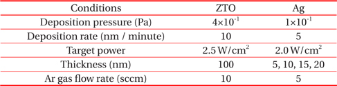
[Table 1.] Deposition conditions of ZTO and Ag thin films.

Deposition conditions of ZTO and Ag thin films.
After deposition, variations of the RMS roughness and crystallization, as a function of the Ag interlayer thickness, were investigated using an AFM (XE-100, Park System), SEM (JSM-7600F, Jeol), and high-resolution XRD (X’Pert Pro MRD, Philips at the Korea Basic Science Institute, Daegu Center), respectively.
The electrical resistivity and optical transmittance in the wavelength range between 300 nm and 800 nm were measured with Hall effect measurements (HMS-3000, Ecopia) and a UV-visible spectrophotometer (Cary 100 Cone, Varian), respectively. The bare glass substrates exhibited an optical transmittance of 92% in the visible wavelength range. The optical and electrical performance of ZAZ films were evaluated using a figure of merit (FOM) [1]. The FOM is defined as FOM = T10/Rs, where T is the mean optical transmittance in the visible wavelength region (380~780 nm) and Rs is the sheet resistance [3].
In order to evaluate the optical and electrical performance of the ZAZ films, the structure of the films must be characterized because the carrier density, mobility, and optical absorption properties of the TCO films are dependent on the grain microstructure (e.g., the grain boundary density) of the films.
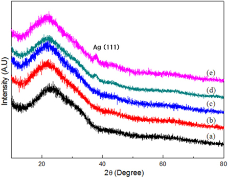
Figure 1 shows the XRD patterns of ZTO single layer and ZAZ trilayer films. As deposited ZTO films and ZAZ films with 5 nm and 10 nm thick Ag interlayers consisted of the conventional amorphous phase. These layers did not show any diffraction peaks in their XRD patterns.
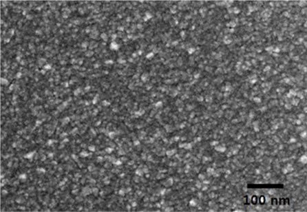
However, the ZAZ film with a 15 nm thick Ag interlayer showed a diffraction peak in the XRD pattern identified as the (111) plane of the Ag interlayer. As the Ag thickness increased in ZAZ films, the peak intensity of the Ag (111) plane also increased. The grain sizes of the Ag interlayer films were considered with the Scherrer relation and by observing the full width at half maximum (FWHM) of the Ag (111) diffraction peak from Fig. 1 [7]. The ZTO films with 15 nm and 20 nm thick Ag interlayer showed grain sizes of 10 nm and 12 nm, respectively. From their XRD patterns, the deposited Ag particles appear to form a continuous film at a thickness of 15 nm as shown in Fig. 2. However, the grain size of Ag interlayer was not confirmed by SEM image of the ZTO/Ag bilayer films in this study.
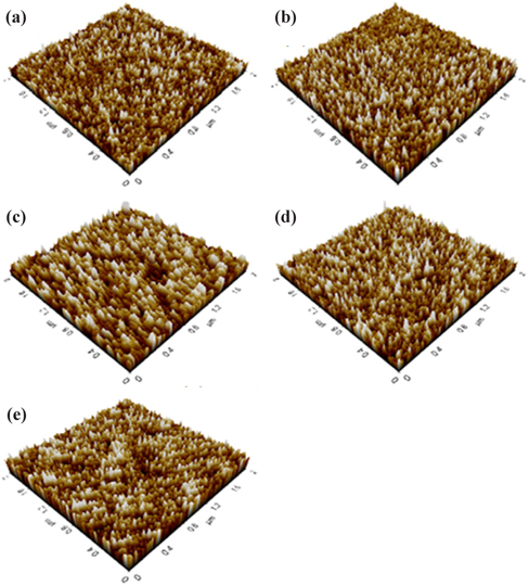
Figure 3 shows the surface images of ZTO single-layer and ZAZ trilayer films with Ag interlayer of varying thicknesses. Asdeposited ZTO films showed an RMS roughness of 0.78 nm, ZAZ films with a 5 nm thick Ag interlayer showed an RMS roughness of 1.10 nm, and ZAZ films with a 15 nm thick Ag interlayer showed a lower RMS roughness of 0.75 nm. A thicker Ag interlayer, up to 15 nm, results in a smoother surface morphology of the ZAZ films. However, the increase in the RMS roughness (1.21 nm) in ZAZ films with 20 nm thick Ag interlayer is attributed to an increased number of crystallites in the Ag interlayer, as shown in the XRD pattern in Fig. 1. J. Park previously reported a similar result where a noble Ni interlayer enhanced the surface flatness of ITO/Ni/ITO trilayer films [8].
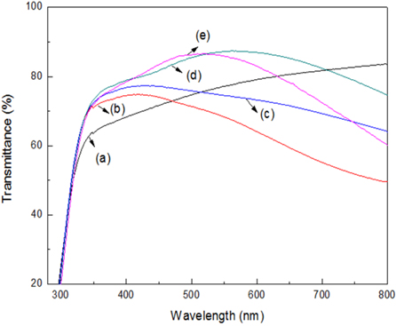
The optical transmittance measurements of ZTO single-layer and ZAZ trilayer films are presented in Fig. 4. As-deposited, 100 nm thick ZTO films had an optical transmittance of 77.2% in the visible wavelength whereas ZAZ films with a 15 nm thick Ag layer showed the highest optical transmittance of 83.2%. The optical transmittance decreased as the thickness of the Ag interlayer increased, likely because the metallic Ag interlayer absorbs visible light [9].
Table 2 shows the electrical properties of the ZTO single-layer and ZAZ trilayer films. The as-deposited ZTO films show a higher resistivity than the ZAZ trilayer films. The lower resistivity of the ZAZ trilayer films is thought to be due to the increased carrier concentration caused by the Ag interlayer. Although the ZAZ films with a 5 nm thick Ag interlayer were prepared without intentional substrate heating, a lower resistivity of 3.8×10⁻³ Ω cm was exhibited. Upon increasing the thickness of the Ag interlayer to 20 nm, the resistivity decreased to as low as 5.7×10⁻⁵ Ω cm. Although the Ag interlayer may reduce the electrical resistivity of ZTO films due to its higher carrier density, its high optical absorption is a serious drawback, simultaneously limiting the mobility by carrier scattering and the optical transmittance of ZAZ films [10].
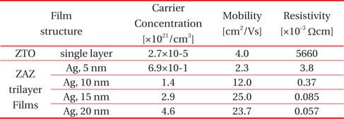
Comparison of the carrier concentration, mobility, and resistivity of ZTO single-layer and ZTO/Ag/ZTO (ZAZ) trilayer films with different thickness of Ag interlayer.
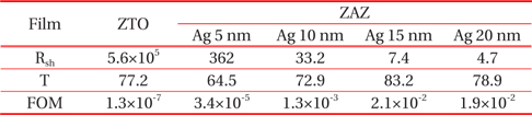
A comparison of the optical transmittance in the visible wavelength region and the sheet resistance (Rs) of the films, as a function of the Ag thickness, is presented in Table 3. In order to obtain high quality ZAZ films, the thickness of the Ag interlayer should be optimized. The ZTO single-layer films exhibited a Rs of 5.6×10⁵ W/□, and the ZAZ film with a 20 nm thick Ag interlayer showed a decreased Rs as low as 4.7 W/□.

Comparison of the sheet resistance (Rsh, Ω /? ), mean optical transmittance (T, %) in a visible wavelength region and figure of merit (FOM, Ω -1) of ZTO single-layer and ZTO/Ag/ZTO (ZAZ) trilayer films with different thickness of Ag interlayer.
Table 3 shows the FOM, which is an important index for evaluating the performance of TCO films [1]. The FOM is defined as
where T is the optical transmittance in the visible wavelength range and Rs is the sheet resistance. Although the ZAZ films with a 20 nm thick Ag interlayer have the lowest Rs, the ZAZ film with a 15 nm thick Ag interlayer shows the highest FOM (2.1×10⁻² Ω-1) due to its higher optical transmittance (83.2%) compared to the ZAZ films with a 20 nm thick Ag interlayer. Since a greater FOM value indicates enhanced optical and electrical performance in TCO films, the ZAZ film with a 15 nm thick Ag interlayer is believed to have superior in TCO applications compared to ZTO single-layer films.
Transparent conductive ZTO/Ag/ZTO (ZAZ) trilayer films with various Ag interlayer thicknesses were prepared on glass substrates using RF and DC magnetron sputtering in order to interrogate the effect of the Ag interlayer on the optical and electrical performance of transparent conductive ZAZ films.
The resistivity of the films decreased with increasing thickness of the Ag interlayer. The resistivity of the films is a result of parallel combination of the three distinct layers of ZTO, Ag, and ZTO films. Since the resistivity of Ag interlayer is much lower than outer ZTO films, the ZTO/Ag/ZTO films have lower resistivity than ZTO single-layer films.
By the calculating the FOM, conventionally used to determine the opto-electrical performance of TCO films, ZAZ films with a 15 nm thick Ag interlayer were determined to have the highest OFM (2.1×10⁻² Ω-1). These results indicate that the ZAZ film with a 15 nm thick Ag interlayer represents an alternative TCO film that can be utilized in a variety of opto-electrical devices and large flat panel displays.